

Selenium rectifiers. The name kind of sounds like Dilithium crystals, possibly related to flux capacitors.
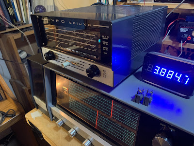
Anyway, there were two of them in the Globe Electronics V-10 VFO Deluxe that I recently bought. Obviously they had to go, so I took them out yesterday, replacing them with a 1N5408 silicon rectifier.
The new diode had a significantly lower voltage drop than the selenium rectifiers — this pushed the output voltage from the power supply up to around 200V. It is supposed to be around 185 V. So I put a 470 ohm, 5 watt resistor (found in the junkbox) in series. This brought the output voltage to 167 V. Close enough. VFO seems to be working fine.
I’m glad I did the extraction before these aging components released their nasty toxic smoke.
W3HWJ has a good article on replacing these nasty old parts, with some interesting info on their history: http://www.w3hwj.com/index_files/RBSelenium2.pdf
Backgound on the element Selenium: https://en.wikipedia.org/wiki/Selenium
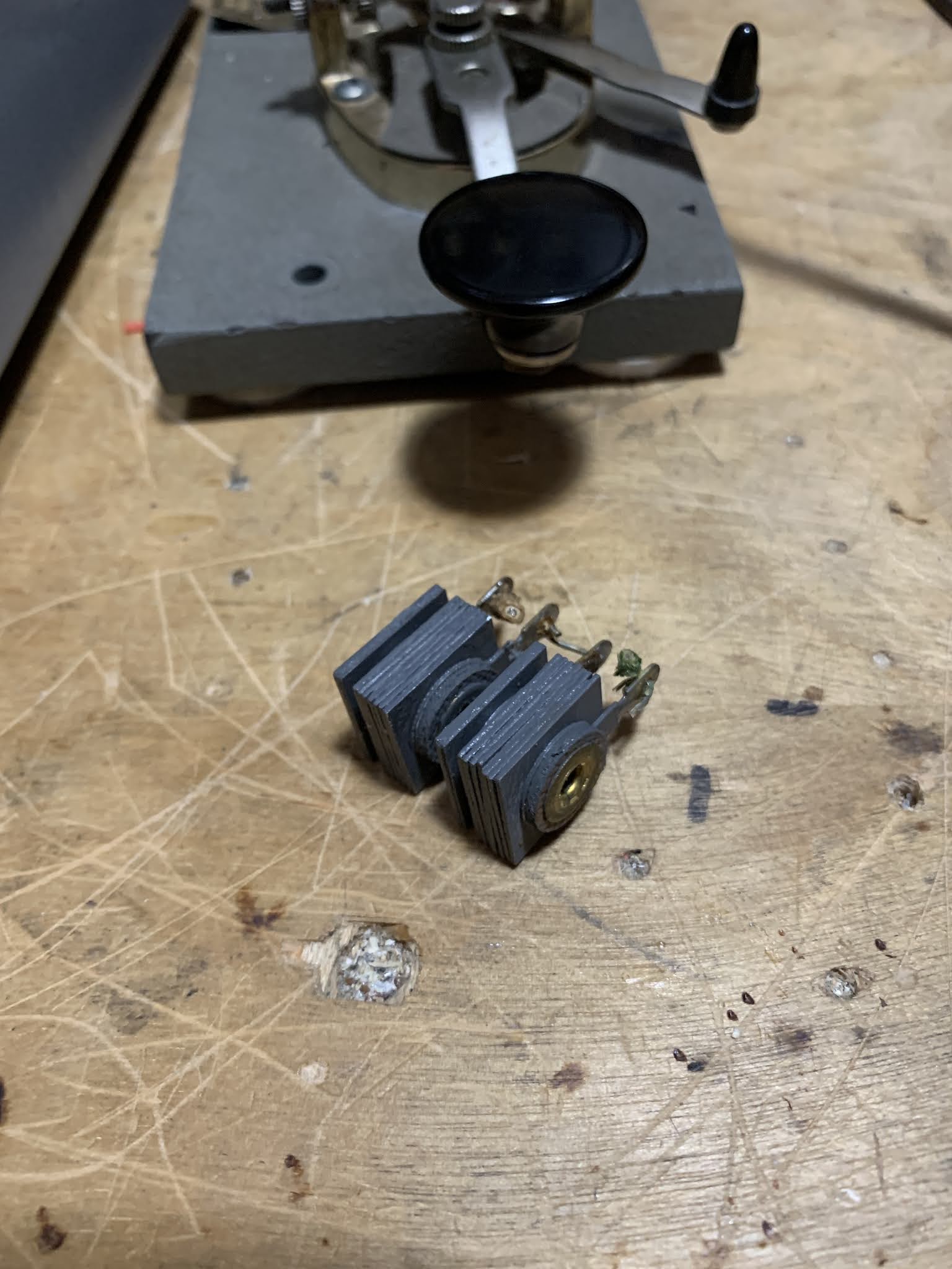
I remember a friend in my high school radio club who took a selenium rectifier apart and then demonstrated that those individual fins could be used as photocells. Destructive but more useful than our usual club activity of plugging a tube into the tube tester and making the filament go super-nova
That sounds like a great high school club. I thought about doing something like that when I read about the properties of Selenium. 73 Bill
It was a fun club but on a downward glide in 1973. The club and alumni were active on Field Day though: http://wb9kzy.com/ggg.htm We had a lot of energy those days 🙂
Why not use two diodes in series. Then you won’t get any heat build up from the dropper resistor. Nemo.
Nemo: The problem is that they Selenium rectifiers have a much larger voltage drop than the silicon diodes. So two silicon diodes would only drop about 1.2 volts total. The Selenium diodes drop about 5 volts each. That’s why you need the resistor. 73 Bill