
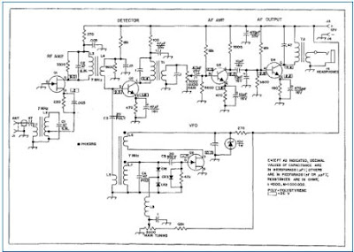
Something caught my eye this morning. Please take a look at the audio amplifier stages (Q3 and Q4) on the Herring Aid Five. Can you see an error? Above is the original schematic from the 1976 QST. Below is a 1998 update by VK1GB and KI6DS. I see the same problem in both schematics. Please let me know if you see an error.

There are missing dots on the transformer windings to say that they should be wound in the same direction. This is DC RX after all. Phasing phasing.
take it back, there ARE dots, I am blind
The first diagram is a little too blurry to fully read but the second is very clear. Anyway C14 would greatly attenuate the audio. It should be removed or made a lower value (to provide some roll-off). Also VK1GB is referred to in the blog post but VK1FB on the circuit.
That 10u C14 cap is indeed weird – that was what looked out of place to me right away as well. It is the same value as the C13 cap which brings the signal from Q3 to Q4! I would expect a much lower value if that is supposed to act as a low pass filter to take off the high frequency hiss off the signal.
Looks like the SI5351 is missing 😉
Where is the regen control. HiHi
C14 gives a reactance of abt 16 Ohm at 1kc so C14 shorts the collector of Q3, leaving no or almost no signal to Q4 unless you like sub audio.
The phasing of L6.
The value of C14 limits the audio bandwidth to about 30Hz; probably should be 0.1uf so it’s just a hiss filter.
How about putting C14 and C13 in series, and not to ground, connect negative to negative so that the effective C becomes 5 uF and is non polarised?
10 seconds flat, first (blurry) diagram, even not able to discern the value but seeing it’s an electro. Confirmed in second diag. C14 needs to be perhaps (my guess, no maths) 10nF!
C14 will short out audio to gnd