
I was thinking about spectral purity standards and the Si5351 chip. I realized that I didn’t even know what the FCC standards for “close in” noise are. The standards for spurious emissions ARE well known, but these are for harmonics and parasitic emissions relatively far from the desired signal. What about unwanted signals CLOSE to the desired signal?
My old 2002 ARRL handbook indicates that the FCC has not established firm standards for this “close in” noise. (They call it “out of band” noise, but are clearly referring to noise that is close to the desired signal but spreading out beyond the desired bandwidth. Phase noise would be in their category.)
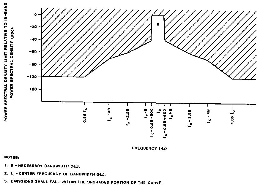
In the course of my Googling, I found the above spectral purity mask. I don’t know where it comes from, but I think it is the kind of graph that would be very useful to us as we evaluate the merits and shortcomings of various frequency synthesizers. Would our DDS or PLL rigs fit in this mask? I think an Si5351 rig WOULD. According to KE5FX’s measurements, at a mere 100 Hz from the center frequency, the Si5351 phase noise is already -90 db.
Does anyone have a similar mask showing current standards?
I still don’t understand why so many folks believe that the Si570 is a useful part for homebrew rigs, but the Si5351 is not. Look at the numbers:
Si570
Clifton Labs measuring at 30 MHz carrier. At 10kHz from carrier: -109.6 dbc/Hz
Silicon Labs web site (carrier freq not specified) At 10 kHz from carrier: -116 dbc/Hz
Si5351
KE5FX measuring at 19.99 MHz. At 10kHz from carrier: -127 dbc/Hz
Silicon Labs measuring at 156.2 MHz. At 10 kHz from carrier -112 dbc/Hz.
Can anyone out there explain the technical basis for the belief that the Si570 is a useful part while the Si5351 is not?
It is important to keep things in perspective. ALL of these noise numbers represent VERY small noise levels. Let’s keep is simple and assume a 100 watt carrier signal and a phase noise of -100 dbc/Hz. That means the phase noise per hertz would be .00000001 watts. That’s watts/hertz. How much “noise power” would that represent in a typical SSB passband? Multiply by 2500 Hz and you get 25 microwatts. That’s really low noise levels. Not enough to worry about. And as we’ve noted, we’ve happily used rigs with LC VFOs and crystal oscillators for all these years without every once measuring their phase noise.
Our book: “SolderSmoke — Global Adventures in Wireless Electronics” http://soldersmoke.com/book.htm Our coffee mugs, T-Shirts, bumper stickers: http://www.cafepress.com/SolderSmoke Our Book Store: http://astore.amazon.com/contracross-20
Hi Bill: I won’t enter the Si5135 debate, for I’ve already weighed in — however, your assertion “we never cared about PN in our LC and crystal oscillators” is not true. Although I don’t wish to generalize; I’m in contact with a ton of builders/operators and some of us – in particular those who measure things like IMD, run high performance radios, partake in group activities, or who multiply their oscillators into VHF and UHF — care about and consider sideband PN in every oscillator we build including LC and xtal oscillators. 1 of the reasons some ply LC oscillators is their potential for good phase noise performance. Of course, by themselves, LC oscillators don’t guarantee low PN. We must follow Leeson’s rules: like running a high unloaded Q in our oscillator, choosing high Q resonator components, plying low noise + low flicker noise active devices, running higher oscillator power levels, etc. One of my bench signal generators – quite similar to EMRFD Figure 7.27, was also built by an EE in the MI Lower Peninsula. At work, with access to calibrated, very low noise, Agilent gear, he measured the average PN from ~3.5 – 25 MHz @ -129 dBC/Hertz at a 10 KHz offset. This is 1 of the reasons I keep a well-designed LC signal generator on my bench. Certainly it’s also a joy to use this box as the LO in my higher performance radios. Modern commercial gear with PN performance this good costs dearly. Anyone looking for a serous signal generator should consider EMRFD Figure 7.27. Imagine what happens when we divide the signal from this box by 2 or 4 to switch a mixer and generate I – Q outputs?! Regarding crystal oscillators – again, a major reason we use them is low phase noise capability due to the high Q found in many xtals. I have some xtals where Q = 700 — and most <= 18 MHz exhibit a Q of at least 80-100K. Yes, I do measure this! Consider VHF transverters – almost exclusively you’ll see Butler or Driscoll topology xtal oscillators applied – these, when done correctly, give the lowest phase noise possible. In multipliers – double the frequency and you potentially raise the PN by 6 dB! Got to start with the lowest PN possible out of the gate – well-designed xtal oscillators dominate again. See EMRFD figure 7.32 – Wes applies a Butler at the xtal fundamental frequency to garner low phase noise and boost measurement fidelity . If you read professional literature, countless articles cover low phase noise design xtal oscillators. Many of them were written by people who are also Hams. Good Stewards About 2 blocks from here lived an amateur (now a silent key). His older commercial radio with a synthesizer PN of 116-117 dBc/Hz @ 10 kHz spacing greaved me to no end during contests --- and even on random day + nights. His Tx limited my reception of weak stations when nearby strong signals were present by raising my receiver noise floor through reciprocal mixing. Imagine what happened when he occasionally pointed his beam my way and clicked on his legal limit Drake power amplifier. A poor RF steward indeed. Best regards and thanks Todd, '7BPO http://qrp-popcorn.blogspot.ca/
I don’t think that’s how it works, you are applying that noise directly in the first mixer. Assume you have a receiver with -121dBm to -23dBm dynamic range (typical S1 to S9+50 on a true S-meter), assume you have a +7dBm VFO (usual signal used for ring mixers) that has -130dBc/Hz noise, assume you have a 2500Hz filter. -130dBc/Hz for a +7dBm level is -123dBm/Hz noise injected directly into the first mixer, wich with the typical 6dB loss in ring mixers means a -129dBm/Hz at the mixer output. This noise over a 2500Hz range means a -112dBm noise floor (you multiply noise per hertz with the square root of the bandwidth to get overall noise), wich unless you add a good preamp before the mixer means you will have a S2-S3 noise floor just from the VFO, without even connecting the antenna (remember your receiver path dynamic range starting at S1=-121dBm). Considering an AGC circuit compresses the dynamic range further, you will have a pretty bad noise in the speakers, far from a quiet receiver. You should be looking at RMS phase jitter, Si570 has 0.61ps and Si5351 has 3.5ps, the differences are significative, that’s why it’s much more expensive and people prefer it. Cheers, Razvan (YO9IRF)