
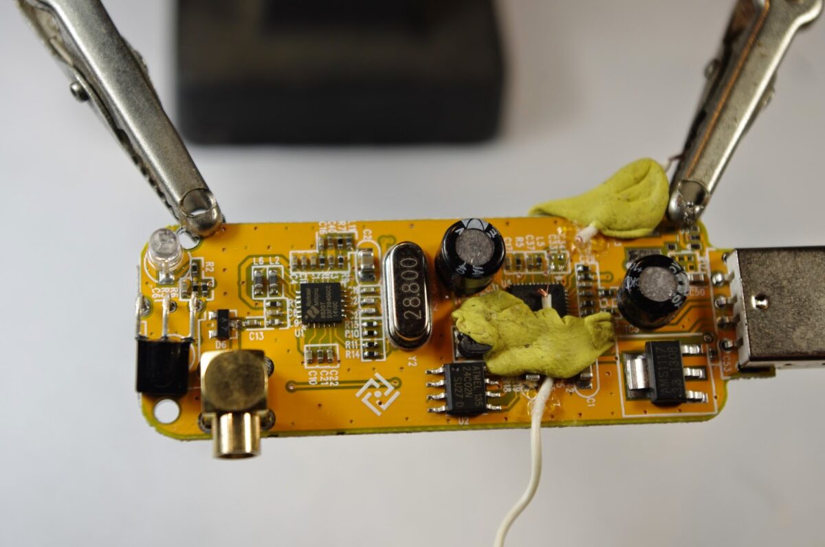
With SPRAT 162 by my side, armed with an FT37-43 trifilar wound transformer, I popped open the RTL-SDR dongle. I had hopes of being able to solder two tiny wires to the unused input pins (3 and 4) but I quickly realized that I was NOT going to be able to do that — they are far too small for me to work on. So I did what Ken Marshall G4IIB did: I took out the SMT caps going to pins 1 and 2 and soldered two small wires there. This will limit this dongle to HF only — if I want VHF/UHF I’ll just spend another $13 dollars! You can see the results in the video above.

I used the yellow stuff to hold the wires in place. It was later removed.
Tony Fishpool did a neater job. See his work here:
https://dl.dropboxusercontent.com/u/1987387/Even_more_on_using_the_RTL2832U_Dongle.pdf
Our book: “SolderSmoke — Global Adventures in Wireless Electronics” http://soldersmoke.com/book.htm Our coffee mugs, T-Shirts, bumper stickers: http://www.cafepress.com/SolderSmoke Our Book Store: http://astore.amazon.com/contracross-20
If you don’t want to wind your own transformer, you can find one in an H16105DF 10/100Mbps Ethernet decoupling transformer. Every ham has a junk box right? Pictures in this post ( http://eliasoenal.com/2012/11/07/rtl2832u-transformer-mod/ )
Bill, the secret is a big very magnifying glass and a very small soldering iron. 🙂 de Tony G4WIF
Tony: I really thought I could do it. But no. But I am glad the mod worked. Thanks for the articles in SPRAT. Bill
There is even more dongle madness in the next Sprat 🙂
Fascinating Michael. I hooked out a gigabit ethernet card from the office junkbox and the filter is a midcom 7093-37. The datasheet is online and it is similar to the filter referenced in your article. That lead me to an article with more info: http://yu3ma.net/wp/?p=370 There is some advice about adding a capacitor to the USB 5v and clamping filters around the USB cable to reduce noise. I get quite a bit from my monitor. I’m wondering now whether the HF performance of my dongle is not as good as it could be because I didn’t remove those capacitors in order to retain VHF?
Tapping an IF should be your next next mission Bill. Welcome to RF TV 🙂