
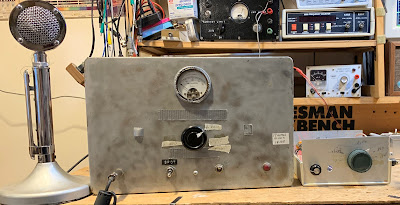
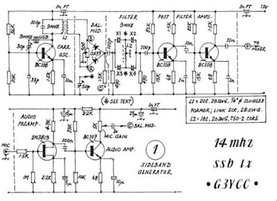
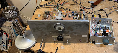
I built the transmitter almost 20 years ago. It is in the larger box, which originally housed a Heathkit DX-40. There is a lot of soul in that old machine. Details on this construction project are here: https://soldersmoke.blogspot.com/2021/12/junk-box-sideband-from-azores-2004-qst.html (The smaller box is a Barebones Superhet receiver set up for 17 meters.)
In the 2004 QST article I discuss a problem I had with “spotting” or “netting.” This is something of a lost art, something that you had to do back in the pre-transceiver days, when running a separate transmitter and receiver. This was how you got the transmitter on the receiver’s frequency. Essentially you would turn on the carrier oscillator and the VFO and let a little signal get out, enough to allow you to tune the VFO until you heard zero beat on the receiver. My problem was that around one particular frequency, I would hear several zero-beats. This made netting the receiver and the transmitter hard to do.
Important note: This is really just a problem with the “netting” or “spotting” procedure — the problematic spur does not show up in any significant way in the output of the transmitter. I can’t see it on my TinySA. But it is strong enough to be heard in the unmuted receiver sitting right next to the transmitter. And that creates the netting problem.
In the QST article, I said that I noticed that the problem seemed to be centered around 18.116 MHz. As I approached this frequency, the tones — desired and unwanted — seemed to converge. That was an important clue. In the article I said I thought that I could eliminate the problem with just one trimmer cap to ground in the carrier oscillator, but looking back I don’t think that this really fixed the problem.
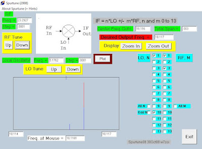
I recently took a fresh look at it. Exactly which frequencies were causing the unwanted signals that appeared in my receiver?
I used an Excel Spread sheet to find the culprits.

A quick and dirty fix that might work – or at least prove you’re on the right track – could be just a series tuned trap on the offending harmonic across the carrier osc output. A trimmer with a max capacitance of 30 or 50 pF and maybe 5 to 10 turns of wire wrapped around a pen should be about right.
Quickest thoughts: Redesign LO [1] Choose a LO that produces less overtones: e.g. Colpitts where 1 half of the crystal gets AC grounded via a cap or a series L – C [2] After LO, lightly couple an untuned buffer amp to drive bal. modulator. e.g. Common base with untuned (broadband)collector; or if using tuned collector tank, shunt a low K resistor to drop the tank Q. and/or [3] low pass filtration of LO and/or VFO
In a NE602 (which seems to be the mixer used in your transmitter) the level of spurs at the output increases dramatically if you do not pay enough attention to the level of IF/VFO signals. I would try using a looser coupling (gimmick cap?) to the VFO and see what happens to the output spectrum of the mixer best 73/GL Henk/PA0EME
I had the pleasure of a contact via this rig in 2002. I was very suprised to receive my green stamp reurned with the inscription “this dollar bill has travelled from ZL to the Azores and return” vry 73 Bill best DX Peter
FB Peter! Here is the log entry for April 13, 2002: 13 April 2002 0556 17S HP2CQB 59 Jose 0626 17S WE4H 57 Bradenton Fla. Goerge 0807 17S ZL1PWD 57 Peter N. Island 0819 17S SM0OWX 57 Chris Says SSB Rig Sounds Good 1132 17S VE3OWV 55 Nick 30 mil W of Ottawa HB Amp, also runs HB 6 meter XCVR and DX-100 Also working on HW-100 21.425 AM 20 CU2AAL Ernesto told me that signal is fine after I told him that he should drop…?
My cleanest homebrew receiver has high side VFO, as is yours. A buffered and low pass filtered BFO — entirely enclosed and with bypassed DC supply line, inside a rail modellers brass box. The VFO is not low pass filtered but well away from the rest of the receiver. (This is NOT one of my compact portable rigs!). The other ideas also sound good. I like reducing the LO level into the NE602, you don’t need much pF there! Best of experimenter’s luck to you. Paul VK3HN.