Don’t miss the new posts on the BITX HACKS blog. There are some great ideas from Don ND6T and some wonderful tribal knowledge from Pete N6QW.
http://bitxhacks.blogspot.com/

SolderSmoke Daily News — Ham Radio Blog
Serving the worldwide community of radio-electronic homebrewers. Providing blog support to the SolderSmoke podcast: http://soldersmoke.com
Don’t miss the new posts on the BITX HACKS blog. There are some great ideas from Don ND6T and some wonderful tribal knowledge from Pete N6QW.
http://bitxhacks.blogspot.com/
Many thanks for your respective responses to my plea for help in setting up SI5351 derived BFO to my BITX40 board. You were both on the money.
These BITX40 boards that Ash Farhan has developed and released to the world wide community of Radio Amateurs are worth every penny. Because they are so hackable (not just the circuitry but now the Raduino code also) it means that you can tailor it to your specific specification and in the process you are likely to learn new stuff and make new friends. I describe my BITX40 incarnation and experiences below:
Upon first firing up the BITX I was getting quite a lot of mains hum from my PSU’s (I thought that at least one of these PSU’s was a quality item) but obviously not up to the job. I constructed a simple one transistor capacitor multiplier (this converted a humble 1000uF cap into a 1F cap) and the noise magically disappeared. By coincidence I note that Bill discussed this technique in a recent pod cast. Another advantage of this technique was that I got a 2V drop across the transistor so by running this on 13.8V I get 12V out so I run the PA section on un-smoothed 13.8V (this gives me 12 watts of RF out) and run the receiver section on the smoothed 12V output from the multiplier, happy days.
My thoughts were to turn my BITX into a multi band (several bands rather than all bands) rig and I figured that using high side mixing (running the VFO at 19Mhz (12Mhz + 7 Mhz) rather than the existing low side mixing (12Mhz – 7Mhz=5Mhz VFO)) would be a better option. For example running it on 17M would mean using high side VFO anyway. I also wanted the ability to be able to switch sidebands especially on the lower frequencies so that I could use the rig for Digital modes in my case this was to be achieved by coding the Arduino to run a BFO on one of the SI5351’s clk ports.
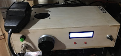
I bought my BITX prior to the release of the Raduino so I had already commenced (with the aid of a new found radio friend and RF mentor) coding an Arduino VFO/BFO using a UNO and SI5351. Like I said at the beginning once you let folk know that you are starting on a new and interesting project you start to engage the more practical members of the ham community and they just want to get involved and help. Yet another good reason to buy a BITX . We used code originally developed by Jason Mildrum NT7S and Przemek Sadowski SQ9NJE and tailored it to suit the BITX40 and our requirements. This include high side VFO with frequency step adjustment and a BFO with long push BFO changeover. This meant that my BITX front panel should stay very minimalistic 2 knobs.
Getting the VFO to work was simple as the DDS socket was used and to better accommodate the high side VFO I modified the board by tombstoning caps C91 & C92.
Getting the BFO to work proved to be more problematic I was troubled with hiss and other noise. Words of wisdom from Pete Juliano when asked if I was doing something wrong were: ” No –it is just that we tend to think our projects are like Lego type building blocks where everything mates and snaps together. Sometimes more is required”. True Pete and that gives us the opportunity to learn new stuff!
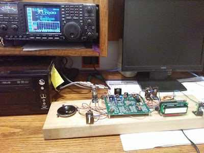
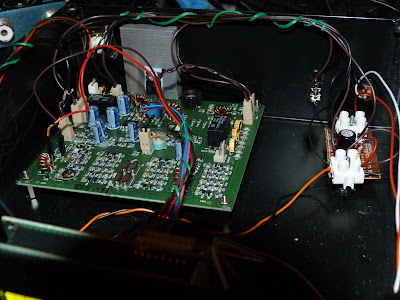
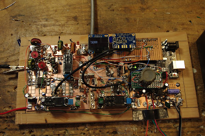
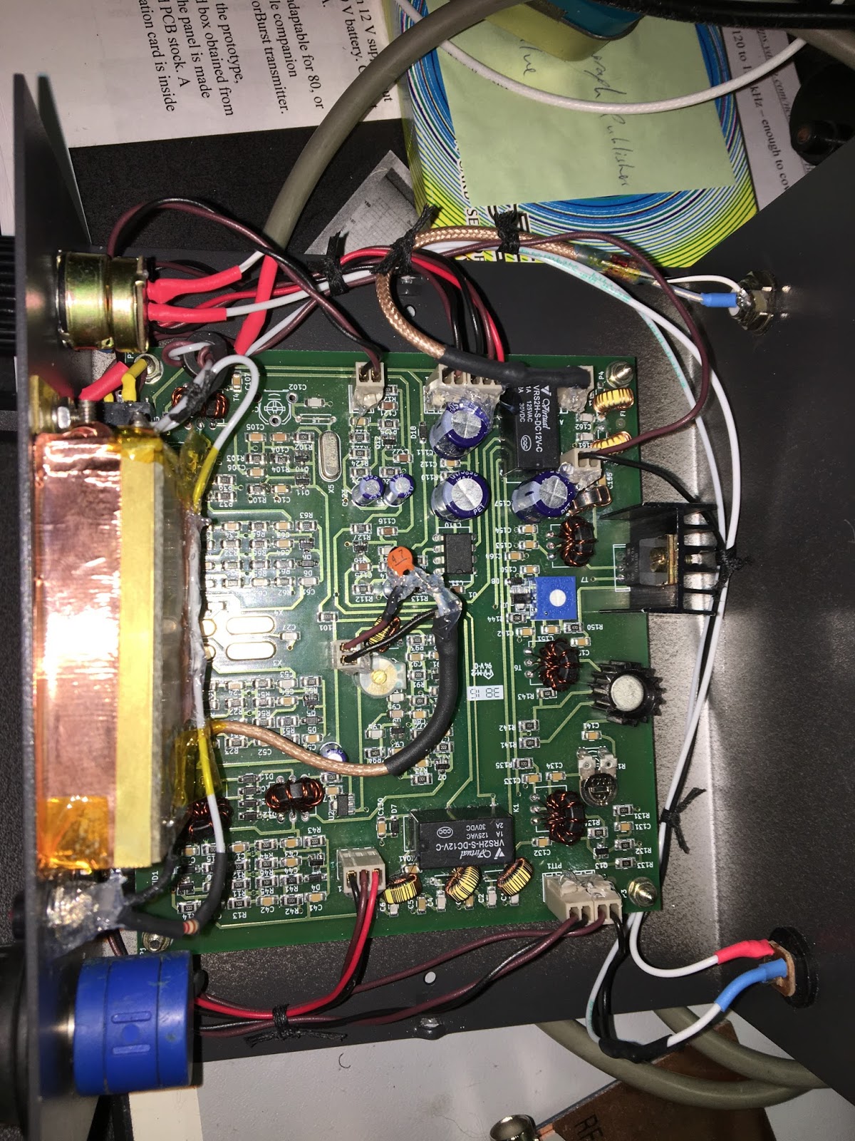
To cut a long story short I found that the best place to connect the BFO was on the modulation transformer T4 thus bypassing the BITX BFO stage altogether. I was also getting hash noise believed to be emanating from the Uno. At this stage my after market Raduino arrived from India. I fired this up and noticed that I was not getting any hash noise from it. This pointed us to a coding problem and the LCD refresh was altered on our code and the problem disappeared. Below a picture of the module showing the BFO connections to T4 and the large heat-sink with the IRF510 insulated from it. Also shown is the capacitor multiplier and a glimpse of the Raduino in the foreground. Not the most elegant box but this is likely to change pending further refinements. It’s still work in progress and this box gives me plenty of room.
The Raduino is a fantastic piece of kit for the money extremely neat and well thought out. The coding is comprehensive and innovative and works well. However, from an aesthetic and ergonomic point of view there were a few things that I personally did not like in terms of how it operates and performs. I could not get away with the potentiometer tuning, you can tune 50Khz of the band and then when you near the pot edge it increments/decrements and you can re-tune. I found this clunky to use and in addition the Raduino would hunt causing the last digit to increment then decrement causing an annoying warble on audio. In my opinion a Rotary Encoder would be better solution. On the plus side, although not mentioned on the Hfsigs web site the Raduino code does come with other functions such as changing sidebands by temporary high siding the mixer, a RIT, VFO B and CW tone. If you download and read the Raduino code from Github you will see this extra functionality which I believe you can make use of via extra switches (not supplied). The current Raduino code does not have any external BFO options as said it relies on the crystal BFO and temporally high siding the VFO to change from LSB to USB on 7Mhz.
The Raduino module itself is just too good and neat not to use. As I did not have the where for all to fully understand and amend Ash’s code I decided to use the Raduino but to load it with the code that we have developed for he Uno and Addafruit SI5351 board. This would give me near conventional tuning via a rotary encoder, adjustable step sizes via quick push of the encoder switch and USB/ LSB switching via long push of the encoder switch by virtue of the SI5351 generating the BFO frequency. I have retained a copy of Ash’s Raduino code just in case I wish to revert to it. I put a new header on the Raduino P3 connector so that I could connect a rotary encoder and use the 2nd clock output and then changed our code to run on a Nano. I had to add a correction factor in the code to cater for calibration differences in the SI5351’s (in my case 1.21Khz).
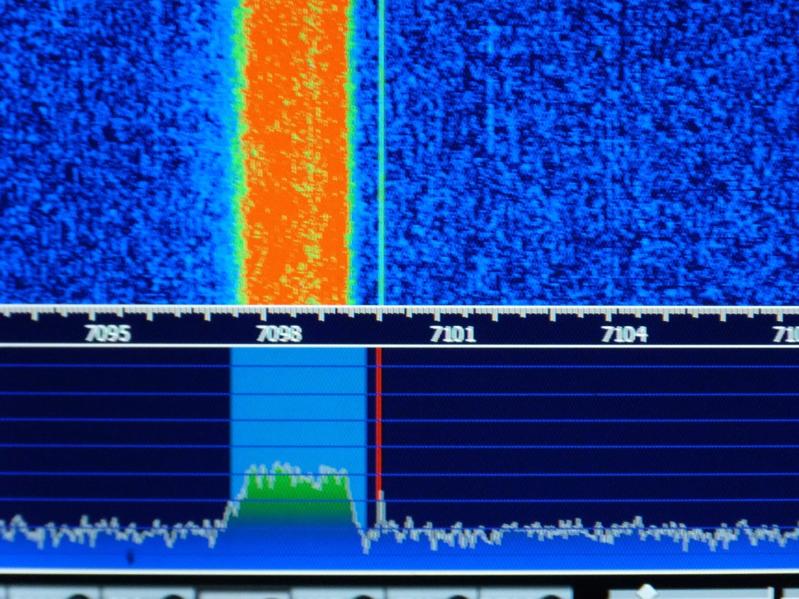
As previously indicated I had a little trouble arriving at the correct BFO frequencies I found that 119940 and 119970 gave me LSB and USB respectively for my high side VFO (19Mhz) if you use low side VFO (5Mhz) then these would be reversed. We further refined these frequencies by injecting white noise into the mic amp and looked at each transmitted sideband on my RTL-SDR dongle via HDSDR (a useful piece of test equipment). By adjusting the carrier trimmer to show the carrier in the extended HDSDR spectrum display we could see how much to move the BFO frequency to best occupy the crystal filter pass band, see image below. This frequency adjustment being achieved by a coding change. The frequencies I consolidated on to cater for my particular crystal filter are 119941 LSB and 119969 USB. We then nulled the carrier back out. My audio is now as smooth as a maiden’s inner thigh, trust me the image will follow!
In the mean time folk should just get a BITX40, hack it to bits and share with us their customised versions.

Rob VK4FFAB wrote a really nice series on how to get started with the LTSPICE circuit simulator. I’m sure these articles will also have a lot to offer for those of us who’ve been using LTSPICE for a while now. Thanks Rob!
Rob’s articles can be found here:
http://vk4ffab.info/lt-spice-for-radio-amateurs/
This is going against everything I believe in, but I admit it — I want one of these.


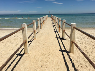
Last weekend Homebrew Hero Peter Parker VK3YE hosted another of his amazing twice-yearly QRP events. It was at a park near the iconic Chelsea Pier in Melbourne. Peter Marks VK2TPM sent a very nice write-up with pictures:
http://blog.marxy.org/2017/02/qrp-by-bay.html
And a nice audio report:
http://s3.marxy.org.s3.amazonaws.com/audio/QRP_By_the_Bay_2017.wav
Peter Marks reports that most of the on-the-air activity was on the 120 foot ham band (40 meters for you modernists). Many BITX40’s were on display.

First let me say that I have been an avid follower of the SS blog and podcasts since the days of your podcasts involving Mike KL7R.
Like many others I was tempted to purchase the $49 surface mount module from HF Signals. As a keen home brewer I felt guilty about employing a prebuilt board but excused my decision on the grounds that I would build a DDS and other accessories myself.
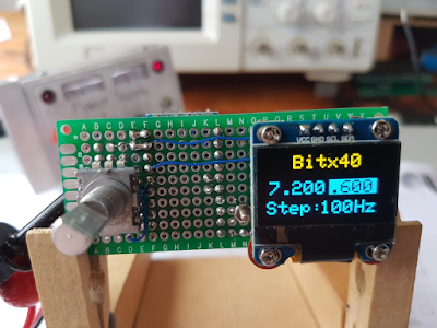
In addition to follow the SS blog I also check Pete’s blog regularly and was excited by his OLED VFO for the Bitx40.
I constructed it on a small double sided matrix board with plated through holes. A bit of noodling led to the layout shown in the photos. There is only one board with components mounted on both sides. The board came to life on the first power up but the text spilled off the bottom of the display.
I assumed that the sketch that I had downloaded from Pete’s blog was for a different OLED module. I knew that he had also used a yellow/blue OLED, the same as mine, previously so emailed him requesting a sketch for this OLED.
I was taken aback when he informed me that the sketch I had was the same for both the dual colour OLED and the black and white one too. Pete suggested that I swot up on the use of OLEDs generally and that perhaps I should first experiment with the text size to begin with. He also offered some advice about the mapping of the screen.
I soon discovered that the text size was not the cause of my grief and that I needed to look elsewhere.
I first tried running the ssd1306_128x64_I2c sketch from the sample sketch folder and was rewarded with the message “Height incorrect, please fix Adafruit _SSD1306.h”. A search of the Internet revealed that I needed to edit the .h file and find “#define SSD1306_128_64” which was commented out and uncomment it and make sure that the other two options, _32 and _16, were commented out.
My next problem was how to edit the specified .h file. I tried notepad but the text all ran together. Another internet search revealed that Notepad++ was a suitable choice and it did indeed cut the mustard.
A reload of the sketch completely restored the display to full functionality.
All this may be obvious to many but it was all new to me and if I had not been prompted by Pete l would not have had learnt so much and would not have had the same sense of achievement when it all came together.
Many thanks to you and Pete for providing a focus for my hobby.
73’s
Hugh ZL1UEM
I started playing with the RTL SDR dongles again. I wanted to use them to confirm that my BITX signal is NOT 9 kc wide (it is not). I also wanted to try to confirm the aircraft band frequencies in use in this area.
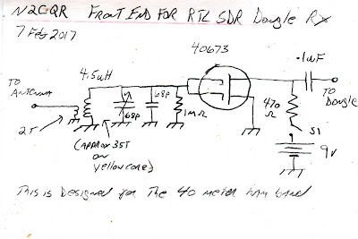
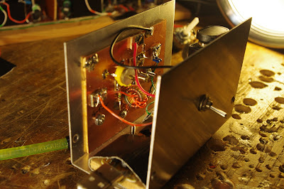
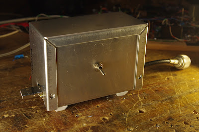
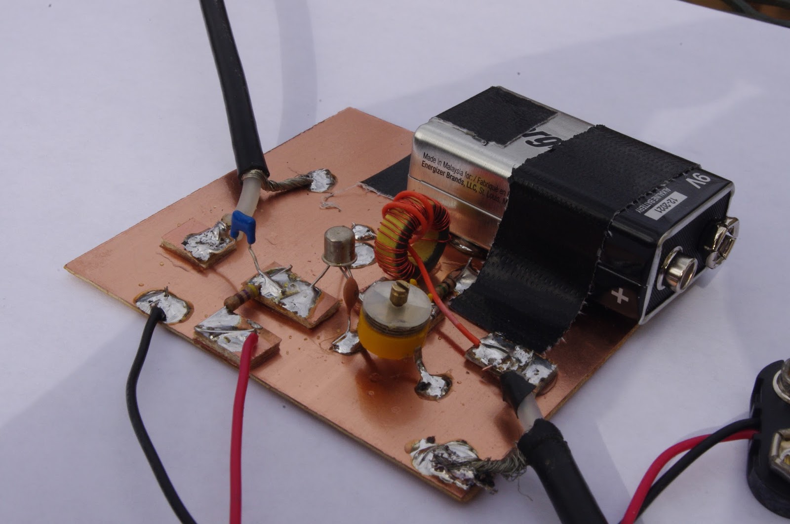
So I got the HDSDR software running and plugged in the dongle that I had modified for HF use. It worked great, but I could see (literally SEE) that it needed some bandpass filtering and perhaps a bit of RF gain. So today I threw together this device. Dual gate MOSFET (gates tied together) with an LC filter on the gate. Power from Malaysia via the 9V battery.
It works great. It was fun to add a bit of homebrew to an otherwise soul-less commercial receiver. But beware: that waterfall is addictive, even for a hardcore Hardware Defined Radio guy like me.
So cool. You can just feel the enthusiasm. Congratulations Brad!
Bill and Pete:


W8LM wrote (on the BITX20 group):
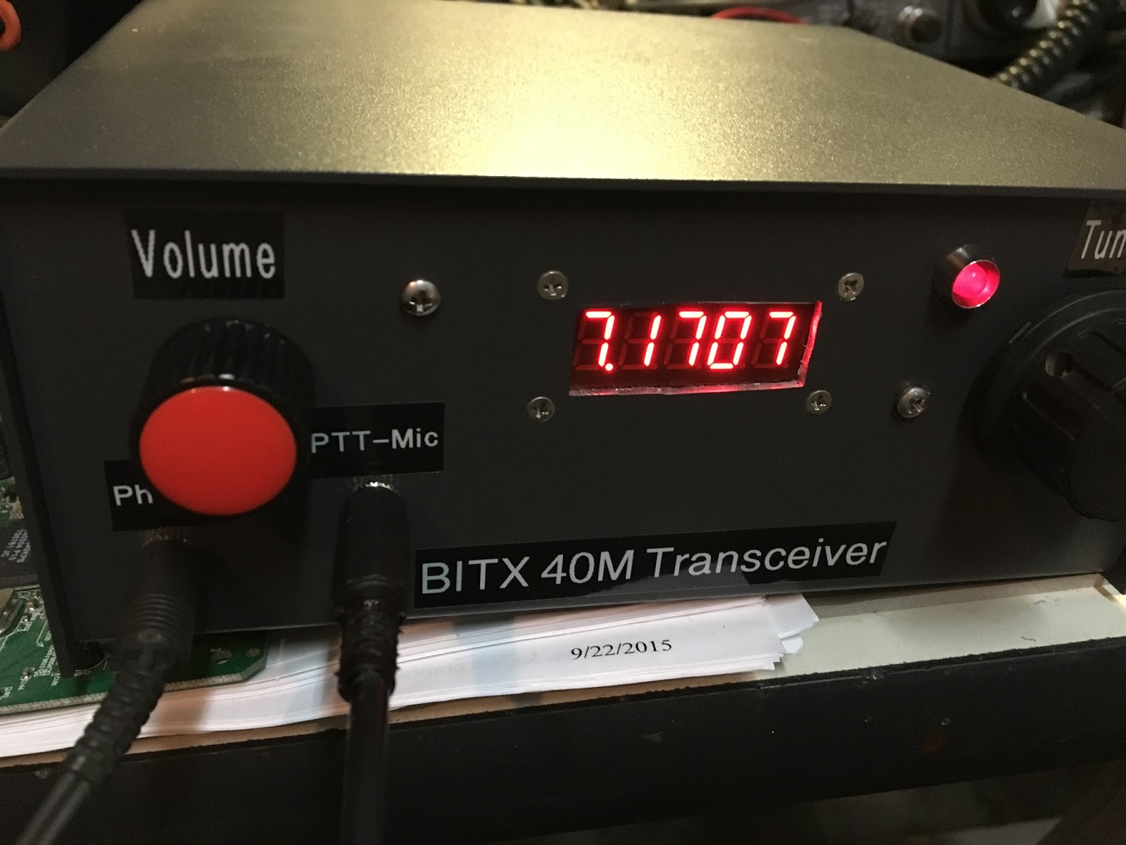
Guys- Here are pix’s of my BITX40 fired up today in Receive for testing. #1 I have the tuning clicks- so I will be debugging that. #2 shown in the pictures is my test of calibration which was not necessary. I used a T and put my ICOM 756proII and the BITX40 on the same antenna (a Windom flat top at 33Ft) The display of both read 7.1700 pretty much the center of the band and I was copying 4’s,8’s and 2’s at 23:30zulu) By moving volume controls up and down I could listen to both rigs same frequency, audio comparison acceptable. An AGC circuit is in order. The mylar-plastic cone of the surplus speaker lacks fidelity. Unfortunately the 16×2 display did photograph well. It’s a start– de W8LM

Martin A65DC sent us this wonderful report on his efforts in the UAE. His e-mail nicely conveys his enthusiasm. I was especially pleased to see that wooden enclosures are catching on (another fellow on the BITX20 group is using a cigar humidor). Thanks Martin! Please keep us posted on your UAE homebrew adventures.
Hi Bill and Pete,


 |
Our friend and BITX builder Colin M1BUU has opened up a new area for ham radio masochism: EXTREME MOUNTAIN-TOP RIG BUILDING. That’s right my friends. You read that right. Colin has taken the solder smoke to new heights. Soon, these guys will be pouring scorn on those of us using “shack built” rigs. Congratulations Colin! Well done!
Colin’s write up from http://reflector.sota.org.uk/t/colin-m1buu-mountain-goat/14559 :
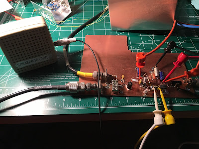
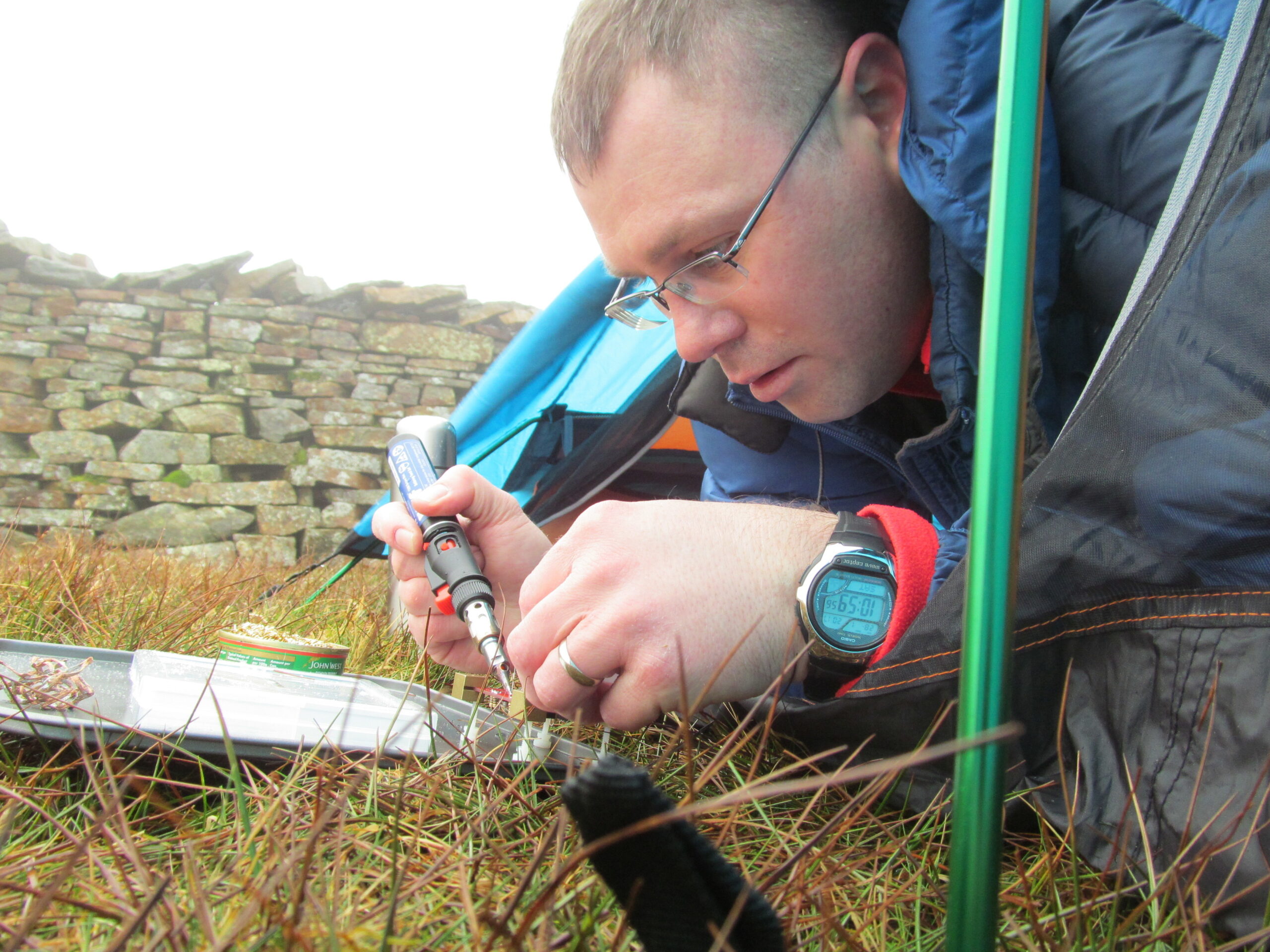
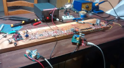
Being a prolific builder of radio kits, I thought I would do my own twist on Extreme Ironing – Extreme Solder Ironing!
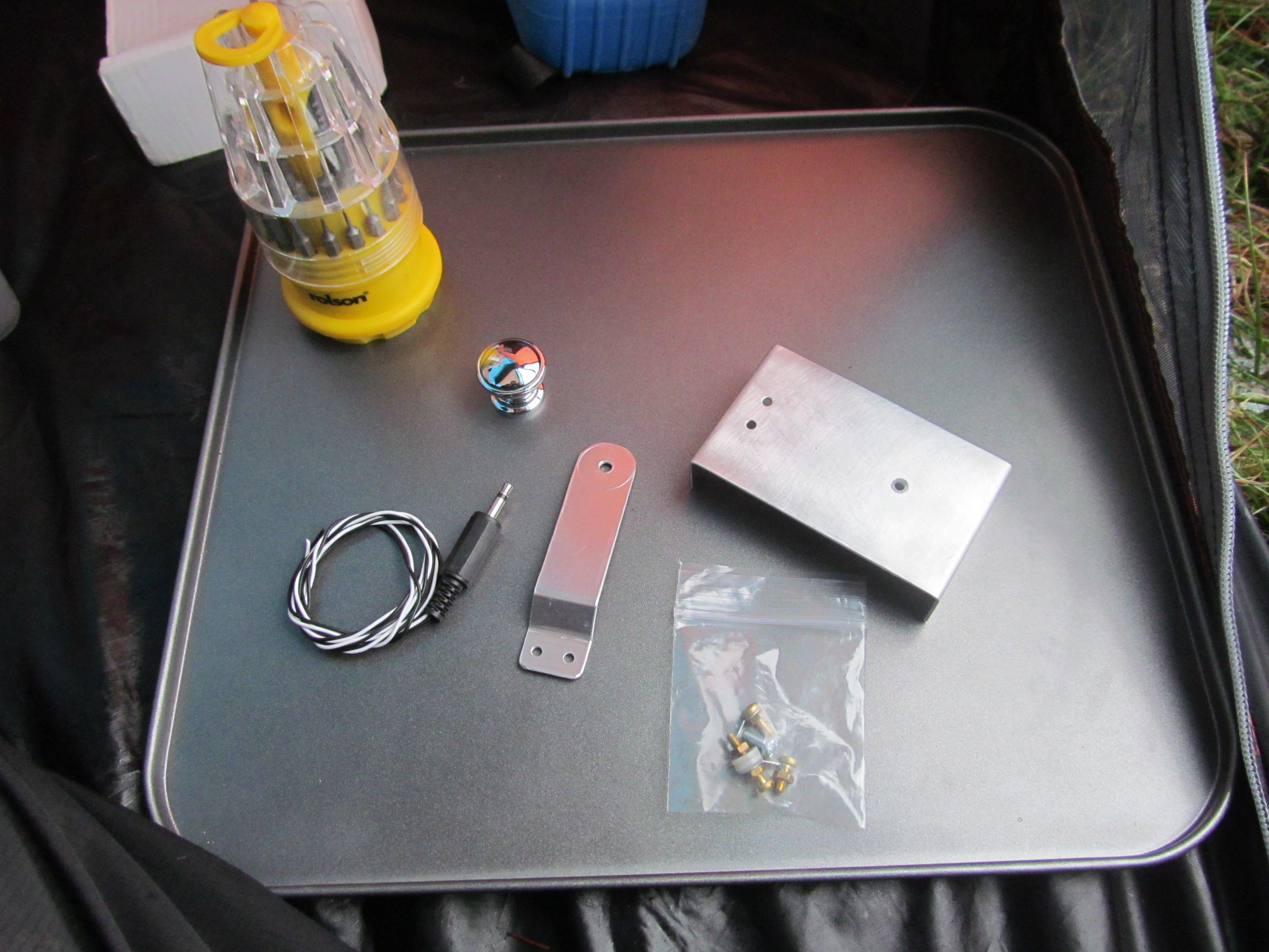
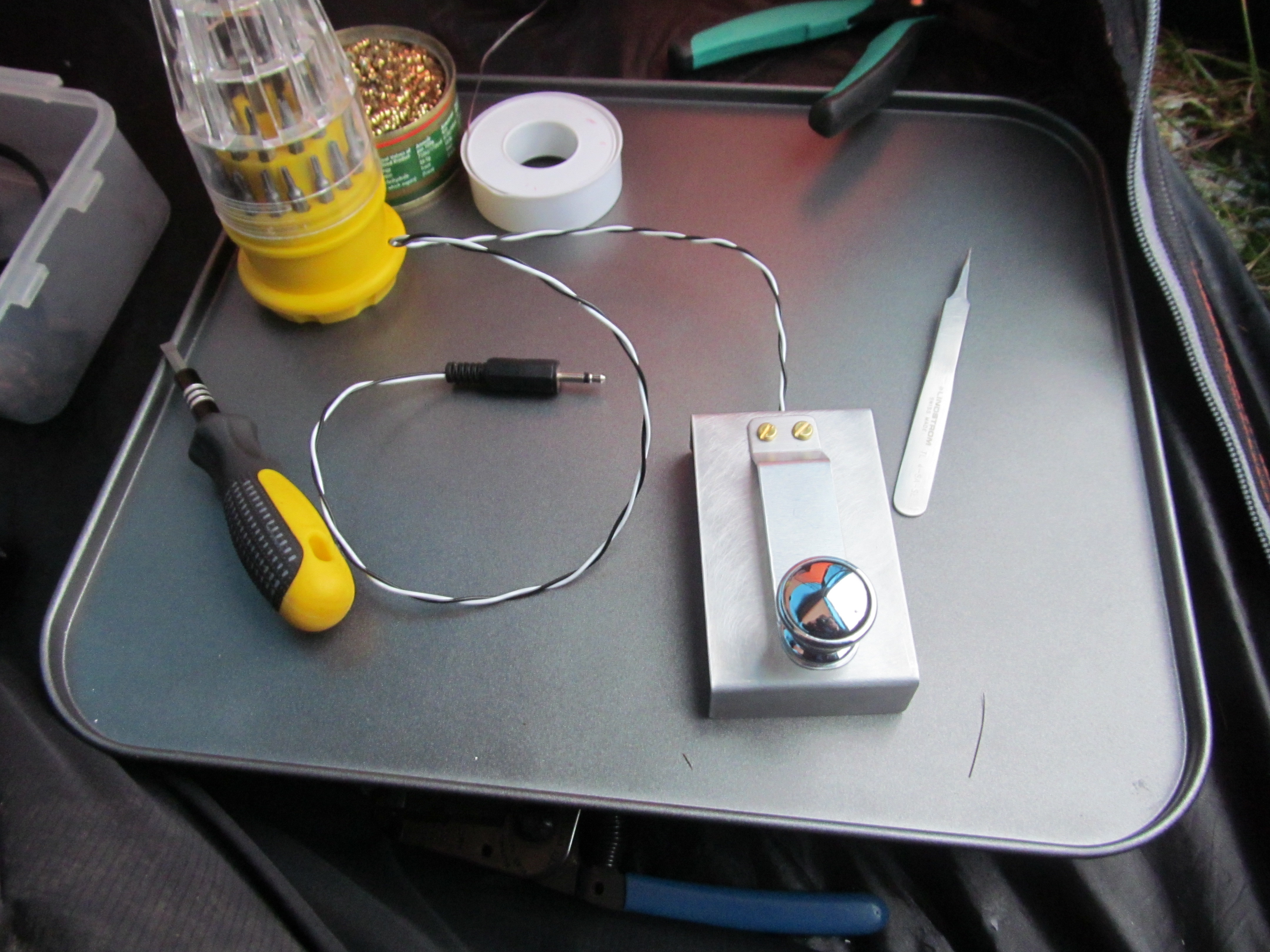
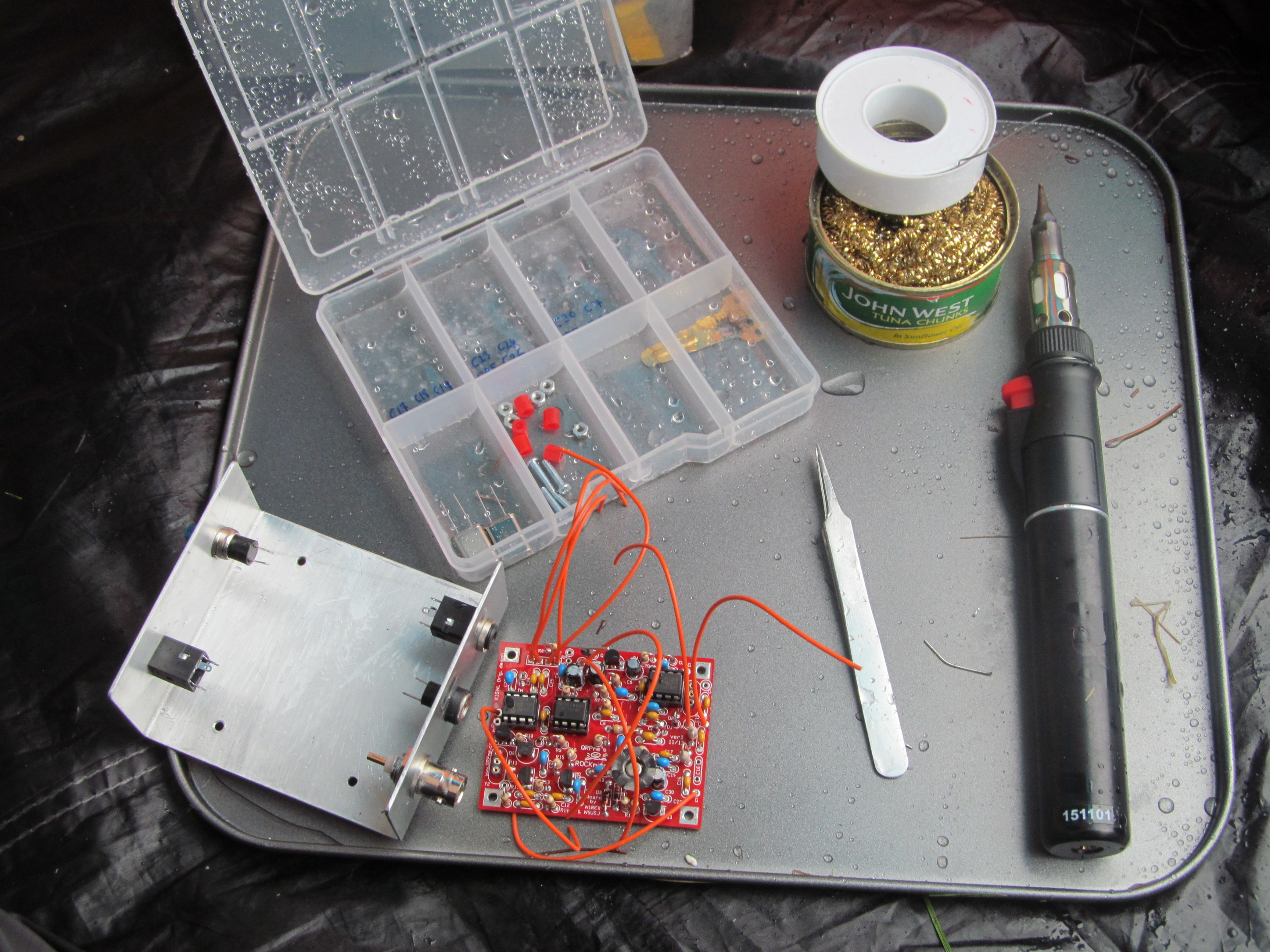
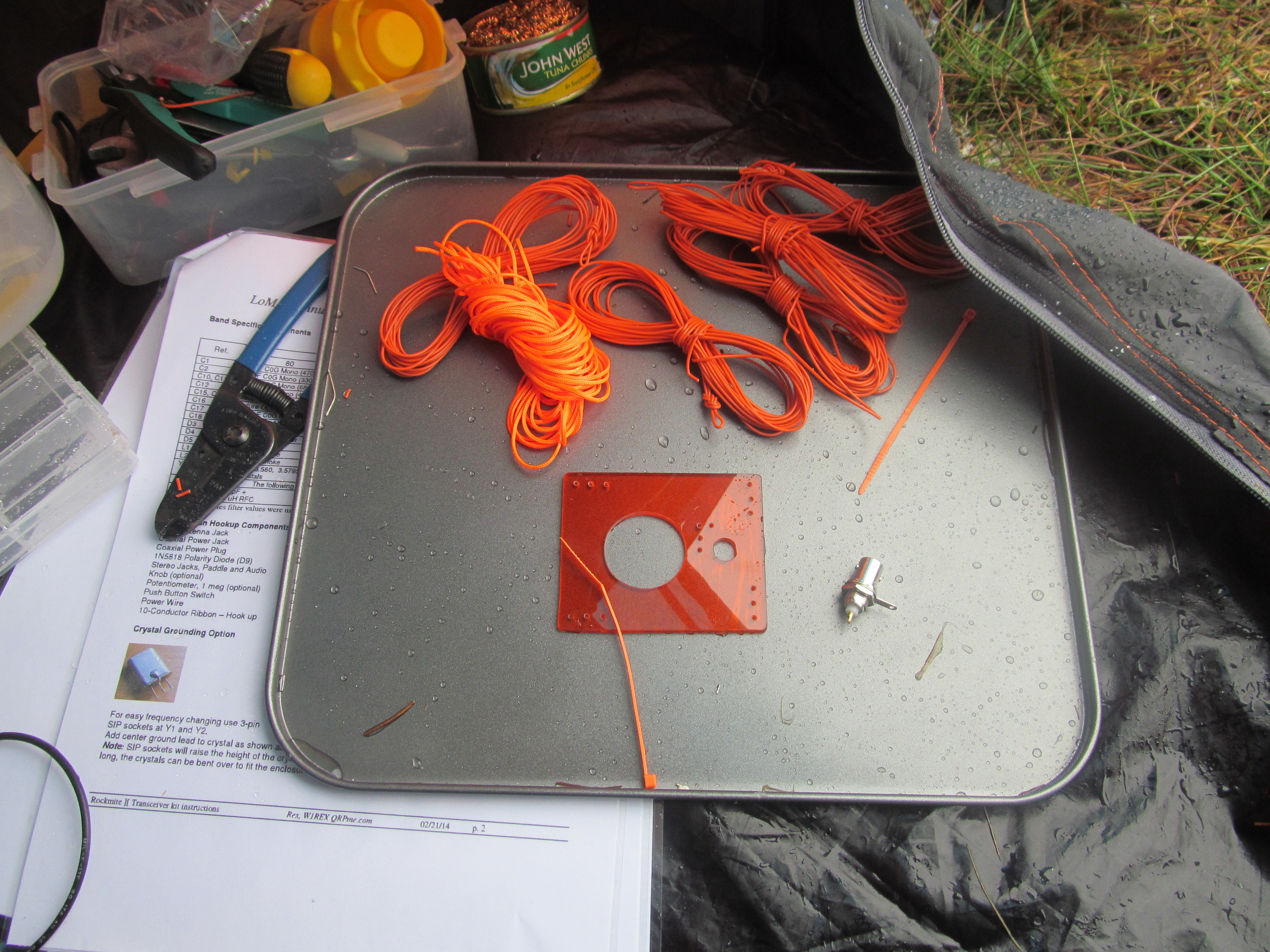
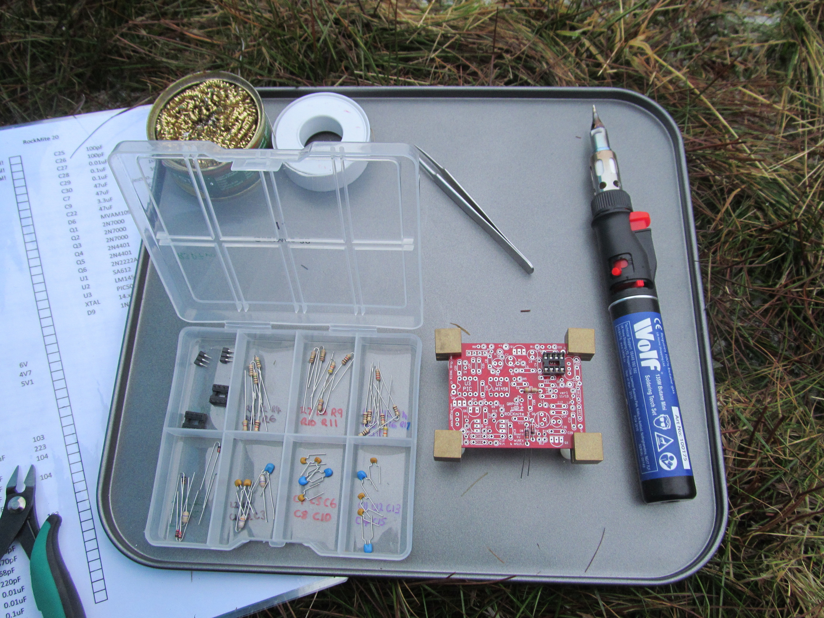
Today was the day. I took a RockMite kit, a home made key kit and a home made vertical antenna kit up to the summit of Whernside G/NP-004. I assembled the kits using a gas powered soldering iron. Thankfully I took my little tent with me, the weather wasn’t exactly tropical.
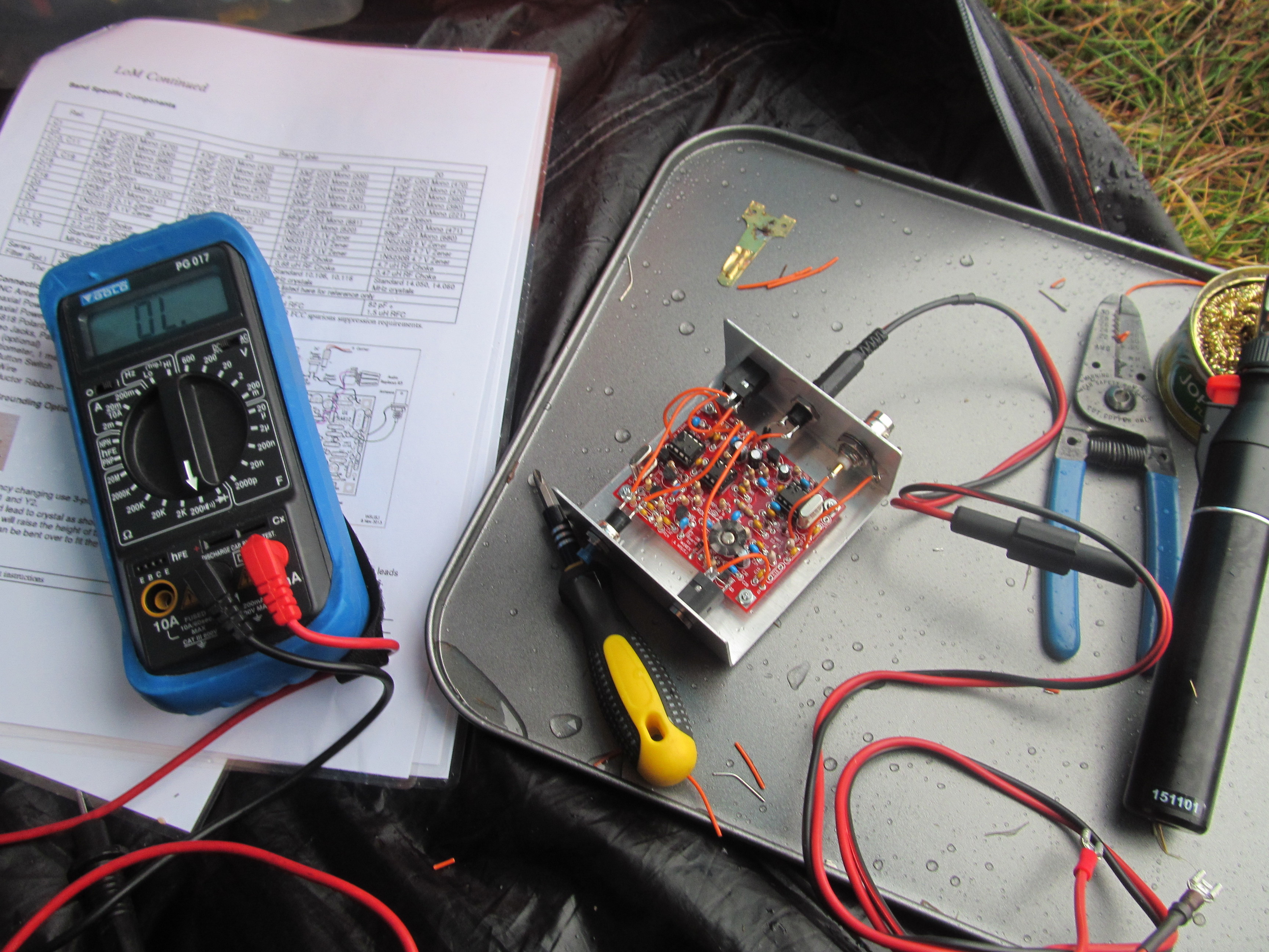
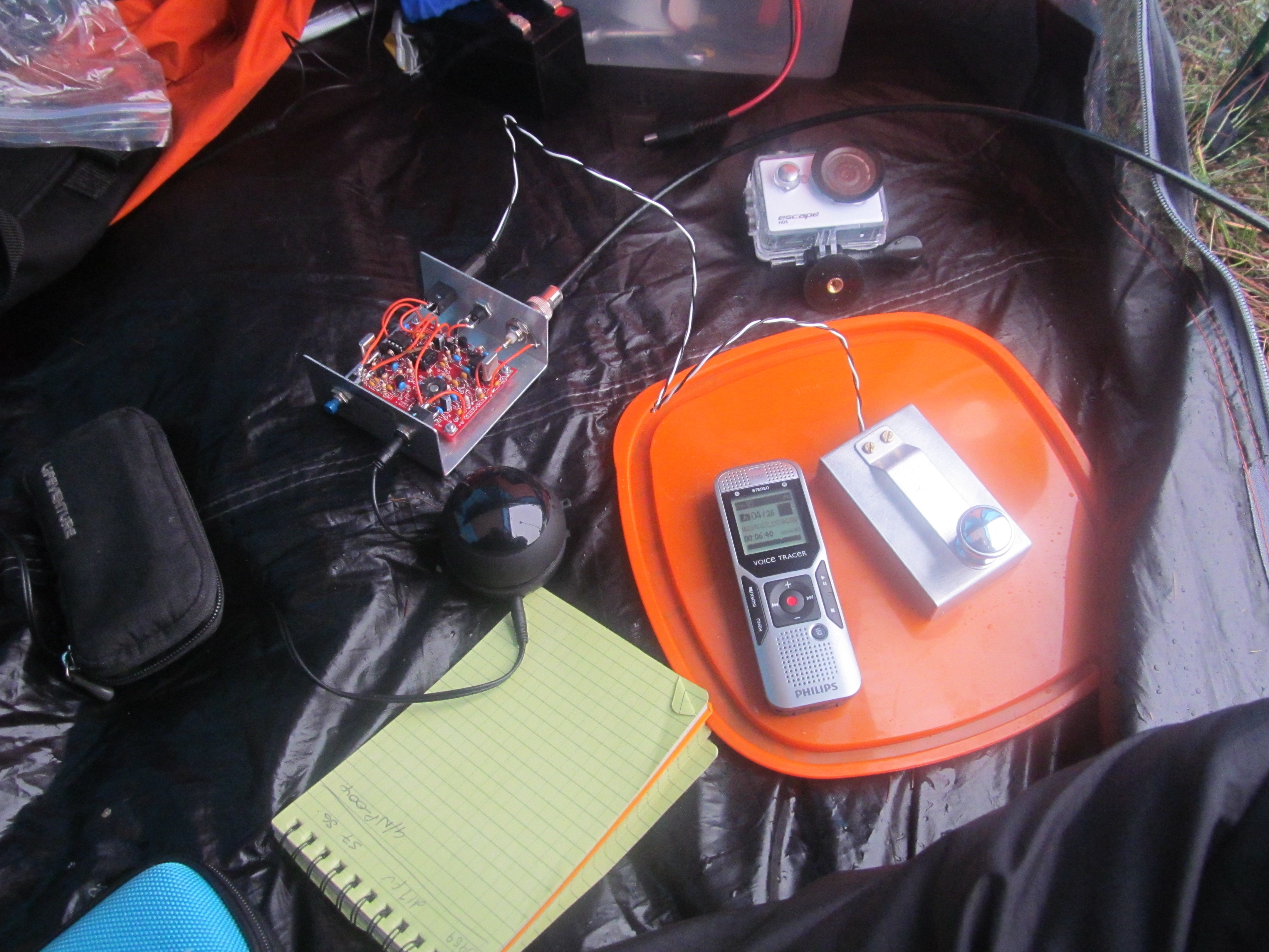
The kits went together well and the RockMite fired up first time without any debugging, although the building took much longer than I had reckoned.
I was late on air, but eventually Barry N1EU found me for my first contact. Shortly after followed SP9AMH, OH9XX and finally EU2MM to earn me my needed points. Mountain Goat was in the bag! The QSB was very evident today, QSO’s were tough, except with OH9XX, who was ear blasting. 
Firing up the FT817 (I intended to share my success with as many as possible!), I worked a handful more stations on CW and SSB, but my time was rapidly dwindling.
Finally, I’d like to say thanks for all the support given by numerous SOTA participants over the years, There’s a number of great, inspirational people we’ve lost in that time and I think about lots of them all the time. Roger G4OWG was particularly on my mind today as I learned of the route I took today from one of his posts. I never met Roger in person, but he was a keen chaser and fairly local to me.
73, Colin
Edit – I forgot to put forward my thanks –
Thanks to Dennis G6YBC (Kanga Products) for sponsoring a RockMite ][ ver. 1 PCB
Also thanks to Pete G4ISJ for supplying the solder!

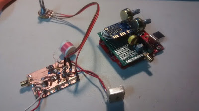
I was having a noise problem with my NE602 Si5351 OLED display receiver. There was an annoying high pitched whine in the audio output. The source was easy to identify: If I reached in and unplugged the OLED display, the noise disappeared.
Next I had to find out how the OLED noise was getting into the rest of the receiver. It could have been through the SCL SDA or even the ground lines. It could have been just through capacitive or inductive coupling from the display board itself. A big clue came when I tried powering the display from a completely separate power supply: BINGO! The noise disappeared. So I knew the noise was going into the rest of the receiver through the Vc line that powered the OLED.
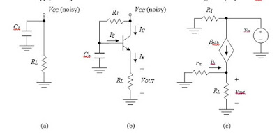
I had been powering the OLED from the 5V regulator on the Arduino Uno. In an effort to isolate the noise, I put a separate 5V regulator in the circuit for the OLED. No joy — noise still there. I then tried putting an RC low pass filter between the OLED and the 5V regulator. Still had the noise. Finally I remembered something from the AF AMP circuits of Roy Lewallen, Rick Campbell and Roger Hayward. ( I think Roy was the pioneer on this one.) They all used an “active decoupler” between the first AF amp and the power supply line. I confirmed that it was my first AF amp that was picking up the OLED noise. I built the active decoupler (just three parts!) and the noise disappeared. GONE!
There are only three parts, but the way this circuit works is kind of complicated and not very intuitive. There is a good discussion of how it works here:
www.facstaff.bucknell.edu/dkelley/elec351/Lab/elec351lab5_sp04.doc
Roy, Rick and Roger were using this circuit to knock down 60 Hz AC hum, but I found that my OLED noise was at around 200 Hz — I figured (correctly) that the active decoupler would take care of this as well. I think this little circuit can be useful in dealing with the kind of noise generated by the digi displays that many of us are now using.
David Rowe has a really interesting analysis of this circuit here:
http://www.rowetel.com/?p=4781
Hi Guys!
I have to admit something. It’s a learning experience.
A year or two ago I bought the Bitx boards from Sunil in India and while they are on the To Do list, haven’t been built up yet. I have close to 20 projects on my to do list, so when Farhan’s prebuilt SMT version became available I decided to get one.
I had gone over to TenTec before they shut down and bought a few of their two piece enclosures since I like how attractive they are and also inexpensive.
The Bitx went into the enclosure quickly and I measured a little over 10 W out with my scope. I fed a -125 dBm signal in using my HP8640 generator and could easily hear the tone.
So a really sensitive receiver. Nice and quiet too!
I got a SMT digital dial from QRP Guys and got it in the case. Now I heard a high pitched whine in the background. Nuts!
So I posted to the Bitx yahoo group asking for help in reducing the noise. I built a R/L/C filter network, added ferrites, built a copper clad and brass enclosure for the display. Nada. Noise still there. Adding adhesive copper tape didn’t help either.
This was driving me mad. For some reason, and I don’t know why, one evening I decided to try a gel cell. Success!!! No noise whatsoever.
Here’s what happened….
When I first built the radio in early December I tested it on my operating bench. On that bench is a older Power Designs 0-60V 0-5A linear bench supply.
After adding the display I did integration on my soldering lab bench and for that I grabbed my HP E3610 supply which it turns out is heavy but switching, not linear. The noise was coming from the supply!!
If I hadn’t tried the gel cell it may have taken me a long time to figure this out.
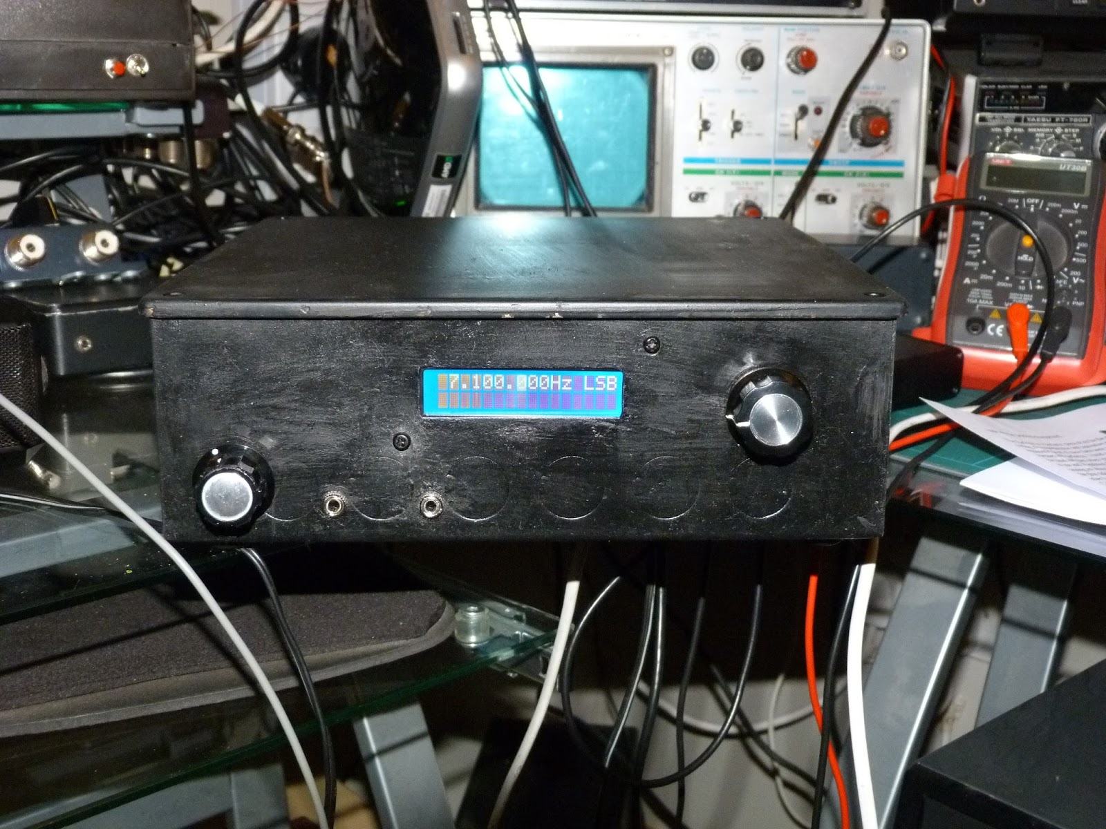
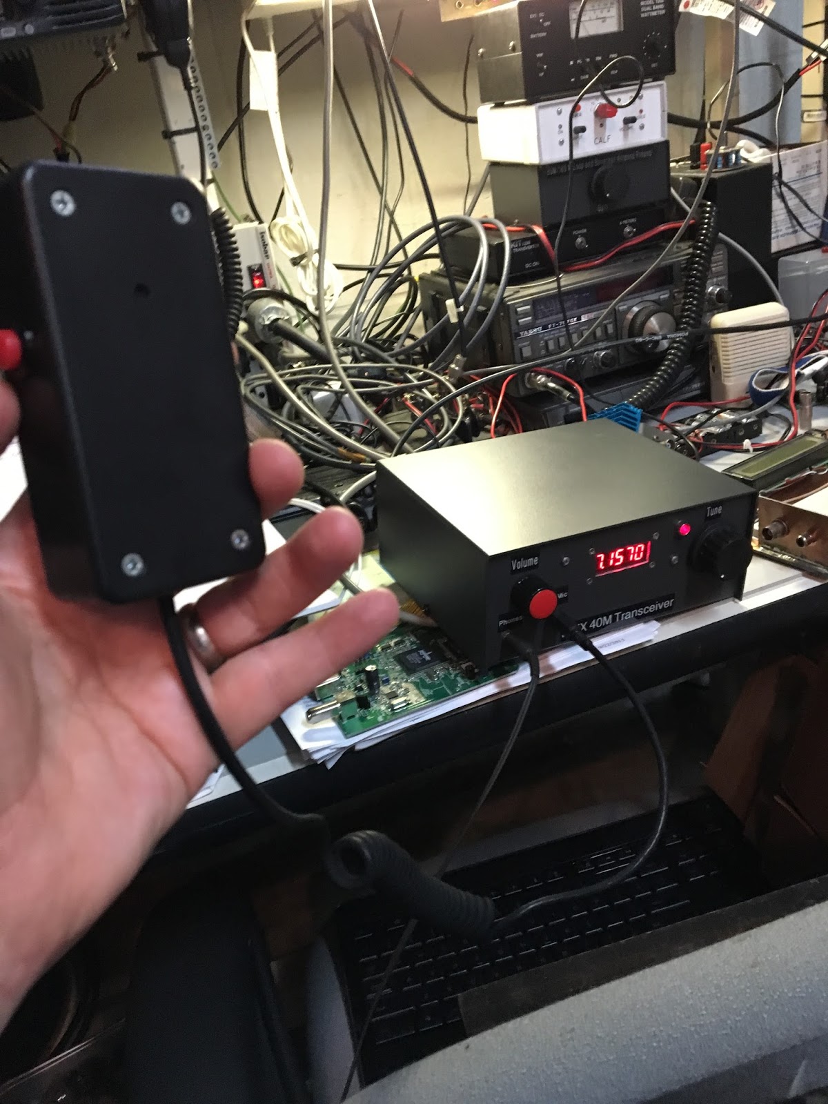
Saturday of last week was my first contact with it. I worked two Canadian stations with it, and both came back to me the first time after I answered their CQ’s. I did have one issue and that’s the well documented drift. During the QSO I watched the display drift upwards as I held the PTT button down. I replaced the 100 pF and 47 pF chip caps in the VFO with disc ceramic parts from Mouser and now it doesn’t drift.
While doing the work in the VFO section I also tweaked the trimmer cap a bit to bring the bottom range up to the start of the phone band, as before the bottom end was below 7 MHz and I figured that didn’t do me much good for a SSB rig to waste a lot of its tuning range on the CW segment.
Here are a few pictures. Mic is home brew too, having made it for my MMR-40 rig.
Hope all is going well for you and looking forward to the next Solder Smoke.
Chris KD4PBJ

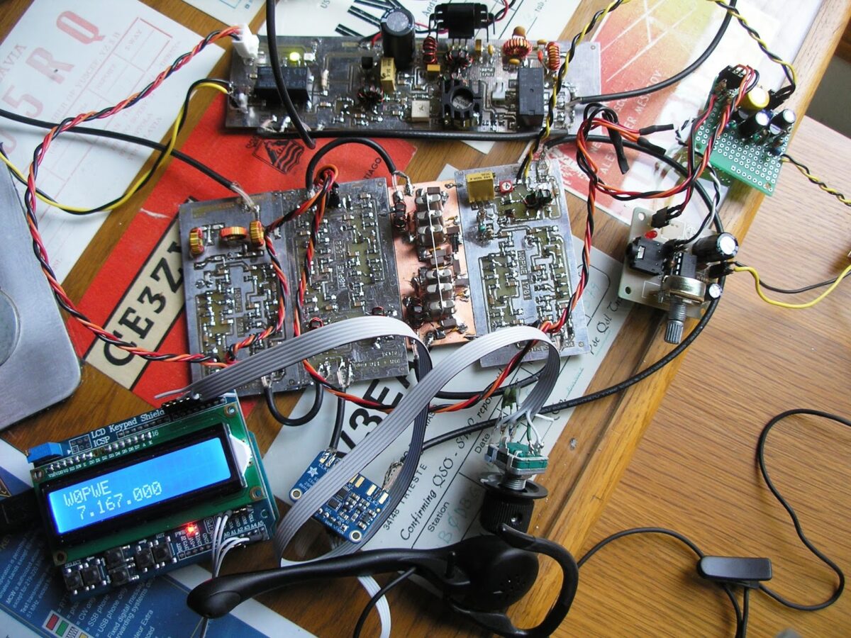
When I finished my first QSO with W9SX, Keith in WI N6ORS called me. He was running a multi-band Bitx he had built and we had a great HB2HB qso. Awesome!
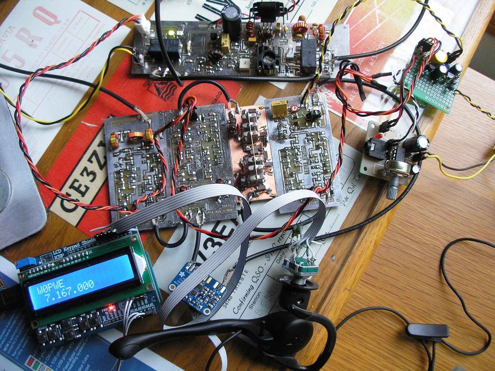
My rig is scratch built, mostly SMT and generally follows the 40M schematic that Farhan has on
his HFsignals page. I am using the Kopski/Hayward TIAs though and I designed a 6 pole crystal
filter for it since 6 of the 10 crystals I bought were very similar when I characterized them
with my PHSNA setup. It uses the Adafruit SI5351 board and I modified a sketch that LA3PNA wrote for the Arduino.
I designed and fabricated the boards for it using the software and process described by K7QO and
W5DOR. Toner transfer with the Hammerhill Gloss paper is working great. The heatsink on my IRF510 is a little light. I could smell the MOSFET warming up during a few of my lengthy transmissions with Keith.
Now the SWL report. While listening on the receiver portion of my Bitx last week I heard you on
7260 at about 0030Z. I think that was Tuesday or Wednesday. I wished I could give you a call but
at that point my PA was merely a few traces on the computer screen. Hope to hear you again on
40M.
73/72,
Jerry – W0PWE
Mike AB1YK built this very nice BITX20. On a board, al fresco. Very nice. He provides a good write up here:
http://n1fd.org/2017/01/18/first-homebrew-contact-on-my-scratch-built-bitx-20-ssb-transceiver/
I feel obligated to defend his poor analog VFO. Mike — that oscillator never had a chance OM! You need to nail that coil and that capacitor down! You threw in the towel and went over to the dark side way too fast. Go back and get that VFO stable.
Similarly, I’d say it is time to put away the keyboard and get out the microphone. This is a 20 meter phone rig after all. Allow it to send your dulcet tones across the seas!
But seriously, great job Mike. There are very few scratch-built homebrew SSB rigs on the air these days. Congratulations OM.
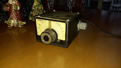
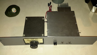
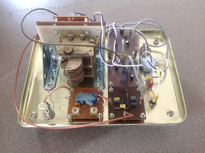
In early December Steve Murphy N8NM picked up this “mystery box” at a hamfest. Dr. Juliano identified it as an old CB VFO. Even though Steve is deeply committed to the dark side of frequency generation (digital synthesis) I was able to convince him to put this VFO to legitimate and proper amateur radio use AS AN ANALOG VFO. I mean just look at that dial! It would be a sin to connect that beautiful mechanism to a rotary encoder. We see the results below.
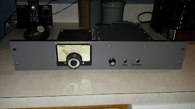
Bill:
The 30m rig that I had hoped to have QRV for SKN is finally ready to hit the airwaves! I still have a few odds and ends to tidy up, but it’s essentially done.