Not by me, thank God! No, the five years of Rasp Pi maso-tinkering were done by Thorin Klowsowski. His report appears here: http://lifehacker.com/what-i-ve-learned-from-tinkering-with-the-raspberry-pi-1793236686 In the second and third paragraph, he confirmed all my suspicions: The Raspberry Pi is far, far away from being as user friendly as a PC or Mac. That’s a feature, not a bug… Before hobbyists latched onto the Raspberry Pi, it was a computer for learning how to code targeted mainly at kids. Since then, the appeal has broadened, but it’s still impossible for a project to “just work” out of the box. You will have to tweak something, dig into the command line, or spend a few hours buried in an obscure internet forum to find solutions to problems that only you seem to be having. You will slam your head against the wall, yell a little, and throw your Raspberry Pi at least once for every project you attempt to make. I told you so.
Can’t say enough good things about your podcast – thanks for all that you do. I’m a fairly new ham and have been trying to go the home-brew route as much as possible.
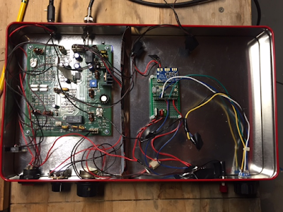
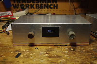
I bought a BITX40 module (pre Raduino vintage) and added my own VFO board using the usual parts. Actually, I’m using a Teensy 3.2 instead of an Arduino because it is a faster part and has a lot of DSP functions built into it that I’m using for digital mode stuff. But it’s the same basic idea.
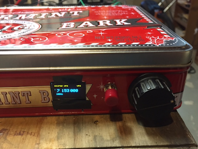
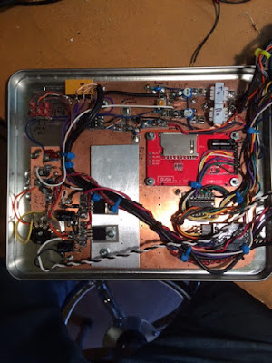
My BITX40 is not as photogenic as some of the others, but I sent a picture below. This is the “biscuit tin” variety. It’s was funny actually: a co-worker of mine stopped by my office around Christmas to give me a gift and pulled out of his bag a very nice box of “peppermint bark” candies with a ribbon around it. The VERY FIRST thing that crossed my mind the instant I saw the gift was …. BITX40 ENCLOSURE! He must have been pleased to see the huge smile that came across my face. 🙂 I’ve been bitten by the bug for sure.
My first three HF QSOs (ever) where on the BITX and were all very interesting:
First real QSO of my life was with KE4TJB “air-born mobile” off Delaware. He is a commercial pilot flying for JetBlue and apparently has time to work QRP stations during flights?? I wonder who was flying the plane?
Then I was scanning around this morning and caught K4HW making last calls for check-ins on a net running on 7242 out of North Carolina. I decided to give it a shot, having never joined an HF net and I was recognized! As the first round got going I realized I had joined a Jehovah’s Witnesses net. They were very friendly and the net control stopped to help my get my frequency calibrated before they continued with the scripture passage for the week.
Later this morning I reached K3KLC in Maryland who had the high-end SDR rig with the waterfall/panadaptor/etc. Remembering comments that you guys have made about these types of folks on 40m, I was very concerned. But this guy turned out to be very helpful and sent me some screen shots showing what my signal looks like.
Bill, Pete: I wanted to update you on my DC receiver progress. While I’m still operationally proficient in CW, many of my friends are not. So I thought it would be fun to add a CW decoder to my DC receiver.
In my research for a solution, I ran across a sweet decoder I thought might be of interest to the SolderSmoke listeners. OZ1JHM developed a totally software based decoder for Arduino that uses the Goertzel Algorithm. This algorithm performs similarly to a Fast Fourier Transform but only for tone decoding at specific frequencies. This limitation keeps the code small and fast making it perfect for microcontrollers like the Arduino.
I was able to hack Hjalmar’s code into mine and the result is CW decoder functionality in the receiver with no additional hardware! But, the Arduino Uno’s performance is limited so I need to dynamically switch between receiver VFO/control code and the CW decoder in order to preserve real-time performance. This is only my first pass so perhaps I will find a way to optimize the code to more fully integrate the two. I currently switch back and forth based on whether the VFO knob has been rotated or is idle. This at least gives the illusion of real-time integration but makes it harder to tune in a signal for the decoder.
Now that the Arduino Zero is available, I’ve been considering moving that direction to dramatically improve available horsepower. This isn’t the first time I’ve run out of gas with the Uno. Now it’s time to start working on a transmitter module for the radio :). You know, even though I have an operational K3, I find myself reaching for this radio first. Something magical about using something you’ve created :). But hey, preaching to the choir!
(Link to video appears below.) Stephen G7VFY sent me the link to Mike WU2D’s Retro-QRP video. In the last month spoken to Mike at least twice on 40 and 75 meter AM. Stephen was responding to a post I did about a 1958 18 milliwatt solid state QRP rig.
Mike’s video is really wonderful. I’ve never been into military surplus, but this video made me think I might want an ARC-5. The rig Mike builds and tests is very similar to our beloved Michigan Mighty Mite. His description of the build and the testing procedures he used will be of great interest to those who’ve built the MMM rigs. And he made some contacts. Finally, there is a cameo appearance by Paris Hilton. And she is holding a HOT transistor! Wow!
Mike has a real talent for making these kinds of videos. Thanks a lot Mike — see you on 40. And thanks Stephen (Stephen has sent us so much great stuff over the years, including a fantastic box of British valves.) Pete: See how nice it is to get back to QRP? Here’s Mike’s YouTube Channel. I love the intro: https://www.youtube.com/channel/UCN7RQv_qmzhzuJV1HhJ4OEA
SolderSmoke 194 is available (scroll down for link) March 4, 2017
BIG NEWS: uBITX from Farhan
BENCH REPORTS Pete: Recycling Old Boards Working on Arduinos and advanced displays
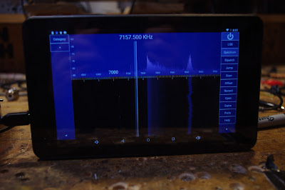
Bill: SDR Adventures and Misadventures. RTL-SDR is fun. Built HB front end. HDSDR under Windows is fun and easy. Thought about Raspi3, 7 inch touch screen, Linux, software YUCK. Followed advice of Ken G4IIB and got a 50 buck tablet with Google Play.
Who needs tiny OLEDs? Use a 7 inch tablet as your display!
Building a Ceramic Resonator for the HRO 455 kc filter The value of doing something different. Boxed up my NE602 OLED rig. OLED noise and ACTIVE decoupling. NE602 and MOSFET tips
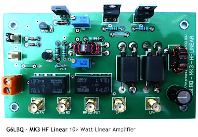
LEXICON: OTD Obsessive Tinkering Disorder G6LBQ “A Thing of Beauty” Source of Tombstoning term: Don ND6T. Ken G4IIB’s extremely smooth audio.
ON THE AIR: On AM on 75 and 40. Fun. Old Military Radio Net and “The Lonely Guy Net” on 75 Saturday morning. Good old 17 meters. Open at mid-day HB2HB on 40 with W0PWE. Listening on 60
Hambrew magazines disappeared, but are back now. EMRFD Classic Edition available New Posts to BITX HACKS
MAILBAG: Gloves follow-up. Not a good idea. VK3YE’s QRP by the Bay event and a new book! Colin M1BUU achieves Mountaingoat status Martin A65DC JoO MMM in the UAE Tom NY2RF Editorial with mention of JoO! Lots of Al Fresco rigs: W8LM BITX on a board, Brad WA8WDQ DC RX, KA4KXX Al Fresco OZ DSB ON6UU DSB from Spain via Belguim Hugh ZL1UEM SMALL Si5351 OLED Cookie Tin rigs VK2EMU’s Biscuit Tin DC RX, WA7HRG’s Popcorn rig VK4FFAB FB LTSPICE intro Ken G4IIB’s BITX adventure (with VERY smooth audio. How smooth? We can’t say.) VU2XE’s BITX with a CAD box G0ETP’s shockingly beautiful SDR receiver Alan W2AEW on the mend with broken ankle. His videos are a treasure trove of tribal knowledge.
From the earliest BITX articles, Farhan has encouraged the use of discarded cookie or candy boxes. Jim’s popcorn box is clearly in this tradition. There is also, of course, a connection to the idea of using simple “popcorn” transistors.
Popcorn Radio
by Jim Purvis WA7HRG
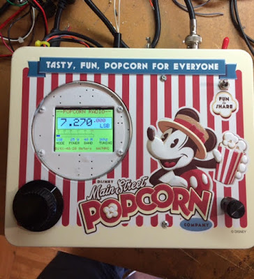
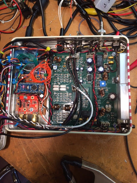
While celebrating Christmas and a Birthday at Disneyland in Dec., my wife and I enjoyed a box of popcorn during one of the many parades. It was too nice a box to toss in the trash so I brought it home. It kicked around the QTH a few weeks until I caught the BitX40 v.3 fever. Wow, just enough room for the BitX and a few hacks, and the project was on. And a very neat way to remember our good time at Disneyland.
I decided on several hacks and mods and made a list. In the end I settled for less. Hihi
1.Switchable 5 or 20 watts out.
2.Single power supply. 24 volt PA with a 13 volt regulator for the rest of the radio.
3.Dual band. 40 and 20 meters.
4.SSB and digital mode operation. Built in audio interface and sound card.
5.A tune function for antenna adjustments.
6.On screen S-Meter.
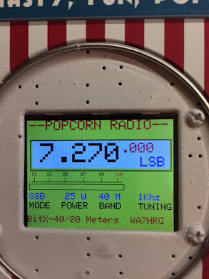
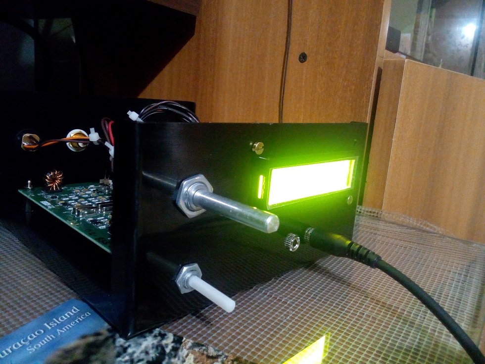
7.2.2” color TFT display. Because I can display more information and it’s just cool. The Radino it came with was set aside for another project.
I had a 24V 5amp laptop power supply as the base supply. I used two 7812 regulators in parallel and an aluminum plate heatsink and raised the common a little above ground for a 13 volt output. I could then switch that between 24V for the PA. Regulators get a bit warm when using them in the 5 watt position so most operation will be at 20 watts.
Dual band operation was soon abandoned simply do to space limitations in the box. I had no room for additional BPF and LPF.
The audio interface not only provides ground isolation and level control between the PC and the radio it also provides a VOX operation for digital modes. The digi software can provide the PSK (or other modes) audio on the left audio channel and a continuous tone on the right. I use this for the VOX operation. A ‘thumb drive’ size USB sound card provides the connection to the PC with just one cable.
Antenna tune function was provided by a version of Pete’s LBS method and I just used a small relay and a push button to activate PTT and to unbalance the balanced modulator.
The S-Meter proved problematic for me. I might not have had it if not for help and advice from Pete. It may not be accurate but provides a good relative signal strength indication. And looks very cool!
The DDS is a quagmire of several different sketches and some of my own coding. This was my first adventure into actually coding the sketch from (almost) scratch. I am sure I am very close to the maximum times you can program an Arduino as my “Guess and Test” method of coding became very arduous. All switching of mode, power and other functions are done at DC allowing me to use that as inputs on the NANO to change DDS function and displays.
All and all I am very pleased with the way it turned out. Not sure what I’ll do about losing 20 meters. Hmmm guess I’ll just have to build another radio. J
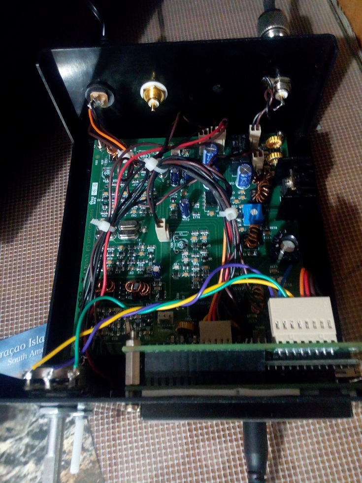
Front cover. Upper Right corner is the Digi/SSB switch. Tuning and vol are at the bottom. All controls and switches were located, sometimes in odd places, to retain the graphics of the box.
In the lid. Upper left corner is the digi/SSB switch and across the top is the audio interface ckts. TFT is in the middle Right. Below that is the 3.3v level shifter and encoder. On the heat sink are two 7812 regulators in parallel. I raised the common a little above ground for 13v out. Far left is the vol control and S-Meter amp and det ckt.
The main chassis. Across the back left to right are power input, spk jack, mic/PTT jack, ant connector, and 5/20 watt switch. Far right is the PA heat sink. A 1x.5×4″ aluminum bar. It’s what I had… Lower right corner is the tune push button and if you look close in the upper left corner of the main board is a mini relay glued to the board near the bal modulator. That unbalances the modulator and provides a carrier for antenna tuning. Upper left of the box below the power connector is the USB Sound Card for the PC interface. And a couple extra input wires I ended up not using. Below that is the standard Nano and si5351.
Last but not least is the 2.2″ TFT. All functions power, mode, etc., are DC switched. I also use that as inputs to the Nano for display changes. I sense the 12 v relay voltages and through a voltage divider to input pins.
It has been a fun project and I can continue to play with it, but I think its time to button it up and use it a little.
It’s back to my General Coverage Rec that I started but never finished.
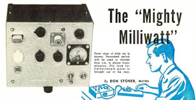
I think it is time that we get back to our QRP roots. Perhaps under the influence of the wizard of Newbury Park (N6QW), we’ve all been drifting into the world of high power. It starts innocently: you hook up a second gel cell to the IRF-510 and suddenly you are at 20 watts out from the BITX. Before you know it, you have an uncontrollable urge for 3-500Z’s. Here is a story that will get us back on the QRP track: It was September 1958. On the 14th of that month I began my first orbit of the Sun. Band conditions were VERY good. OM Don Stoner was on 10 meters with a homebrew solid-state milliwatt rig calling CQ TR, CQ TR (CQ Transistor). Jarno PA3DMI in Amsterdam sent me the link to a Radio News article by Don Stoner. The article (and the entire magazine) is a lot of fun. Check it out. The QRP fun begins on page 51. Thanks Jarno! http://www.americanradiohistory.com/Archive-Radio-News/50s/Radio-News-1958-09-R.pdf
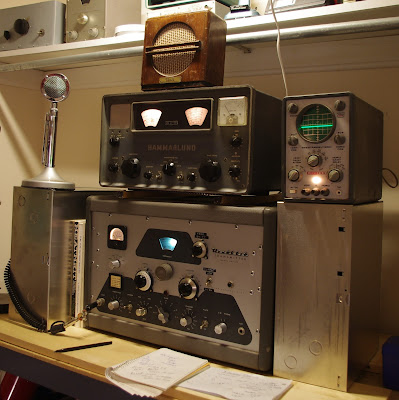
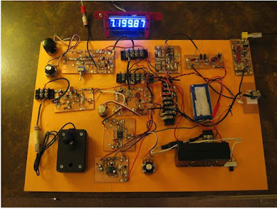
Steve VE7SL recently discussed Heathkit’s wise use of the color green in the VF-1 and DX-100 frequency readouts. The power of green is visible in the above photo of the N2CQR AM station. (I used this gear to check into the Old Military Radio Net and the Lonely Guys’ Net on 75 meters on Saturday). Note the VF-1 on the shelf in the upper left, and the awesome green oscilloscope trace. Juliano Blue is all well and good, but let’s not deny THE POWER OF GREEN. Steve’s discussion (and cool Knack story):
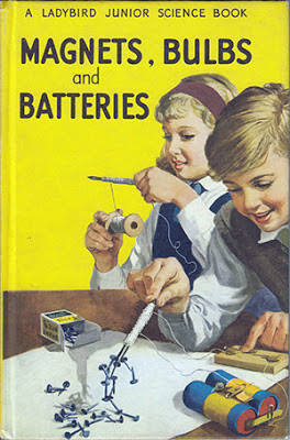
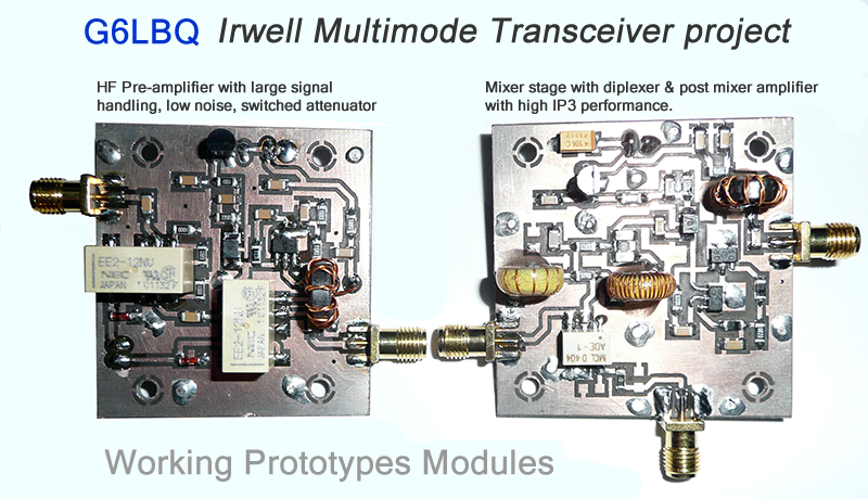
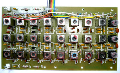
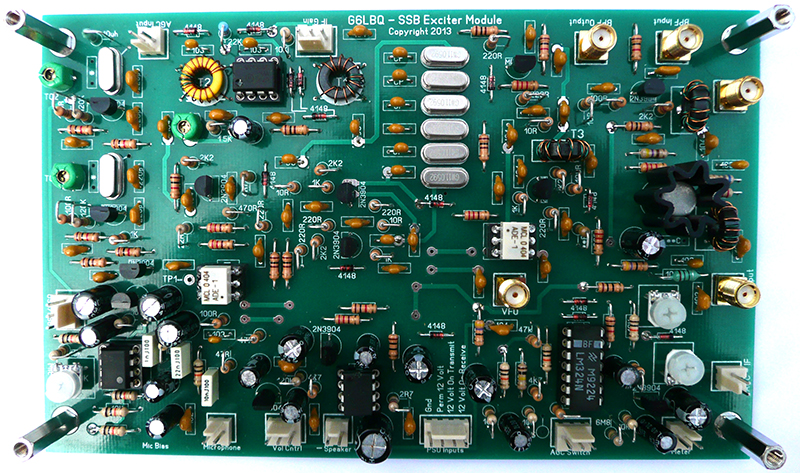
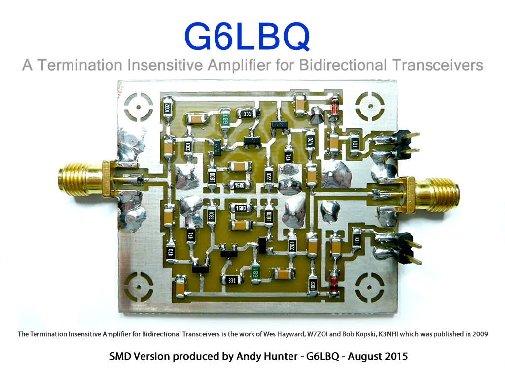
The early fascination with small light bulbs, switches, and batteries confirms the diagnosis. The Ladybird group seems to have led many a young British person down the path to OTD (see the web site for more info on this malady). https://g6lbq.blogspot.com/ Andy writes:
Hi Bill
I have built a few BitX transceivers and developed a 9 band version which has been built by various hams around the world.
Always look forward to the SolderSmoke podcast which I enjoy immensely.
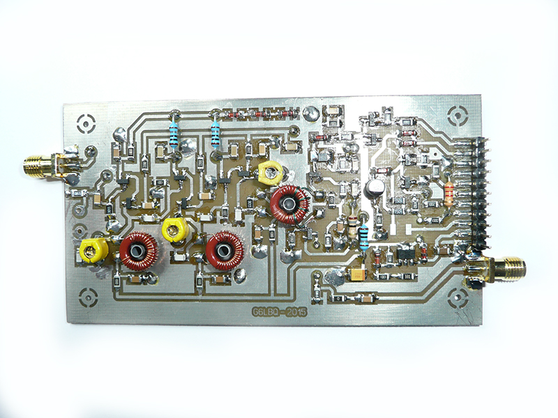
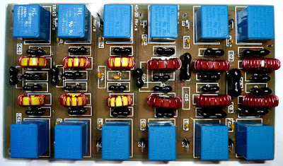
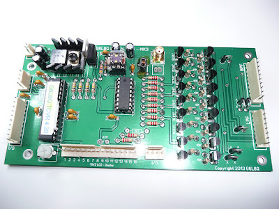
For your interest I have attached some pictures to show you some of the modules I have designed/developed and built for my Multi-Band projects. The SMD boards are for my latest project which I call the Irwell Transceiver, my intention is to make it all band HF and multimode.
Hopefully my pictures will meet with the SolderSmoke approval and the inauguration can take place for recognition that I officially have The Knack, failing this it will be a Basta moment at the G6LBQ workshop!
Keep up the great work you do with SolderSmoke which brings pleasure, fun and inspiration to hams all over the world.
Maybe some interesting news for you as there are some new kits at hand from EA3GCY (http://www.ea3gcy.com)
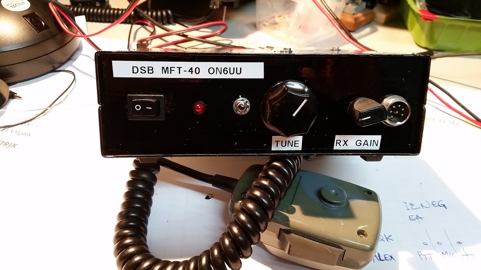
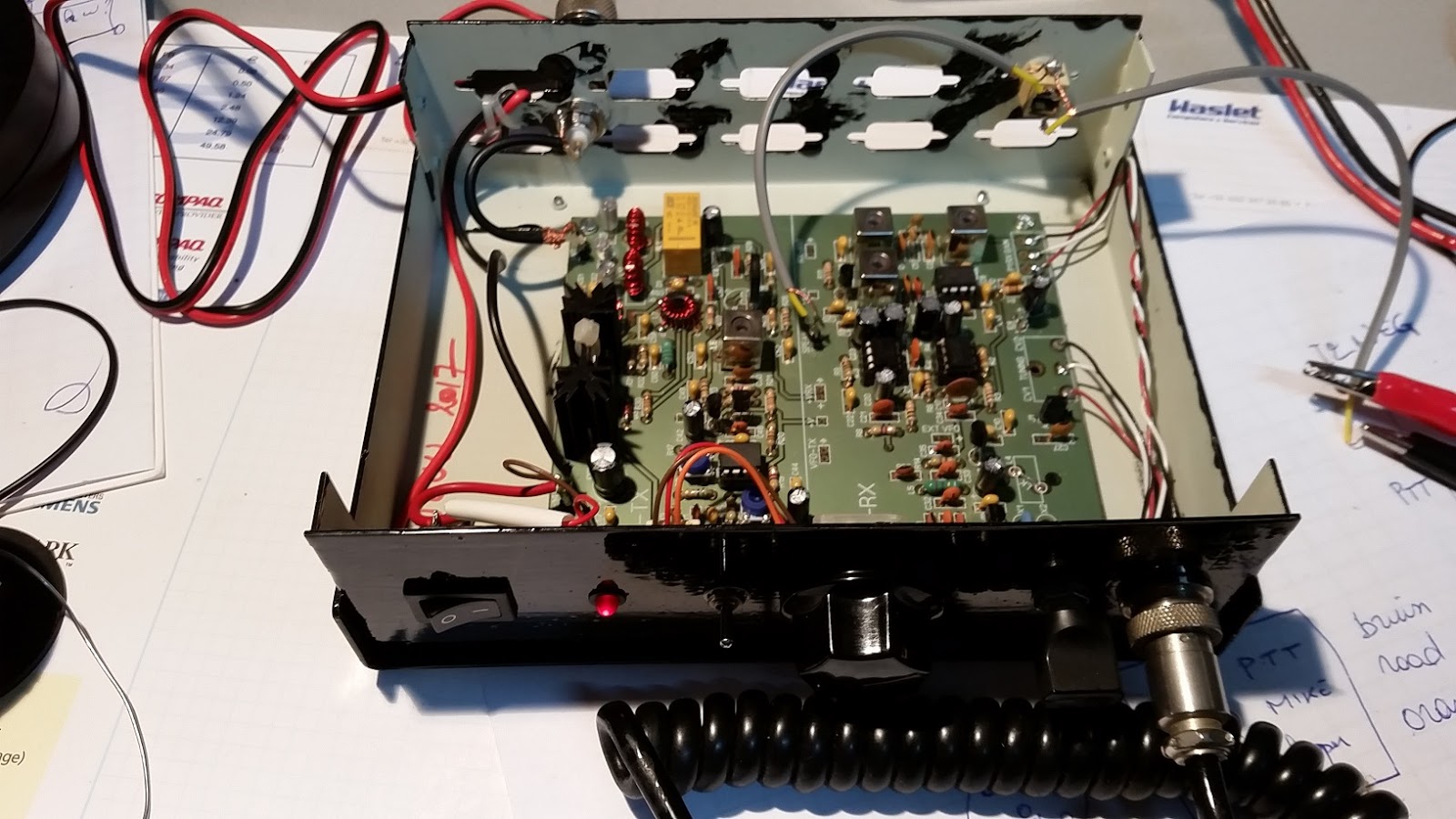
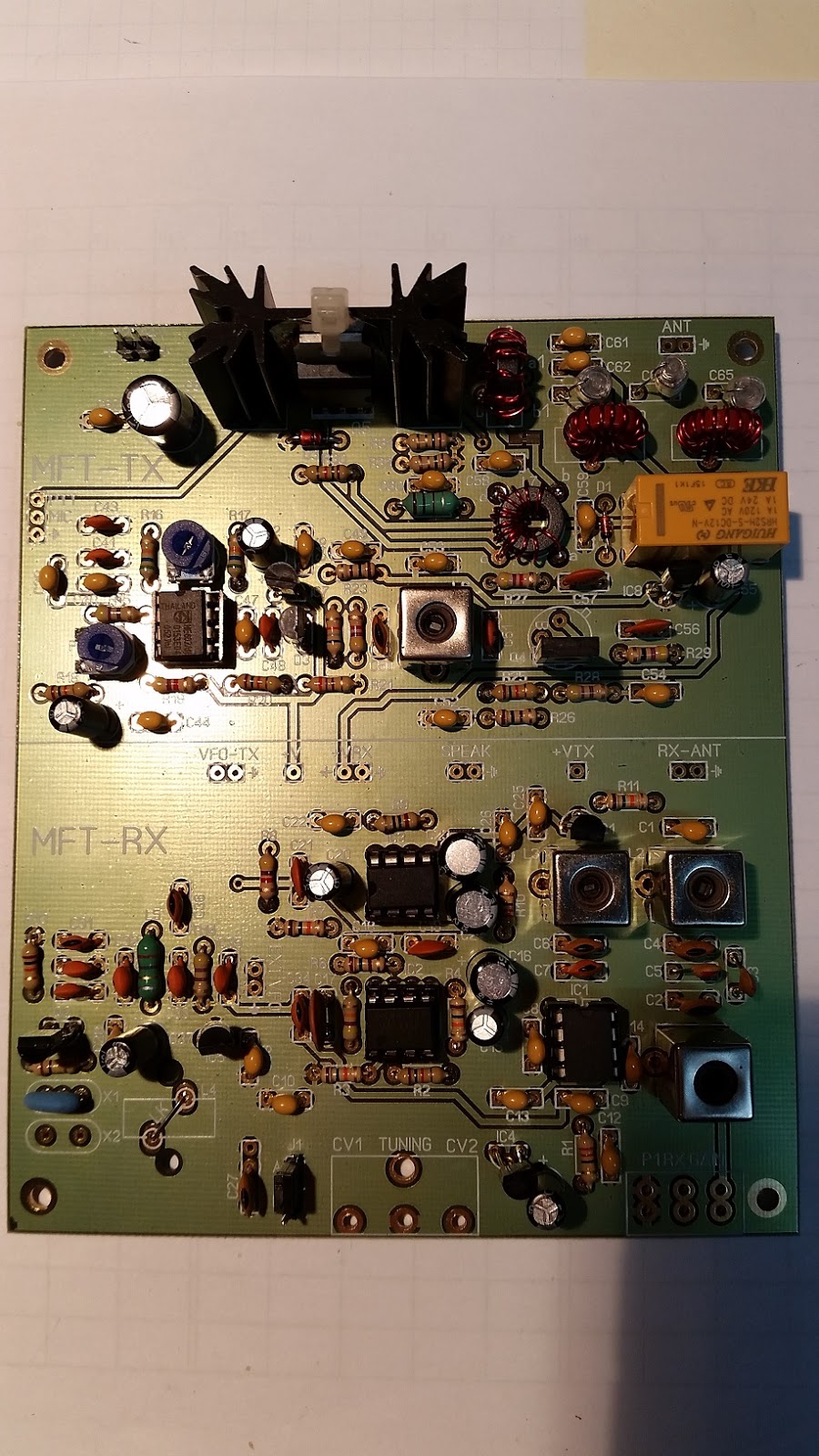
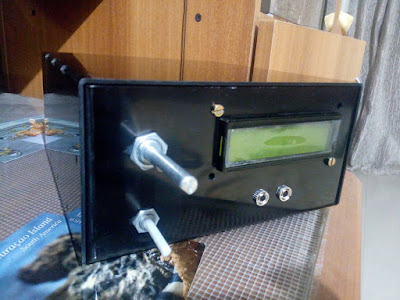
I’ve made the MFT-40 DSB without any problem, all parts were provided with the kit, only things to buy were a microphone connector, a speaker and an antenna plug. The box was taken from my attic and was a VGA-selector in his previous life.
Kit came together in a few evenings, I followed the very well written manual, all was well pointed out, which resulted in a working kit. After aligning the kit I could start making qso’s. The microphone was made from a piece of tube, a simple switch and a electret microphone, it doesn’t look pretty but the microphone works.
Rx-Tx 7.066 – 7.133 (With DDS the complete 7MHz band)
Easy to make, no SMD, easy alignment without necessity of expensive material. Fine for someone who never made a transceiver, hence the name…My First Transceiver, MFT. As soon as the weather permits I will take the TRX out in the field and activate a SOTA with it.
Now working on the MFT-20 DSB. I’m hoping for an 80mtr version to come available too. 🙂
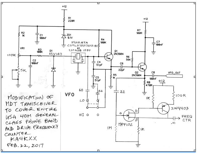
A while back we ran a post about the MDT 40 DSB rig out of Australia. Walter KA4KXX liked the design so much that he built his own version and, with it, made his first homebrew phone contacts. I always say that DSB is a great way to break into the world of microphones. Walter is obviously on the right path — not only did he come up with a nice Al Fresco DSB rig, but he modified the VFO to get additional coverage and to incorporate a frequency counter. FB Walter! Walter KA4KXX writes: Since I earned my Ham Radio license in about 1979, I have always operated only on CW since I like to build all my own equipment, but recently at the SolderSmoke website I discovered the MDT 40 Meter DSB Transceiver, and decided this was the design I had always been looking for to finally build and operate on phone. After I made my first phone contact after only 5 minutes of trying, just a few weeks ago, I was so excited I sent an email thanking designer Leon of ozqrp.com.
Then I modified the VFO further to cover the entire 40 meter USA General Class License phone band, which is 7.175 – 7.300, in two overlapping steps. I also added a 5K fine frequency adjustment, used a more friendly 1SV149 Varactor diode which I purchased on EBay at very low cost, and also added a high impedance buffer (found at the website listed below) to the VFO to drive a frequency counter. http://www.arising.com.au/people/Holland/Ralph/buffer/highimpedanceprobe.htm I was able to implement these modifications very easily since I always make my own un-crowded state-by-stage Manhattan style circuit boards and build first on a breadboard. So far I am very pleased with the results.
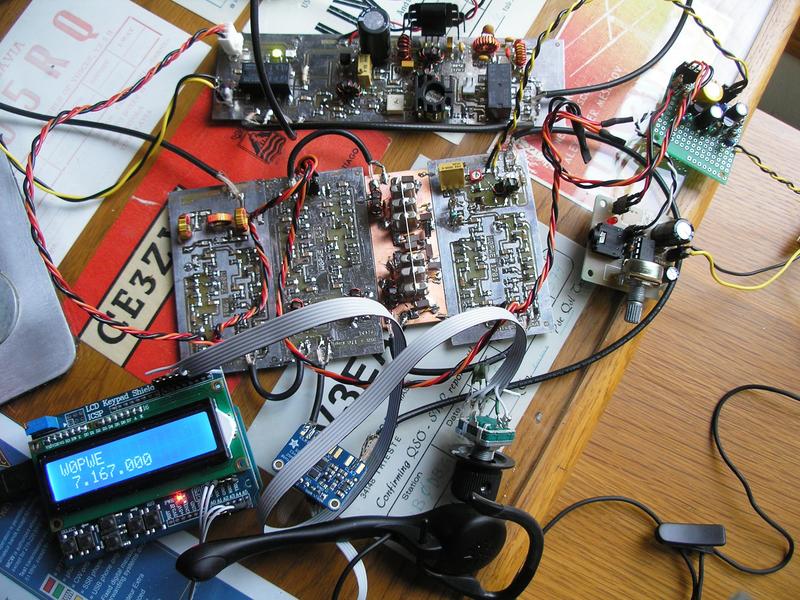
I got on 40SSB this evening and called CQ with my BITX DIGI-Tia. Hooray! Jerry W0PWE answered me with HIS 40 Meter DIGI-TIA. His is still Al Fresco style. Very nice. We add this to the homebrew to homebrew scorecard. Thanks Jerry!
A year or so ago Pete and I encouraged Kiran VU2XE to try the BITX. He followed through, on our suggestion and went a step further, using CAD to design a box for the BITX.I will try to post a link to Kiran’s CAD files on the BITXHACKS blog. Kiran writes: Hi Bill and Pete,
It is almost year since you seeded idea about the BITX. I am still a listener of your podcast.
After finishing my RF amplifier project late last year, I was thinking of few projects and BITX was on the top of the list. I ordered and received a very beautiful BITX40 kit with Arduino, I got it recently. I also designed a simple case for it using CAD software. It can be used by anyone — just go to your local laser/CNC shop to get it cut in Aluminum. I just thought of sharing the excitement with you. This rig and it sounds awesomely good 🙂
Attached are some snaps and design files (I am no expert in CAD etc. it is my first attempt to learn and build)
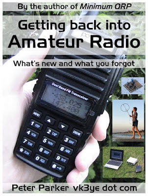
Homebrew Hero Peter Parker has a new book on the market. I was really taken by his description of the joys of restoring older gear. Peter really nails it. Here is an excerpt:
Vintage Equipment
The collection, restoration and use of historical equipment is another movement in amateur radio. The musty smell of warming dust, the heavy clunk of rotary switches and the velvet smoothness of precision tuning drives are joys of every use. Such sensuality is absent from modern plastic-fronted, wobbly-knobbed transceivers. Old rig cabinets felt they had something in them. A kick would hurt you more than them. And etched panel markings confirmed they were built to last. Unlike today’s dainty push buttons with stunted travel and disembodied beep, toggle switches showed you where they stood. Weight, life and play made adjusting controls for nulls and peaks (as often required) both a pleasure and occasional frustration. Even if only as mechanical backlash on a bad tuning dial, it was as if the equipment was telling you something, like a ridden horse does through its reins. Not like newer gear’s lack of tactility which is like a ‘dead fish’ handshake, all take and no give. There are psychic as well as physical joys. The thrill of bringing neglected or dead equipment to life drives many. It’s an underestimated skill. You start with nothing and almost anything done represents progress when building from scratch. Whereas with a repair it is very easy to render something that’s 80% good completely useless with a careless drop or slip. More about ‘Getting back into Amateur Radio’ is at http://home.alphalink.com.au/~parkerp/gettingback.htm & the video at https://www.youtube.com/watch?v=g4ktP5K4x-I
Earlier this week I shocked Pete Juliano by telling him that I was taking a break from my normal analog, discrete component, no-chips mode of construction so that I could put together a Raspberry Pi-based SDR receiver. Even from 3000 miles away, his astonishment was clearly perceptible. He seemed briefly disoriented by it. I’m sure some of you may have a similar reaction. I’d been lured in by that video of the Raspberry Pi RTL-SDR receiver with the very cool touch screen display. It has a waterfall! And a touch screen! How could I resist? I went to Amazon, but there I discovered that that attractive display is not exactly cheap. And maybe I’d need a new Raspberry Pi. At this point, in search of economy and convenience, I began rummaging through my digital junk box. There I found a Rasp Pi Model B. And an old computer monitor. This will be easy, I thought. Just get some SDR code into that Pi, hook up the RTL-SDR dongle and Bob’s my uncle, right? Not so fast. I quickly began to run into daunting digital obstacles. Sure, the Raspberry Pi fired right up and filled the computer display with lines of code. But it was all Linux. Yuck. Sorry Linux fans, but for some of us mere mortals, Linux is a weird opaque world in which every little thing is somehow a lot harder. I also began to suspect that my 2013 Model B might be sort of a Model T in the Rasp Pi world. It might not be up to the computing task. And finally, as I poked around the internet, I began to conclude that the Raspberry Pi software for SDR is not quite done yet. All the sites seemed to have the word “experimental” in there. And lots of “I’m pulling my hair out” comments Maybe I’m wrong, but maybe we just need to give this more time. Let me ask the distinguished group some questions: Is my Model B really useless for SDR purposes, even if I don’t need all the bells and whistles? Is there an SDR program that can be easily placed in a Raspberry Pi by someone who has NOT mastered the mysteries of Linux? For now, I have cleared the raspberries from the bench and am back to working on HDR stuff.