
Very cool video. We have visited VE7ZWZ’s amazing shack before. This time he takes us inside a BIG commercial AM transmitter that he has modified for use on the amateur bands.
I know that he had the plate voltage turned off, but I still felt myself cringing when he reached up to touch the plate connectors on those enormous thermatrons. The filaments were on, adding to my unease. Dude, don’t do that! And if you are standing INSIDE the transmitter, keeping one hand behind your back might not be as beneficial as it normally would be.
His comments on his VFO were interesting. I was kind of disappointed that he went with a varactor circuit. A varactor? Amidst all those bread slicer variable caps? It just doesn’t seem right. (And BTW they are bread slicers, NOT “potato slicers.”) But I kind of liked the heater–thermistor–insulation set up that keeps the VFO at constant temperature.
I thought it was interesting that these transmitters were kept on, with the tubes glowing for years at a time.
Thanks Mr. Carlson, for another great video!
Author: Peter Marks
Very Useful Toroid Info Web Site
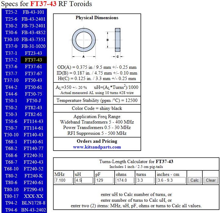
This site provides the kind of info we need when working with toroids. It even tells you the length of wire to cut. It links to the W8DIZ “Toroid King” website, but I can’t really tell if this site is the work of DIZ himself. In any case, very useful. We award this site our coveted rating of “Five Soldering Irons.”
Video of a REAL Homebrew QRP Contact (by WU2D)
I think Mike’s video does a good job of showing what it is really like to get on the air with simple, homebrew QRP gear. It takes some patience and operating skill. I guess it is sort of like fly fishing (with home made lures); there are easier ways to catch fish, but they are not as rewarding.
Discrete Dead-Bug O’scope Pong
Thanks to Bent KD0GLS for alerting us to this excellent example of the awesome power of discrete transistors and dead–bug construction.
Check it out. There is a video.
Another Excellent QRP Video from WU2D — Retro Solid State QRP Receivers
Hot Water BITX 40
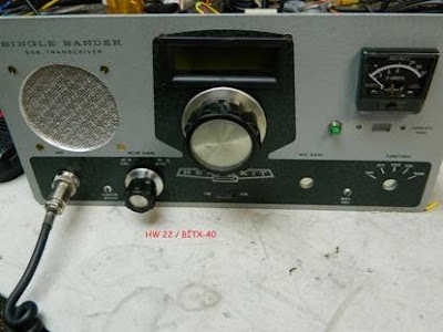

Fred’s idea really resonated with me. My first SSB rig was an HW-32A, the 20 meter version of the rig shown above. If — as I suspect — these rigs are anything like the HW-101, they are not aging well. Heath’s drive for economy resulted in rigs that don’t hold up to well over time. I remember the sound of the plastic HW-101 dial clutch cracking when I pushed the button.
BITX40 Modules to the rescue! Put a mono-band board inside an old mono-band rig. There are a lot of possibility here. Some ideas:
— Put that Heath VFO to use. Maybe convert it to solid state. Or just put the LCD from an Si5351 in the window (Pete did this with an HW-101).
— Get the S-Meter wiggling.
— Keep the final amplifier circuitry in there and let the BITX drive it. This will give you a QRO option. (Uh oh, we’re in trouble again!)
Hello Fellows,
Attached is a picture of my BITX-40 V3 adapted to a Heath kit Single Bander HW22. This is a work in progress but what a neat way to bring an old boat anchor into the present.
The only parts of the HW 22 used were the front panel and case and knobs. Modifications yet to be incorporated include: AGC , a USB port on the front panel to access the Arduino, and a PTT/CW mode switch.
I enjoy your pod cast and web site…Best of 73 KC5RT.
Hearing the Roosters from Boa Vista, Brazil
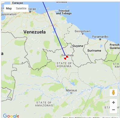
The ham radio day got off to a good start at N2CQR yesterday. 40 meters was open in the morning and PV8AL was calling CQ. Helio had a strong signal, due in large part to his 3 element 40 meter yagi. Helio lives on a farm outside Boa Vista, Brazil. As he spoke, I could clearly hear the roosters crowing in the Amazonian dawn. Very cool. It brought me back to mornings in the Dominican Republic, and in Central America. It also reminded me of one of my first DSB contacts from the Azores — I could hear the parakeets of Amadeu CT2HGL in Coimbra, Continental Portugal. Obrigado Helio! Obrigado Amadeu!
Fast Radio Bursts and the Molonglo Radio Telescope (with video)
7,744 circular dipoles on 843 MHz feeding 176 preamplifiers and 88 IF amplifiers!
Read about how the Molonglo Radio Telescope has recently been used to study the mysterious Fast Radio Bursts:
http://www.sciencealert.com/confirmed-mysterious-radio-bursts-detected-by-astronomers-really-are-coming-from-outer-space
There is a Grote Reber connection:
https://en.wikipedia.org/wiki/Molonglo_Observatory_Synthesis_Telescope
SolderSmoke Podcast #195: (We need some help!) BITX, 60, SSB History, Tribal Socketry

SENDING IT BACK
SolderSmoke Podcast #195 is available. Link appears below (scroll down)
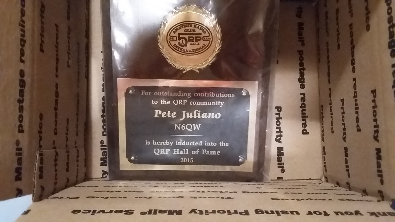
We’ve got a problem: Pete Juliano and the QRP Hall of Fame 🙁 PLEASE HELP!
BENCH REPORTS
Pete Releases Smoke (wiring harness)
Pete’s DifX on 60
Architecture and Dual Conversion (uBITX: uses ALL THREE clocks on the Si5351)
The Big Kahuna
ON HACKADAY with Philco SB100 SEE! QRP!!!!!
BITX60
Cap Stack Hack mod (with leads)
Let the smoke out of an Si5351 (shorted output) Several actually.
(Same day delivery zone for Amazon — but no drones or parachutes yet.)
Installed scanning switch
Observations on 60. All the weird bands have a 6 in them: 160, 60, 6
The good: 100 watt limit, wire antennas
The bad: Kind of cliquish– like 75, not much of a CQ band. Channels. Not much activity.
The bad: Kind of cliquish– like 75, not much of a CQ band. Channels. Not much activity.
Met Josh KE8CPD on 40. BITX 40!
TRIBAL KNOWLEDGE:
Socketry: How to keep BNC jacks from spinning loose?
Do you heat shrink?
Feel Tech Sig Gen might not have blocking cap at the output.
Speaking of which, when I spoke of the Ne602, I mostly meant blocking caps, not bypass caps.
How come they don’t have a cable TV channel devoted to radios? They have HGTV? Why not HBTV?
REPORT FROM WINTERFEST
Bad weather. Tailgaters wimped out!
Combined forces with Armand WA1UQO.
Met up with Charles AI4OT.
Acquisitions: 1/4 phono jacks, carbon mic, vero board, disc caps, weather radio,
LARGE collection of Electric Radios from Armand. Wow.
Electric Radio notes: 1st Fifty Years of Sideband 1991 articles by Jim Musgrove K5BZH
Why LSB on 75? — so AMers couldn’t follow to top of band
W2, W6, W8s liked phasing, W3, W4, W0 more into filter rigs.
Early SSB guys turning on carrier and talking AM hams into SSB RX.
Kelvinator Refrigerator rigs.
A reading on the homebrewing of SSB rigs.
Tony Fishpool on QSO Today! Pete mentioned prominently.
Good Hacks from ND6T on BITXHacks, Stockton Bridge
MAILBAG
ND6T’s Very Cool Power Meter (and drawing)
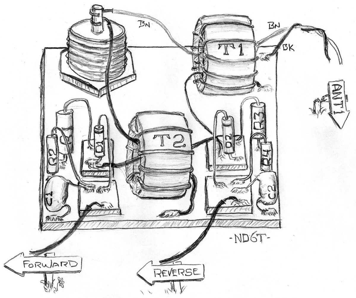

Don’s drawing is so good, I just couldn’t resist posting it here. It is part of an article he did for the BITXHACKS blog describing how to add a Stockton bridge forward/reverse power meter circuit to your rig. Check it out:
http://bitxhacks.blogspot.com/2017/03/nd6ts-forward-and-reverse-power-meter.html
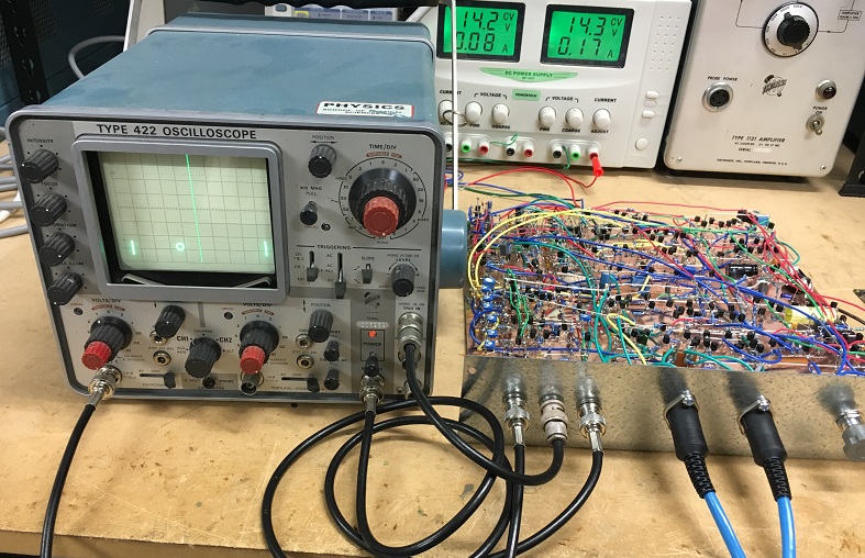
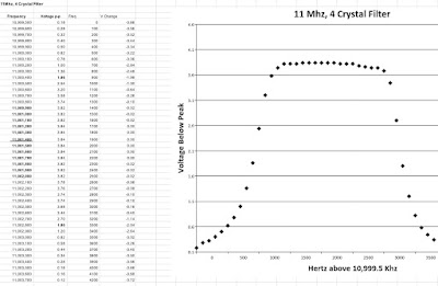
N7SUR’s Nice SSB Filter — Nail Polish Stuff Adds Soul to the New Machine
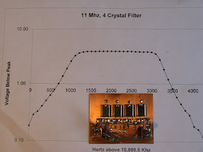
That’s a beautiful graph, don’t you think? In addition to the very pleasing results, I liked Bob’s methods: the “by hand” collection of the data points using an AD9850, a ‘scope and a notepad (see below); the filing down of ceramic disc caps; the use of nail polish hardener — all this adds a definite artisanal element to this project and puts more soul in the new machine.
Like Bob, I too kind of bailed out on the Q calculation when I was doing this. But as I recall there is a variation on the G3UUR method that yields this parameter too, right?
Bill:
I’m reluctant to share this with you because the results appear too
good. I’ve attached a graph showing my four crystal, 11Mhz
filter measurements. The graphed points are read values using my
AD9850 DDS VFO feeding to a TEK scope.
A TIA amp was used for input and output of the filter. My development software was the Steder-Hardcastle software as presented in November 2009, QEX.
I am now practiced in the black art of filing off the tops of disc
ceramic caps to “adjust” their values. This black art also involves
the mysterious qualities of Sally Hansen Nail Hardener.
Let me share my method for developing the filter.
I’ve built CW filters before but this was my first effort at SSB
bandwidth which is less forgiving.
The G3UUR oscillator method (see page 3.19 in EMRFD) is a simple and
effective filter design method. but it does not provide a measure for
crystal Q, a value which impacts filter insertion loss.
So I decided to choose crystals with proven pedigree. These were 11 Mhz crystals from Mouser, part number 20-HCA1100-S. A lot of ten costs $5. These were the crystals selected by Jim Kortge, K8IQY, for use in his 2N2/20 rig.
For software, I use the Dishal package that can be downloaded from the ARRL and other sources. This package was the basis for the
Steder-Hardcastle article in November 2009, QEX. The “Xtal” pull down
menu provides entries for an individual G3UUR oscillator.
Simply put, all critical filter input values are generated by reading
the change in crystal frequency as an additional capacitor is added
into the oscillator circuit.
I suggest starting with a 4 crystal filter. Only two capacitor values
were required for my filter. Five capacitors were required–two series
and three shunt.
Start by reading the “open switch” frequency for each crystal. Sort
the crystals into increasing frequency order and choose the four with
the most narrow frequency span.
Using the pull down menu measure the individual crystal measures for
Lm, Cm, and series frequency. Average these across the four crystals.
The Lm or Cm and series frequency are placed into the Dishal software
main menu. Also enter the average Cp which is the measured capacitance across the crystal leads.
Finish up the main menu entries by entering the number of crystals (4), and the desired bandwidth–generally 2.4 to 2.9 Khz. Finally enter the acceptable ripple, which is often 0.1db.
Let the software calculate the filter values. Expect some odd
capacitance values. By changing the filter bandwidth–say from 2.4 Khz to 2.35 Khz I can move one of the capacitance values to a standard value.
The software also displays the input and output impedance. If the
filter is centered between two TIA amps, this filter impedance must be
transformed to 50 ohms in the amps. This provides the transformer
winding ratios.
The Dishal software has always given me good results. But I haven’t
compared its results to Ladpac–especially GPLA.
Bob -N7SUR
Pete’s 60 Meter DifX
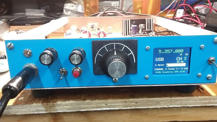
Oh man, run — don’t walk — to the N6QW blog and check out Pete’s amazing 60 meter DIFX transceiver. DifX is another N6QW contribution to the lexicon: it refers to a transceiver that has an architecture DifFERENT from that of our beloved BITXs. Pete means no disrespect to the BITX — he just sees the value in sometimes doing something different. I understand this completely — I myself am on my FIFTH BITX (three scratch-built and two modules) and definitely felt the need to do something different. (That’s why I built the OLED NE602 rig.)
Once again Pete Juliano shows himself to be a man ahead of his time: Anticipating FCC approval of a VFO tune-able segment in the band, Pete has made Channel 3 on his rig tunable with a rotary encoder. Hopefully, we will all soon need this. Pete is already there. FB OM.
My reaction to 60 meters has been very similar to Pete’s. We will talk about this on the next podcast (this Saturday).
Pete’s blog has a great description of the new rig, complete with a really nice video. Check it out:
http://n6qw.blogspot.com/2017/03/a-new-line-of-transceivers-difx_23.html
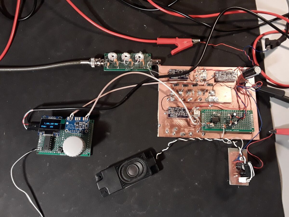
A Slovakian Al-Fresco Digi-Tia Homebrewed In France (and an improved AD9850 VFO)

Hello Bill and Pete,
Thanks for the podcast! My normal occupation is more computers and
software but your podcast got me motivated to melt some solder. So I
want to share a bit of what has been cooking on my bench.
I used to have a Yaesu FT-450 but sold it – I am living in a tiny rental
apartment in France without any place where to put a proper antenna so
it was only collecting dust. And where is the fun in operating a
factory-made rig, right?
So I have been working on this instead:
http://janoc.rd-h.com/archives/541
This “al fresco” rig is “half-DigiTIA”. Half because there is no
transmitter part (I don’t have a French license and I am too lazy to do
the paperwork and convert my Slovak one). The purple modules are TIAs,
as designed by Wes Hayward, using 3x 2n3904s, only built using SMD
components to keep them small and tidy.
VFO & BFO are Si5351 + ATMega328, with an OLED module and code adapted
from Pete N6QW. It uses 11.997450 MHz IF because that’s where most of my
12MHz crystals actually matched.
The 40m bandpass filter is taken verbatim from the BitX 40 design – I
have only changed the coils to use toroids instead.
For audio I have used LM386 with a NE5532 opamp as a low noise preamp
because the audio was a bit low. The TIAs don’t have a lot of gain and I
have only an indoor magnetic loop for antenna so had to compensate for it.
I have another, a bit older project that became quite popular – firmware
for the AD9850 DDS VFOs using an Arduino and a character LCD. It is a
much improved replacement for the one from Richard, AD7C.
http://janoc.rd-h.com/archives/502
Perhaps it could be useful to someone.
Keep up the good work and 73!
Jan OM2ATC (at the moment “in exile” in France)

An Si5351 Ham Sandwich from China (with video)
Ernesto Marquez alerted me to the offerings of CRKITS — Chinese Radio Kits:
http://crkits.com/ Their Si5351-Arduino Pro Mini “sandwich” is quite interesting. Here is a video on the device:
I must say, that nice little sandwich seems to be crying out for an organic slice of OLED…. How about it Adam?
While there is, of course, an enormous amount of electronics coming out of China, I haven’t seen much that comes from actual Chinese radio amateurs. But CRKITS is the work of a real Chinese ham. Adam Rong (Rong Xinhua) BD6CR seems like a very interesting fellow. From qsl.net:
About BD6CR/4
Adam Rong (Chinese name: Rong Xinhua), BD6CR/4 was first licensed in 1996 while in university in Hefei, Anhui province and now holds Class 2 Chinese amateur radio license (FCC Amateur General license equivalent). After graduation from university, he moved to Shanghai and call sign changed to BD6CR/4 in July 2003. Adam is now living in Pudong new district with his XYL and their son.
Adam holds a Master of Engineering degree in computer architecture and is an Engineering Program Manager in computer hardware industry. In spare time, Adam has written a lot about ham radio for magazines and papers, mainly about QRP, homebrew projects, APRS (Automatic Packet / Position Reporting System) and ham radio software applications. Adam has also translated two ARRL’s books into Chinese for Post and Telecom Press in China, including part of the ARRL Handbook and ARRL’s Low Power Communication: The Art and Science of QRP by Rich Arland, K7SZ.
You can contact Adam by email, or track Adam’s real time position on Google map by clicking this link.
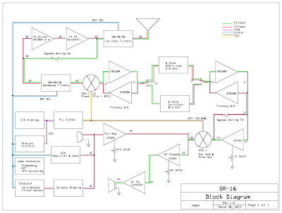
N8NM’s SR-16 Hallicrafters Tribute RIg
Bill, Pete:
The rig is loosely based on the Hallicrafters SR-160 transceiver, since I’m using a RD16HHF1 in the final RF, I’m calling it the SR-16. It’s a tri-band rig covering 80, 40 and 20m. Architectually, it’s similar to Pete’s JBOM, which is partially coincidental (thanks for sharing the article, Pete!) The heart of the rig is the W7ZOI hybrid-cascode IF, a really slick circuit that really makes the rig a joy to use.
Frequency generation is handled by the ubiquitous Arduino/Si5351 combo and a sketch based on Tom, AK2B’s “Multi Function VFO”, to which I added functions for selecting the appropriate bandpass and IF filters, generating CW, RIT, and dual VFOs (with split functionality), the state of which is saved in EEPROM when the rig is powered-down.
The rig’s just about finished – I’ve got the remaining parts ordered and hope to have it on-the-air soon.
73! – Steve N8NM
DARK SIDE TO THE MAX: WA7HRG’s Android Tablet SDR (with a question)
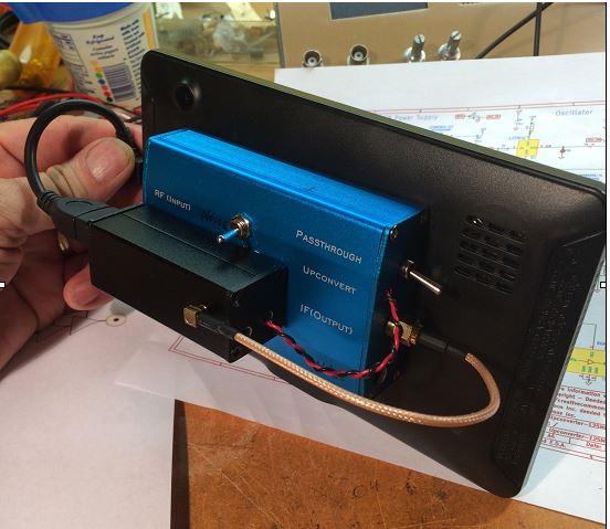
Jim’s experience with the Android tablet SDR was very similar to mine. But he used a “Ham It Up” up converter ahead of the RTL-SDR while I used an RTL-SDR modified for direct sampling of HF. I built a pre-amp/pre-selector stage for mine. On my Android Tablet (50 bucks via Amazon) I found the touch screen to be kind of clunky — it was hard to get the receive passband lined up with the incoming signal. The touch screen was not nearly as smooth as the one on my IPhone. A Bluetooth mouse solved that problem.
Like Jim, I am using SDRtouch from the GooglePlay. I’ll have to follow his lead and try Droid RTTY and PSK.
My reaction to the completed project was also similar to Jim’s: He writes that this is, “The first and last of my SDR adventures. This is just not the same as scratch building!” Indeed, it is not. But still, for very little money you end up with a pretty impressive receive capability, and you get some valuable insight into an intriguing method of receiving radio signals. And you don’t have to mess with Linux!
I have a question for the SDR gurus: With direct sampling, we are just running an ADC at RF. So we no longer need an I-Q front end to take care of the image problem we had when we were running soundcard-based SDRs, right? But I sometimes I hear that even with direct sampling systems, there is a digital generation of I and Q signals. Why would you need I and Q if you are just digitizing the incoming passband, multiplexing it, and sending it to the software?
Hi Guys
OK, so I am a little (A LOT) behind you guys in my bench work. Several unfinished projects are waiting in the wings. But I thought I would also dabble in Software Defines Radios. Thought I would go the Raspberry Pi route as Pete did. Then I woke up and sided with Bill. I don’t want to learn Linux!!
For about the same price as a Pi-3 and a 7” screen I bought one of Bills Android tablets and I found on eBay an estate sale that had a bag of NuElec parts. The RTL dongle, a Ham it Up vs. 3, and several cables, all unused. Last but not least I bought an Android ‘On the Go’ USB cable adapter.
I removed the LED and UV diode for the remote to drop the current some. Then tapped some power off the USB connector and ran it out to the Ham it Up. A few holes and some double sided carpet tape and ‘Bobs Your Uncle”. I added an enable switch to the up converter for the noise source but still waiting for the SMA connector to come in. Then I’ll see what that can do as a poor man’s spectrum analyzer for filter design.
I found several interesting apps on GooglePlay. Besides the SDRTouch program I downloaded Droid PSK and RTTY. Also the RFCorb client that allows you to connect to hundreds of remote stations around the world. That I may have to spend some time exploring but not really part of this build.
The Up Converter fired right up and after tuning around some I jumped to 14.070, the PSK hot spot. The tablet truly does multitask. I left SDRTouch running and opened Droid PSK. A waterfall full of signals jumped up and I was easily copying stations on the East coast and Canada.
All this running on the USB power from the tablet! How cool is that. After about 45 minutes or so the battery was about half. The only problem that I may have to address is that the tablet and/or the Ham it Up gets pretty warm and my carpet tape lets go and things fall apart. HA. Haven’t ran it long enough yet to see what else the heat might effect.
So that was fun and I will be playing with it some more. I have coffee on Mondays with some ham buddy’s. When I showed them the PopCorn radio they jibbed about it not being battery powered.
Well Monday is coming!! HA
Jim WA7HRG
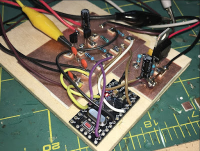
FB IBEW HB DC CW de UAE: A65DC’s International Homebrew Rig

Good evening!
After my JOO moment, Bill put me in contact with Pete Eaton, who suggested that I would have a look at the schematics for K4GC 40m CW Transceiver.
And I did, It was just perfect for me, low part count, lots of things done in software!!! Perfect Bryan!
I started off the build and both Bryan and Pete supported me along the way, thank you!
So here we have it:

The design slowly deviated further and further from the original, but I think I learned quite a lot by starting to make it “my own”.
The Arduino was changed to an UNO, yeah they are clunky and big, but I was not shooting for a pocket-size anyway… and they do have a proper USB port.
The RF-path is now switched by a relay straight after the filter, when the relay is relaxed the antenna is connected to the mixer, when I touch a paddle it connects to the TX circuit.
I have a short hang time from the last key input and it goes back to RX, VOX Delay I guess.
I completed the 700Hz bandpass filter, boy! this makes it a much nicer rig to work CW, I originally I skipped this filter for no good reason? That is the board standing up in the picture.

The TX circuit is a two stage, the first stage is a replica of VK3YE beach40 amplifier circuit, that also uses DB139. The second stage is a spin of the EMRFD Page 2.38 IRF511 Amp.
I have cranked it up to 17w, but it gets too hot too fast, as you can see I don’t have any proper cooling yet, I need to redo this board and plan for the heatsink a bit better.. it is now set around 10w, still getting hot, “599 TU 73”.
To be honest my CW does not go much further anyway, but I guess with this radio now completed I have one more reason to get my speed up.
I use for convenience both CLK0 and CLK1, when I go into TX I switch off CLK0 and do the keying on CLK1, both transmitter stages are powered up the whole time (until I stop keying as described above)
As the 700Hz filter worked so superb, I decided that I wanted to introduce “modes” to the rig, I can now switch the audio either thru the filters (CW) or straight to the AF amp (AM).
I do enjoy listening around, and we have a lot of AM stations on offer in my region.
I kept the smart RX mute transistor circuit and when I ask the Arduino to change mode, it will mute the receiver quickly, pull the relay and then un-mute again, no ear pain from the loud relay click. (I am happy with that detail).

The 2 line display became a four line, and I can change Tuning Rate, RIT, Key Speed and Mode by using only the encoder and the one button built into the encoder.
The front panel sports, on off, Headphones, Paddle and volume, the display and the big knob.
Power connector and USB Port on the side. I did complete the CAT control changes while working on this radio, it now uses the classic Kenwood interface e.g. TS480. (A lot fewer questions from the PC to answer.)
The CAT control works very nice while using N1MM, it works a lot less nice using CQRLog, I guess it has to do with the number of times the software in the PC is asking about things from the radio.
I will look into logic to only worry about incoming serial requests if I have not answered for some time, and never answer while in TX…
By pressing the VFO button a small arrow appears next to TR, if I push again it moves the arrow down to RIT and so on.
if I turn the knob with the arrow standing in front of e.g. KEY it will increase or decrease the KEY speed, when I press again, it will return to frequency control.
Oh, another detail (that I am happy with) while the arrow is in front of the KEY, you can fiddle with the paddle with out transmitting.. practical for testing the speed.
So this is a K4GC transceiver with bits and pieces from VK3YE and bits from the A65DC laboratory in Dubai, truly international.
To trim things in I scheduled a QSO with a local ham here, and things worked very nice, later the same night I made my first “DX” contact with RM2D!!! Moscow!!
What are the odds that a Swedish guy living in the UAE makes the first contact to another Swedish ham who lives in Russia!
73,
Martin A65DC
Homebrew Canoe (video) (beautiful)
I post this because it is nice to occasionally look up from our soldering irons and take a look at what other people are building. This video is really beautiful.
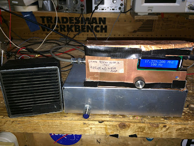
Channelized! BITX 60 with the Five Channels (with video)
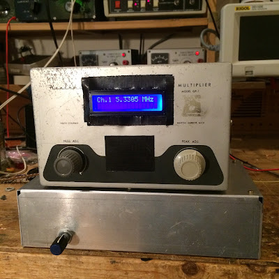
Here’s an update on my BITX 60 project. The modified module is in the lower box. An Arduino Uno and an Si5351 (this one with unreleased smoke) is in the Heath QF-1 box on the top. I am using an Arduino sketch written by Don ND6T. It spits out the needed 17 MHz LO freq needed for each of the five 60 meter channels. You can scroll through the channels by just holding down the rotary switch interrupt button.
There is a move afoot to liberate from channelization about 15 kHz of the 60 meter band. When that happens, I’m ready to go — I’ll just reconnect the rotary encoder for the Si5351 and load some new code. I suspect that by the time that happens, Don will have modified his code so that the 15kHz “tunable” segment will be integrated into the current program and will appear as one of the options as you scroll through the choices.
For reasons that most readers will understand, I have resisted channelization for many years. But here I am, channelized on 60. It is not so bad. I’m having fun listening to a new band, using a modified BITX, an Arduino, a bit of Heathkit and code from a fellow ham.
BITX 60 (with three short videos)
Inspired by Don ND6T, I decided to put a BITX40 Module on the 60 Meter band. All you really have to do is modify the bandpass filter. Don showed us how to do this by simply adding three 100pf caps. I was going to order SMD caps, but this just didn’t seem right — I found three of the old “with wires” kind and easily soldered them into position. The bandpass shifted as Don had promised.
You also have to change the VFO freq. You need it to be in the 17.3 MHz range. Don has a nifty program for the Raduino that also works with the Si5351/Ardunio Uno combo that I use. It keeps you on the five channels currently authorized on 60. Unfortunately I managed to let the smoke out of yet another innocent Si5351 breakout board. Amazon and Lady Ada are sending me another one, but in the meantime I pressed into service an old AD9850 DDS. I had a little trouble getting the 17MHz signal through the BITX’s VFO 4 MHz VFO system, but I eventually figured it out. (More on this later.)
The receiver is working nicely. I like the relaxed 60 meter conversations.