For now, I’ve put the Moxon project on the back burner. I will take it up again once Old Sol starts showing some spots. In its place a 135 foot doublet is going up. I got at a hamfest a while back. (It is the only HF antenna that I ever bought!) It is the SPI-RO Manufacturing Company’s Model A-10. It came with 100 feet of 450 ohm window line. It will be up on the roof soon.
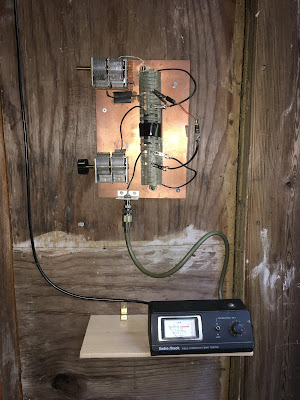
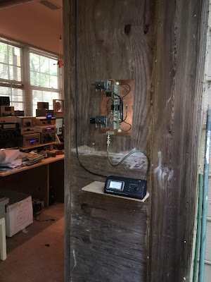
Today I put the tuner on the wall in the car port right outside the shack. I even built a little shelf for the SWR meter (used one of those Whole Food grilling planks!). I put a 25 ohm resistor where the feed line will connect. I was able to tune it up on the two bands I tried: 40 and 17.
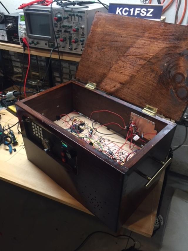
There is a smaller coil inside the big one — the smaller coil resonates with the lower variable cap.
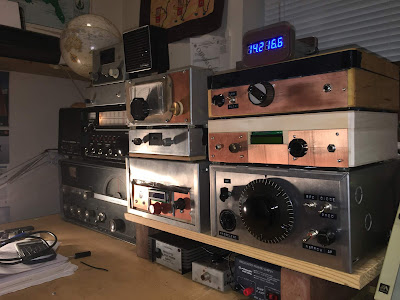
You can see all the homebrew rigs in the background — waiting patiently for the antenna.
I actually built the tuner back in 2012, but never used it. Description here:
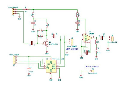
I will try to provide a schematic and more details soon.