Bill,
Just listened to the latest SolderSmoke podcast where you asked why is it that an RF amplifier may be required on the higher bands but not on 40m and 80m for example.
At high frequencies the atmospheric and ionospheric noise levels are lower, so if noise figure of the receiver is reduced it will improve the signal to noise ratio you get from the receiver. Adding gain -after- the mixer will not improve the noise figure of the receiver as it will be limited by the noise figure of the mixer. You need an RF amplifier which will itself have a lower noise figure than a mixer (certainly a passive mixer), to lower the total noise figure of the receiver to take advantage of the lower effective antenna noise temperature at higher frequencies.
This becomes very important at VHF and above, where antenna noise levels are much lower than at HF.
So, it isn’t so much the overall gain of the receiver that is important with weak signal work, but the overall receiver noise figure which is determined to the largest degree by the first stage of the receiver.
There are spreadsheets available that will easily calculate the noise figure of cascaded receiver stages knowing the individual stage gains and noise figures.
One also has to be careful with the gain distribution throughout a receiver, if you have too much gain early on in an effort to improve the noise figure overall, you may overload the subsequent stages producing IMD with multiple strong signals. So there is a compromise to be met between noise figure and strong signal performance.
Going back to VHF and above if you have an antenna fed by coax with some appreciable loss then improving the receiver RF stage noise figure is not the best way to go because you are amplifying the signal after the loss the of the coax. What you need to do in those circumstances is to use a low noise masthead RF preamplifier which will give you gain and establish the noise figure of the receiver before the loss of the coax. Again there are spreadsheets to help with these calculations.
At VHF where an antenna is pointed at the horizon, the antenna sees the noise from the ground on the noise from the sky. As we elevate an antenna for EME or satellite working, then the effect of the ground noise should reduce (there will always be some due to side lobes) and then the receiver can benefit from even lower noise figure as the effective antenna noise temperature is now mostly determined by sky noise which at UHF is much lower than ground noise.
These last two days I have been able to see and hear the sun noise on my 2m receiver as the sun set on my single 10 element yagi pointed at the horizon. Using WSJT’s noise level scale I could see it measure 12dB noise level and then once the sun set it dropped back to about 3dB noise indicated, most of that being local QRN from an antenna sidelobe from my neighbour’s house and his electronic devices which put out quite a bit of wideband noise on the band. (about 8dB above the lowest background level I can normally detect).
To summarise, at LF where noise is high you don’t gain anything by having a low noise figure receiver, and you actually lose out if you have too much gain early on as it will degrade strong signal handling.
At HF as manmade, atmospheric and galactic noise levels are lower, you can benefit from lower receiver noise figure and the way to lower your noise figure is to use lower noise amplifiers in the early stages of the receiver. Adding gain in later stages does not reduce the noise figure overall as the noise figure is largely determined by the first stage or stages.
At VHF using even lower noise figure devices in the RF stage will improve signal to noise.
Here is a practical test you can carry out. Switch between a dummy load and your antenna. If the background noise level increases when you switch to the antenna, then your receiver is sensitive enough, lower noise figure in the receiver isn’t going to help. If it doesn’t increase then you have scope for improving the sensitivity of the receiver by reducing the noise figure of the receiver as you are no longer limited by antenna noise.
Incidentally it is good to have a preamplifier that can be switched in an out of circuit so that you can reduce the noise figure when conditions allow ( low noise atmospheric noise levels for example), but switch it out if noise levels are high and signals are strong so that receiver overload and IMD don’t occur. You can do something similar with an input attenuator to reduce strong signals where necessary.
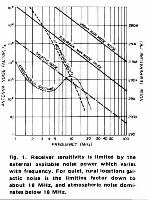
I don’t have a link here to the graph of manmade, atmospheric and cosmic noise levels versus frequency, but once you see one it becomes obvious why low noise figure receivers are not required at LF and MF generally.
73 from David GM4JJJ
Bill,
I found the article with graph of noise v frequency at last, in Ham Radio Magazine 1975!
A good read and as valid today as then.
I don’t have a link here to the graph of manmade, atmospheric and cosmic noise levels versus frequency, but once you see one it becomes obvious why low noise figure receivers are not required at LF and MF generally.
73 from David GM4JJJ