
http://hackaday.com/2016/11/09/resurrection-pressing-ww2-radio-equipment-back-into-service/
Author: Peter Marks
SolderSmoke Podcast #191 RIGS! REAL RIGS!, BITX40 Module, EMRFD, MAILBAG

SolderSmoke Podcast #191 is available:
http://soldersmoke.com/soldersmoke191.mp3
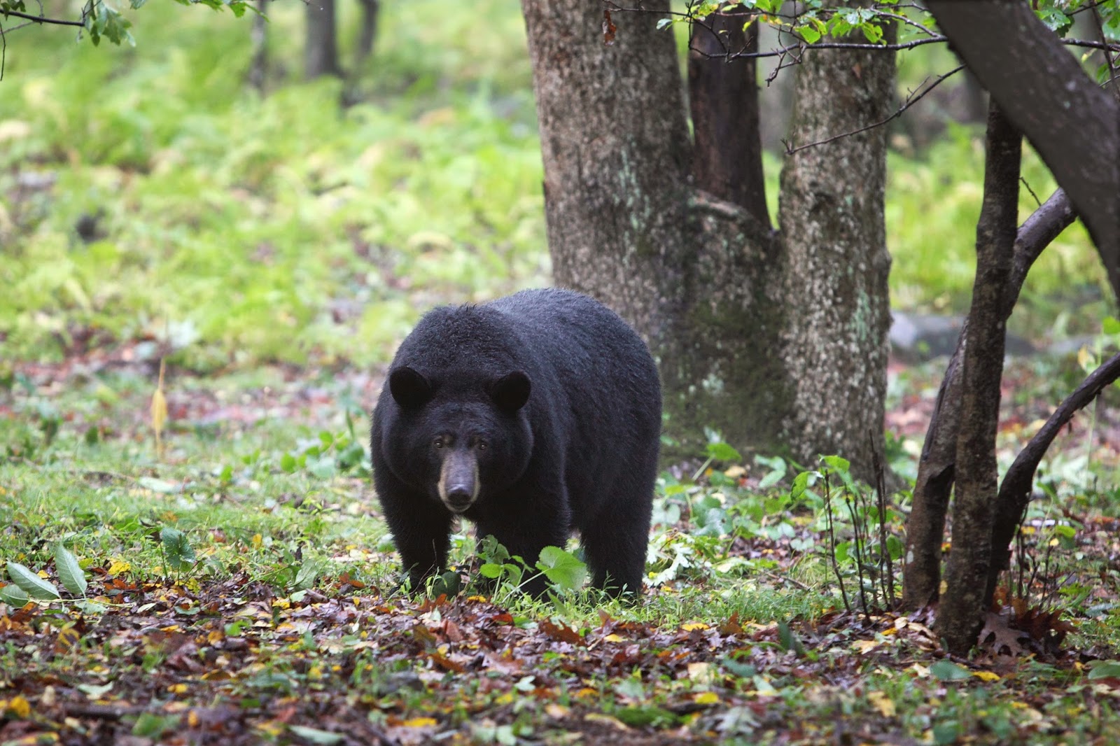
TRAVELOGUE AND FAMILY DOINGS: Pete son’s wedding, Billy’s Birthday, Gonzalo safely home in the Dominican Republic, MORE BEARS IN THE SHENANDOAH WOODS
BIG NEWS: EMRFD LIVES ON! Three cheers for Wes and for Tom Gallagher of the ARRL.
BENCH REPORTS:
PETE: FPM Rig. Some Halli history. A TRUE RIG! Working Japan.
WITH 600 WATT LINEAR AMPLIFIER!!!!!!!!!!!!!!!!!!!!!
New FEELTECH Sig Gen.
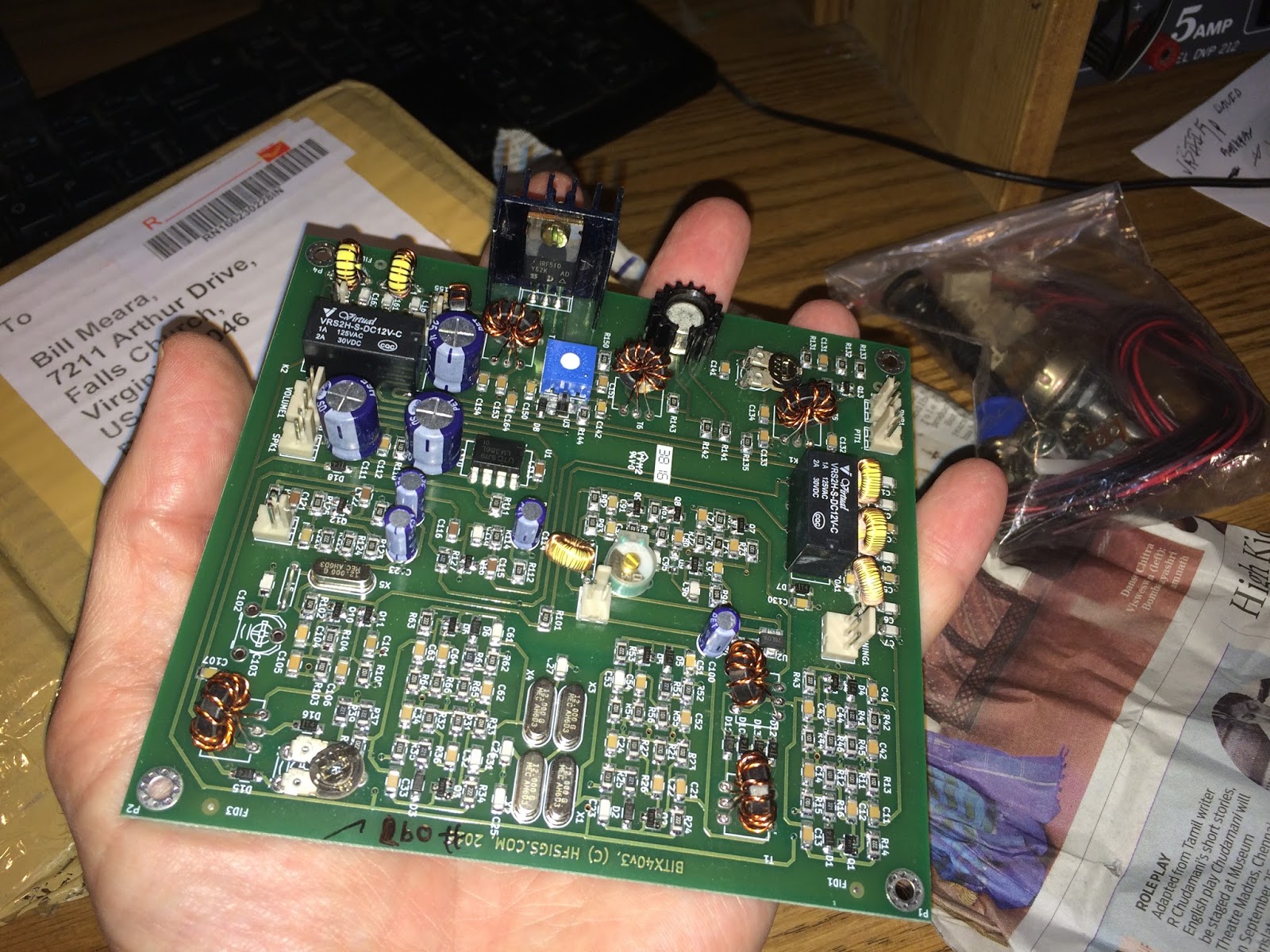
BILL: Farhan’s BITX Module
Built to Mod, built to get you started in homebrew
Very impressive. BITX in miniature. But completely recognizable.
REMARKABLY stable.
Farhan personally checking each one.
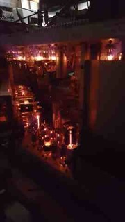
Ladies collective doing toroids. DONATION money bought them some Diwali candies!
VFO Drift: Will NP0 SMD caps and lower current help enough?
My Analog VFO — BANDSWEEP
QRPppppppppppp with REX’s Hamfest Buddy. Thanks Rex and Bob Crane.
HB2HB with KW4KD
MAILBAG
Jan’s Netherland Mate Mighty Midget
Charlie’s Kiwi DSB
Steve, Donald Fagan, and Jean Shepherd
Rob VK5RC repairs Tek Tube ‘scopes
Colin M1BUU Si5351 superhet
Denis Klipa and NRL 3538
Jonathan M0JGH Wizard of Wimbledon Matchbox rig
JH8SST Simpleceiver
Peter Parker Vk3YE Reviews Book
Peter GW4ZUA Welsh LBS
Michael Rainey helping hobbyist in Germany with tuning forks.


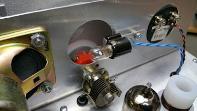
Reverse Polarity Protection
When I opened the package from India and saw Farhan’s s beautiful board with all those little SMD parts, I immediately worried about frying those parts by accidentally reversing the polarity of the 12 volt DC input. Believe me, this can happen. It is especially likely during the early, enthusiastic testing and experimenting that takes place in the days after the arrival of a new rig. So, my friends: Save yourselves the agony of fried components! Don’t let your BITX 40 Module go up in smoke! Install a simple reverse polarity protection circuit BEFORE you start working with your new board.
Here is what I did: I just took a diode (a fairly hefty diode) and I soldered it in between the pins of that neat little circular power jack that Farhan sent with the module. Be sure to solder it in so that it does NOT conduct if you have connected the power correctly. The arrow should be pointing to positive terminal. Then put a fuse (3 amp or even a 2 amp) in the line from the connector to the power supply or battery. If you don’t have a holder you can try just soldering the fuse into the line.
With these two little parts, you can save yourself a lot of grief: If (WHEN!) you connect red to black and black to red, that diode will conduct like crazy and will blow the fuse. You’ll just have to replace the fuse (and not the module).
On the Air with the BITX 40 Module
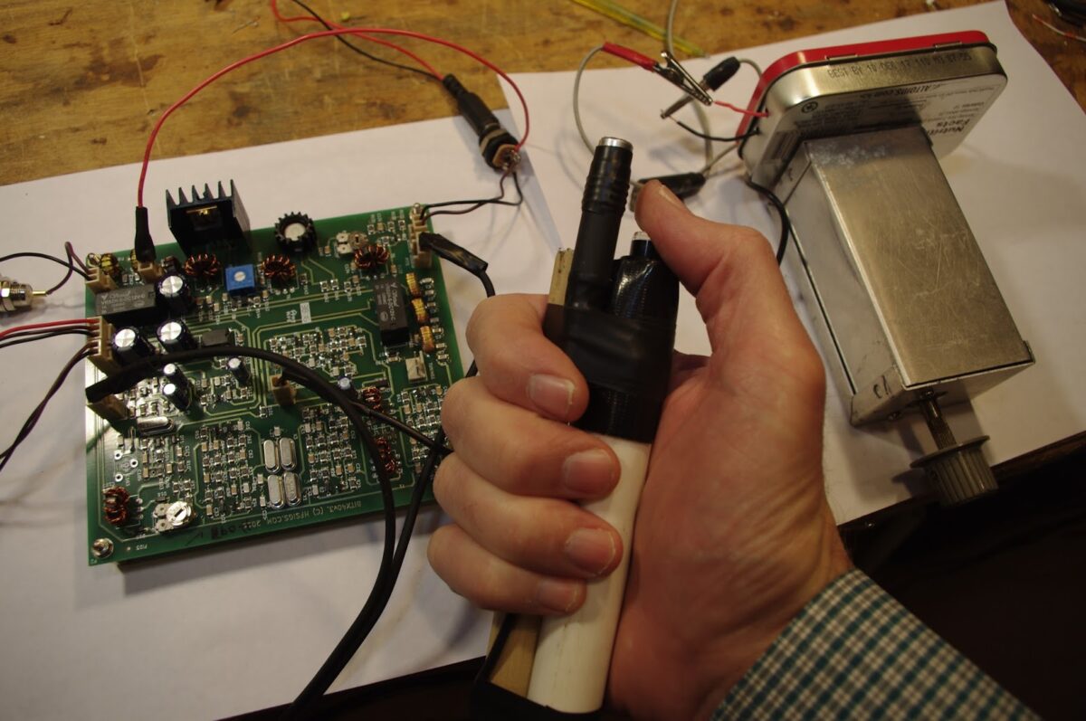

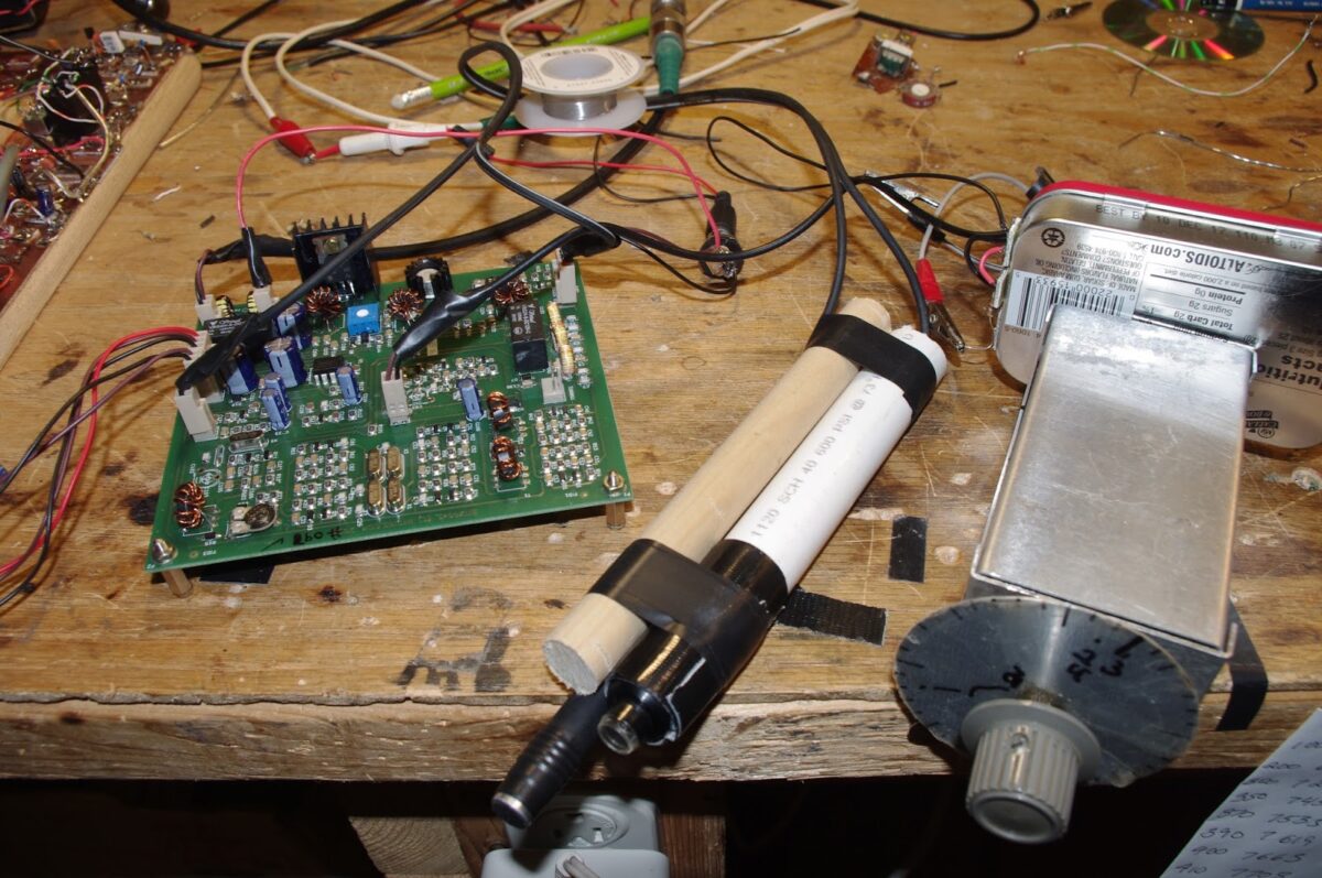
This morning I built a mic/PTT for the BITX 40. I used the little electret element that Farhan sent with the rig. The element sits atop the plastic tube from a pen. For the push-to-talk I used a little push switch that locks down (on) until you push it again (which opens it). This is very convenient — you don’t wear your thumb muscles out on long “old buzzard” transmissions! I used some PVC pipe and some wooden dowel to make the thing a bit ergonomic. It is held together with Gorilla tape.
It works great! I put the rig on the air this morning and very quickly worked KD3TB up in Pennsylvania — Irwin was testing his K3. Then I worked KM4LWP — James was only a mile or so from me, running 3 watts from a KX3. Then Mario, K2ZGW called in. Everyone said the rig sounds great.
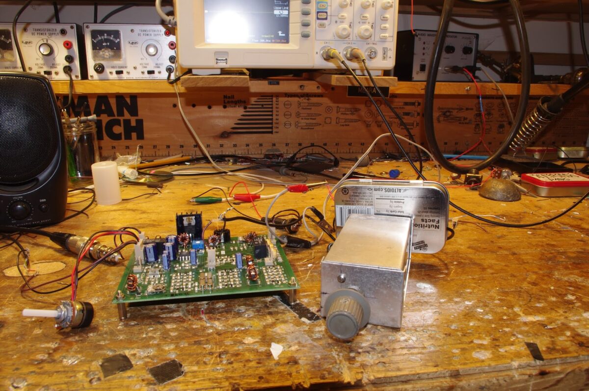
In the picture above you see the rig, the mic and (on the right) the VFO.
On the Air with the BITX 40 Module
This morning I built a mic/PTT for the BITX 40. I used the little electret element that Farhan sent with the rig. The element sits atop the plastic tube from a pen. For the push-to-talk I used a little push switch that locks down (on) until you push it again (which opens it). This is very convenient — you don’t wear your thumb muscles out on long “old buzzard” transmissions! I used some PVC pipe and some wooden dowel to make the thing a bit ergonomic. It is held together with Gorilla tape.
It works great! I put the rig on the air this morning and very quickly worked KD3TB up in Pennsylvania — Irwin was testing his K3. Then I worked KM4LWP — James was only a mile or so from me, running 3 watts from a KX3. Then Mario, K2ZGW called in. Everyone said the rig sounds great.
In the picture above you see the rig, the mic and (on the right) the VFO.
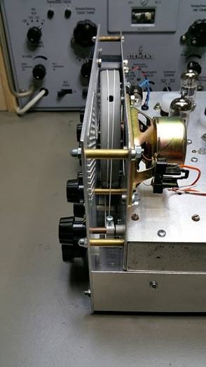
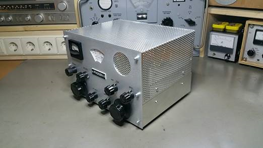
It’s Ugly, But It Gets You There: Pete’s Latest Rig
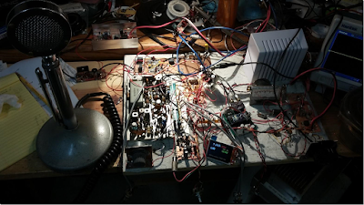
That, my friends is an extreme example of what we mean when we use the word “rig.” This magnificent machine sent Pete’s melodious voice across the mighty Pacific several times during the recent CQ WW contest.
Pete wrote to Jun:
Hi Jun,
This weekend is the CQ World Wide SSB contest and I just worked three JA stations on 40 Meters. The time 1400 UTC. I must confess that I was using 600 watts to my droopy dipole but they came back on the first call. So there are paths open and perhaps 600 watts was overkill but the timing seems like it works for a good path to the west coast. Along the way I also worked a station in Hawaii (KH6).
See if you can find some 813 tubes as they make a great grounded grid linear amplifier tube and a pair will give you 600 watts. see http://www.ohio.edu/people/
The rig I was using is shown below. The mainboard came from a Hallicrafters FPM 300 (late 1960) to which I added the Rx Tx Mixer (SBL-1), my stock 2N3904 bi-directional amp board, the 2N2222 + BD139 driver stage using the EMRFD circuit and a 2SC2075 final which gives about 3 watts. This in turn drives an intermediate SS amp to 100 watts and then the SB200 to 600 watts. The FPM 300 used a 9.0 MHz IF frequency.
Of course no rig today from N6QW would be complete without a Si5351 and the color TFT display. Rounding this out is an LM386 audio amp stage. Cosmetically the rig doesn’t look pretty but sure works well.
73’s
Pete N6QW
(The comments about the 813s are kind of SHOCKING, coming from a member of the QRP Hall of Fame!)
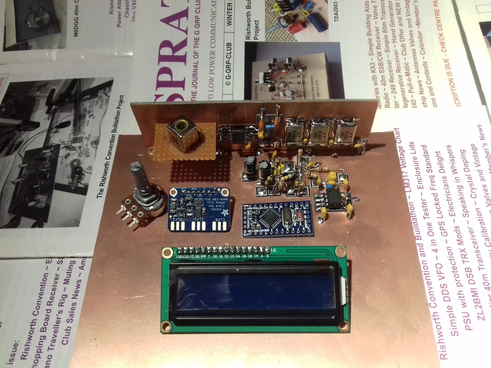
Hacking the Hackable BITX 40 Module: VFO is the Way to Go!

I am having a lot of fun with Farhan’s new BITX 40 Module. I think I’m doing exactly what Farhan intended people to do with this rig: work on it, modify it, improve it.
I’ve been working on frequency stability. I was, I admit, skeptical from the start about the stability of a thumb-sized, SMD, varactor-tuned VFO with a ferrite or iron powder toroidal coil. Don’t get me wrong — it worked. But it drifted. It seems to me that it would be asking too much to expect a VFO like this to be drift-free. (But I may be wrong — are there any SMD, varactor-tuned VFOs out there that DON’T drift?)
First I thought it might be the 9 uH metallic core toroid. So I replaced that with a 10uH choke — no ferrite or iron powder in there. That seemed to help a bit, but SSB QSOs would still quickly drift into Donald Duck chatter. Then I thought it might be the varactor diode. I let it warm up. A lot. Still, it drifted. Then I thought it might be the trimmer cap, so I took it off the board. No change. During this process I noticed that even slight pressure on the board caused the rig to shift frequency. I began to suspect that the drift was just structural — a consequence of the physical characteristics of the SMD parts and the board. To get VFOs stable I’ve had to build them big: 10 X 10pf NP0 caps to make one 100 pf cap, large air-core coils, and big sturdy variable caps. I’d isolate the frequency determining elements in a box separate from the powered components. This little VFO just looked too small to be stable.
So faced with drift, at first I asked myself, “What would Pete do?” I took an AD9850/Arduino combination off the shelf and plugged the output into the “DDS” jack Farhan had placed on the board. I removed the 10uH choke. Viola! With the DDS tuned to 4.7 – 5 MHz, the receiver worked great. I briefly tried to updated the Arduino code to take into account the 12 MHz IF (so I could get an accurate frequency readout), but ran into the old painful Arduino IDE problems: Now it is claiming there are library problems. Not wanting to suffer through another round of digi-agony, I left well-enough alone. I used the DDS with the old code for one day.
But of course, I was not satisfied. Attaching a DDS or PLL synthesizer to the BITX 40 Module just didn’t seem right. Heck, it was kind of like just hooking up my FeelTech Chinese sig gen to the DDS jack. Farhan’s rig is simple, beautiful and ANALOG. The parts are small, but you can see them. You can put your scope probe on the collector of Q7 and see what is going on. DDS or PLL. It is a REAL HARDWARE-DEFINED RIG. So I decided to build a VFO. Pete calls VFO’s “grief machines” but for me, the grief machines are those little Arduino beasts. To each his own.
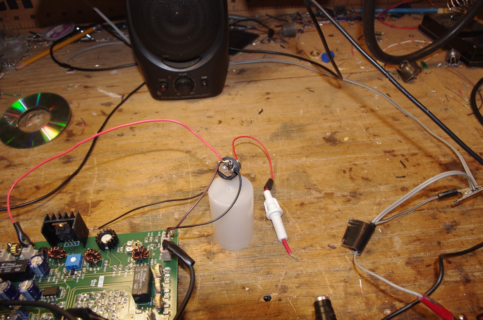
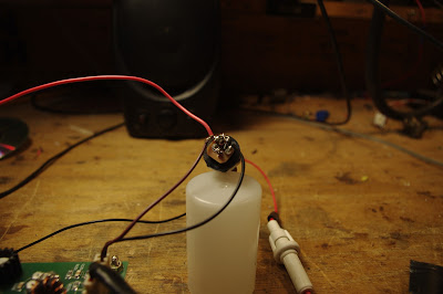
When I build a VFO, I start with the variable capacitor and the reduction drive. I found a nice one (with reduction drive) in my junk box. I tunes from 40 pf to 56 pf. I decided to use the super-simple Hartley circuit presented by Wes Hayward W7ZOI in SSDRA (page 34, fig 7).
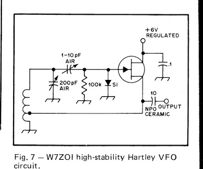
I went with a 4.4 uH air core coil (wound on a cardboard tube from a coat hanger). Consultation with on-line resonant frequency calculators showed that I’d need to put about 180 pf in parallel with the variable cap. For this, I used a bunch (maybe 10?) of small value NP0 caps in parallel. This really helps keep the VFO stable.
As I did with my HROish receiver, I put the coil and the caps in one box, with the MPF-102 and associated parts in an attached Altoids tin. Everything was glued and bolted down very solidly.
I only built the actual oscillator stage — I decided to use the buffer amps on Farhan’s board.
The oscillator started right up. I had to add and then take away some turns on the coil to get it to run in the desired range. Then I plugged it into the DDS jack — the receiver was working immediately.
I noticed, however, that it seemed a bit less sensitive than it had been with the AD9850 DDS. And when I grabbed the wire going into the DDS connector, audio output jumped dramatically. It took me a few minutes to figure that out: I think the output from my VFO was not adequately turning on the diodes in the diode ring. When I grabbed the wire, I was putting a lot of noise into the mixer port, probably turning the diodes more fully on (but also letting a lot of noise through).
Fixing this problem part was fun: Looking at the BITX 40 schematic, I saw that the two 1000pf feedback caps in the original oscillator were still in the circuit. I figured those caps would be sending a lot of my VFO energy to ground. So I fired up my hot air rework station and deftly removed C91, the 1000 pf cap that is connected to the base of Q9. Instantly the receiver started inhaling as it had with the DDS VFO. That was a very satisfying fix.
This whole VFO project was very satisfying. It was all done in one day, and all the parts came out of my junk box. I think I ended up with an LO frequency source that matches up in a pleasing way with the analog circuitry in Farhan’s rig. And here is bonus that I think is just what Farhan had in mind: this kind of circuit adds a definite homebrew element to the module rig.
I found that this external VFO improved stability significantly. I don’t know if it is as stable as the DDS, but with the external VFO the receiver no longer drifts away as I listen to SSB signals.
DONE! Jan’s AMAZING Mate for the Mighty Midget Receiver

Hi Bill,
Finally the Mate for the Mighty Midget is finished, just in time for the G-QRP Valve Day 12-13th of November.
Got the LO fixed for 40m by lowering the parallel capacitor from 150 pF to 100 pF.
Also the 68 pF series capacitor was lowered to 33 pF for some more band spread on 40m.
It now receives from about 7.0 to 7.4 MHz and from 3.45 to 4.0 MHz
Had to exchange C1 in the end, the one used initially quit every now and then.
I only had a large 3 section variable in the junk box covering 10-550 pF, which works fine now.
For the lower end of 80m I had to add additional 47 pF next to the 47 pF trimmer caps, so there it is about 600-650 pF max!
For the lower end of 80m I had to add additional 47 pF next to the 47 pF trimmer caps, so there it is about 600-650 pF max!
At the high end of 40, it is also just not too much.
The meter was used as a position indicator for C1.
Tried several ideas, but with no separate tube for AGC, I couldn’t get it to work as a S- meter
Read something about audio derived AGC, maybe this is worth a try.
The BFO can be switched off for AM reception.
Simultaneously the input on the mixer side of the crystals is disconnected but still coupled by some capacitance of the switch wires.
AM reception is possible, but not very good.
Need to find a better solution which doesn’t degrade the crystal filter properties to much.
(By the way, the detector regen. control ads about 4 dB to the AM sensitivity)
The receiver will mainly be used for CW/SSB reception, so maybe it stays this way for a while J
I hooked it up to the W1TS transmitter, which was very loud.
Didn’t foresee a T/R relay (learned a lot from this project 😉 ), so added this one between the front plates next to the RF and audio gain control.
The quit down everything a little, the RF gain pot is lifted of ground as suggested by James, N2EY at QRZ.com.
It helped a lot, but was still too loud if tuned exactly in the bandpass of the crystals.
The T/R relay now also switches an adjustable potentiometer at the input of the audio pre-amplifier.
The dial cord has no lag, and works very well for fine tuning.
Unfortunately the reduction drive went from 1:19 to 1:9…, the tuning capacitor only has a 180 deg. span.
Something to remember for the next receiver.
It’s a nice little receiver and quite stable after warm-up.
The only extra luxury a next receiver will have, is AGC.
But with no AGC it’s easier to tune the antenna tuner by ear J
There’s now a complete homebrew station here, antenna, feeder, tuner, receiver, transmitter, power supply, al home made J
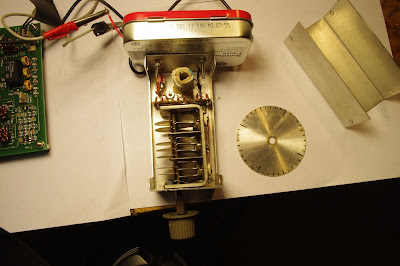
About the Mystery Hole….
If you haven’t guessed it by now, or Pete hasn’t told you, it is revealed in one of the pictures below.
I also made a little video:


Another Great DSB rig from New Zealand

So many great Double Sideband projects come from Down Under. There are the various versions of the famed ZL2BMI rig. And Peter Parker VK3YE has long been the acknowledged guru of DSB. In fact, Peter sent me an enthusiastic e-mail about the new ZL DSB rig pictured above — his e-mail arrived before the message (below) from the intrepid builder. I detect a bit of the “Tucker Tin” influence in this rig. (But perhaps this one is more Tupper than Tucker!) Charlie’s work has graced out blog posts before: http://soldersmoke.blogspot.com/search?q=zl2ctm
Be sure to check out his video: https://youtu.be/
Hi Bill.
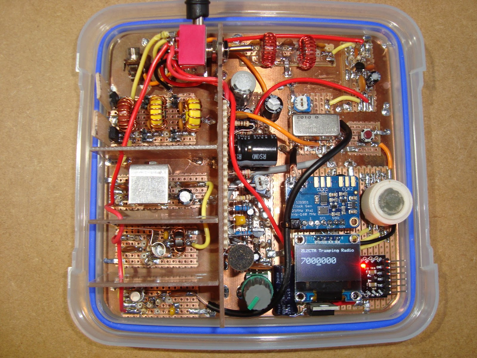
You asked recently on the podcast for listeners to let you know what they had on their work bench. Well I’ve been working on a tramping (hiking) radio, which is now complete. It’s a DSB 5W rig designed for 80, 40 and 20m, as well as our New Zealand mountain safety radio system. I designed everything in LTSpice as was suggested by Pete, N6QW. That was great, as I could ‘desolder’ components with the mouse and instantly see what impact it had on the output. An amazing tool that’s free! I highly recommend it.
Once again I’ve used upside down strip board for each stage, which are tacked down onto an un-etched copper board (earth plane). That seems to work really well for me.
The rig uses an Arduino mini driving a small OLED screen and a Si5351 DDS. The Si5351 is going straight into a SBL-1, which seems to work fine too. The AF strip is a 2N3904 before a LM386, which has enough drive to run a speaker. The TX amplifier is a three stage one with shielding between each stage. It’s made up of two 2N2222A stages followed by a BD139. That in turn is followed by three simple filters, one each for 80, 40 and 20m.
All-in-all it works really well. I’ve uploaded a quick video at https://youtu.be/
The next project will be a proper SSB rig using a crystal filter salvaged from an old Codan 7727. Like this one, it will use an Arduino and a Si5351.
Finally, I am certainly no expert in homebrew, but I hope my ‘dabbling’ will help inspire others to pick up the soldering iron and give it a go. If I can do it, then anybody can! There is certainly a great sense of achievement to operate a rig you built yourself.
Regards, and thanks to you and Pete for all your inspiration.
73’s
Charlie
ZL2CTM
I.G.Y., The Nightfly, Donald Fagen, Jean Shepherd and SolderSmoke
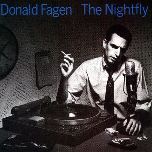
OK, so from time-to-time we talk about IGY, the International Geophysical Year. I was born during that scientifically momentous period. A lot of cool stuff happened. Amazing propagation conditions too. So for a while (around SolderSmoke 149) I was using the opening bars of Donald Fagen’s song I.G.Y. as the intro for the podcast. That song comes from Fagen’s album Nightfly. The album cover appears above.
This morning I got two e-mails from Steve N8NM about another connection between SolderSmoke and IGY. At first I thought he was pulling my leg. But before I show you the e-mails, let me show you another picture:
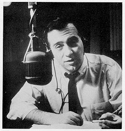
That’s Jean Shepherd. Can you dig it?
Steve writes:
Hey Bill!
I’m Listening to #149, where you introduced Donald Fagen’s “I.G.Y” as the new theme song. Have you heard that the protagonist on that album is based on none-other than Shep, K2ORS. Don’t know if that’s necessarily true, but the album title (The Nightfly), Fagen being from NY, and the era depicted certainly make that plausible…
I guess it’s factual – This is from an interview Fagen did with New York Magazine:
Your first solo album, The Nightfly, was inspired by fifties jazz disc jockeys. Which ones were your favorites?
Symphony Sid was very popular. Mort Fega was probably the best all-around jazz D.J. Ed Beach on WRVR would do this very scholarly afternoon show, and I’d listen to that when I came home from school. But the figure of the Nightfly was based more on a guy who didn’t play jazz records, Jean Shepherd. He was a monologist who used to just talk and tell stories and say funny things. He was a social satirist.
Symphony Sid was very popular. Mort Fega was probably the best all-around jazz D.J. Ed Beach on WRVR would do this very scholarly afternoon show, and I’d listen to that when I came home from school. But the figure of the Nightfly was based more on a guy who didn’t play jazz records, Jean Shepherd. He was a monologist who used to just talk and tell stories and say funny things. He was a social satirist.
Speaking of Shep: You’ve done him proud, not only in your HB radio efforts, but in proving yourself to be a very capable monologist for the several years between Mike’s passing and Pete’s arrival. Three Cheers for Bill! Give that man a brass figlagee with gold leaf palm!
73! Steve N8NM
By the authority vested in me by having once spoken to Jean Shepherd, I award Steve Murphy N8NM, the coveted Brass Figlagee with Gold Leaf Palm.
EXCELSIOR!
TRGHS
Farhan on What’s New in the BITX 40 Module
Writing to the BITX e-mail group, Farhan provides some very interesting information on the philosophy behind his new BITX 40 module, and on how it differs from earlier BITX designs:
The new builders are often caught in a catch-22 : to get on air they need to build a rig from scratch. but to build a rig, they need lots of experience. A way out was to provide working boards where we can get on air quickly, and then start improving and modding the circuit. this is the spirit behind the new boards. Consider them like you would consider a raspberry pi or an arduino : simple, working circuits around which you can grow your own radio.
In the new bitx boards, I have tried to keep as close to the original bitx as I could. however, there are a few departures that I thought the bitx builders here would like to know about.
i have to admit though, strangely, i am less familiar here with bitx than many others on this form. arv, leonard, dan, andy and others have build far many more version than I did. I just happen to be the first one to build a bitx. this as much an acknowledgement of their inputs. without all you folks, bitx would not have had the kind of traction that it now enjoys. I suspect that it is the most built transceiver in the world.
So, here are the changes from the original bitx.
1. SMD
The SMD components make for virtually error free boards assembly. We used the biggest sized SMD components. In fact, the resistors and capacitors are about the same size as a quarter watt resistor that is soldered standing up. They are very easy to desolder without messing around with the desoldering wick and solder pumps. All you do is to lay the soldering iron’s bit on the component such that the flat end touches both sides at once and after a few seconds just drag the component away. I soldered the sample boards with my regular, 2 dollar, 25 watts iron without using a magnifier (I wear reading glasses).
1. 40 Meters
It is just that with the sunspots fading away, 20 meters in the tropics is far less active than before. Many of the us South Indian hams hang out on the lower end of 40 meters every morning and evening. Hence, the choice. That doesn’t mean that i can’t be converted to 20m! There are several ways to change to 20 meters. Keeping the VFO same, change the crystals (and hence the IF) to 8.833 MHz and rework the band pass and the low pass filters. I will work out the details in a few weeks and post them here.
2. A new bandpass filter
The original bandpass filter was quite lossy. I didn’t know how to use any CAD tools when i sketched it. I was actually on a long haul flight when I designed that filter. The new filter configuration is very interesting one. I saw it on PA3AKE’s site. This is a triple tuned circuit with very good out of band attenuation while maintaining very low loss.
In the last then years, ecomm has made it possible for us to globally access good quality toroids anywhere in the world. Hence, we have used T30-6 toroids with excellent low loss. I measured it at just 2 db, the original had more than 6db loss.
3. VCO
The original oscillator on the BITX used a variable capacitor. These were noisy, and often of inferior quality. In any case, they are no longer available. Instead, we have used a varactor diode for tuning. The greater benefit of using a varactor to tune the oscillator is that the tuning control only carries a DC voltage. You can install it anywhere. If you need finer tuning control, you can add a second lower value tuning pot in series with the main tuning pot. It is easier to add FLL to a VCO.
4. Audio muting
The original BITX used just a switch to move from receive to transmit. The receive voltage charged receiver’s audio preamp’s decoupling capacitor and it took time to discharge. this kept the audio preamp active even on transmit and caused a very sharp audio noise on the transmit change over. Now, the other section of the T/R relay is used to cut the audio off to the LM386 as soon as transmit line is energized.
5. A better T/R system
The original bitx didn’t have a PTT. this one has two relays to switch the linear amplification chain in and out of the circuit, mute the audio and change over the antenna. These changes lead to a very stable linear amplifier and smoother change over.
6. Mic amplifier
The original mic amplifier easily saturated. The new design, thanks to dan tayloe, has a better head room and provides very clean modulation.
7. The fixed BFO
Though the PCB has the provision for a trimmer and an inductor to pull the crystal frequency. I discovered that with five matched crystals, if you used 4 in the ladder filter, the fifth’s frequency fell right into the perfect sweet spot for LSB work. You might need to add the trimmer and an inductor back for USB work.
8. DDS connector
To use the DDS, you will have to remove L4 (the VFO inductor) and inject the DDS/PLL output into the connector provided.
There are some smaller mods that people can try out:
* The current in the receive amplifiers can be reduced if you don’t have any radio hams in your neighbourhood who run kilowatt amps.
* The capacitor between pins 1 and 8 of the LM386 can be removed if you prefer headphones to speakers.
VK3HN: SOTA, HB, SSB, and QRP FB!
Peter VK3YE sent me the link to this amazing site. Wow, Paul VK3HN does great work, both with the homebrew rigs and in describing his work on them. Check it out:
https://vk3hn.wordpress.com/2016/10/25/summit-prowler-one-a-homebrew-7mhz-ssb-qrp-transceiver-for-sota/
Great stuff. Thanks Peter! Thanks Paul!
Video of BITX 40 Module in receive mode
A Package from Hyderabad: Farhan’s BITX 40 Module Arrives in Virginia

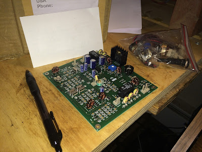
I am having a really EXCELLENT radio morning here at SolderSmoke East coast HQ. I made some progress on the Armand HRO receiver — just squaring away some of the too-long leads and improving the shielding a bit. Then I was looking out the window as the mailman arrived. What was that little box he was leaving us? Wow! A box from Hyderabad! The BITX 40 module arrived, wrapped in a very interesting piece of Hyderabad newspaper. Very FB. Thanks Farhan. I will surely be writing and talking about this rig in the weeks to come.
UPDATE: I just realized that the BITX module fits very nicely into a TenTec TPC-45 cabinet that Armand gave me a while back. TRGHS.
Cool Jazz from New Zealand as Heard on a Homebrew Superhet Receiver (VIDEO)
I’m making slow but steady progress on this one. The origin of the project was the beautiful National HRO dial and gearbox that Armand WA1UQO gave me.
I decided to use a 455 kHz IF because;
1) That was the IF of the old HRO receivers (the ones that won WWII)
2) I had a nice TOYO CM455 crystal mechanical filter that would be good for SSB.
3) I figured it would be easy to add in a wider filter that would be good for AM shortwave listening.
4) I like to keep the IF below the frequency of the VFO.
The wide filter turned out to be harder than I thought, but I think I have finally achieved the selectivity I was looking for. I’ll have a switch on the front panel that will allow me to go from “AM-Wide” to “SSB Narrow.” The switch will change the filters and the detectors, and will turn the BFO on and off.
Still to do: I need a high-pass filter to knock down RFI from nearby AM broadcast transmitter. And an RF gain control would be nice.
I’m really glad Radio New Zealand is there. It provides welcome relief from the shortwave fire and brimstone. Radio Romania is also doing a fine job on shortwave.
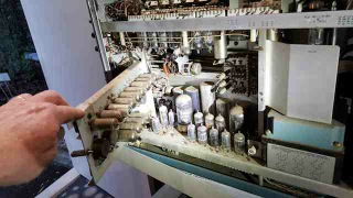
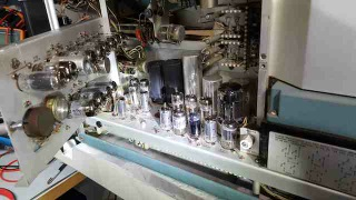
The Last Hallicrafters Transceiver…REBORN! TWICE!
Pete Juliano and his colleague Giovanni Manzoni led me this morning to the happy land of Hallicrafters hybrid nostalgia.
It all started with Pete’s latest blog post:
http://n6qw.blogspot.com/2016/10/more-junk-box-rigs.html
I admit that I had never even heard of the Hallicrafters FPM rigs. Pete’s (uh, I mean Giovanni’s) video show’s Pete’s junk-box rebuild of the old rig. Very nice. Note the presence of the Si5351…
I needed more background info, so I turned to YouTube. This led me to more old friends: Dale Parfitt W4OP has a really nice video of his rebuild of the Halli FPM rig (see above). From his video we learn why Dr. Juliano prescribed a dose of Si5351 for the patient: Dale tells us that VFO instability was a major problem with this rig. Dale fixed his with the addition of an X-Lock board from yet another friend of SolderSmoke: Ron G4GXO of Cumbria Designs.
Dale really out-did himself by building an add-on accessory box for the FPM. Very nice. I especially liked the addition of the W3NQN passive audio filter for CW. I always have misgivings about adding audio filters to Direct Conversion receivers — this will reduce QRM, but you are still listening to both sides of zero beat. But when you add a sharp CW audio filter to an SSB superhet you will end up with true “single signal reception.” FB Dale.
Please send Pete Juliano and Giovanni Manzoni some positive feedback and words of encouragement. Please urge them to keep up the good work on the blog and the videos. Theirs is sometimes a lonely task — without feedback it can sometimes seem like putting messages in a bottle and throwing them into the digital sea. Please let them know that their work is being seen! Leave some positive comments on Pete’s blog. (No snark please — The Radio Gods will retaliate if you harsh N6QW’s mellow.)
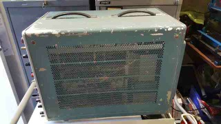
Oz Tektronix ‘Scope Repair (in Juliano Blue)
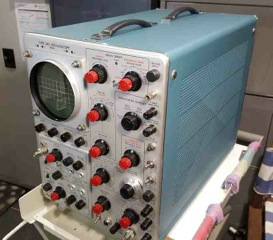
Rob is a braver ham than I. When my Tek 465 quit, I tried to fix it, but quickly chickened out.
Very nice that he painted his in Juliano Blue.
Dear Bill and Pete,
I do enjoy your podcast, and I must present an offering to the “Gods of Homebrew”,
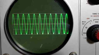
An on-line find of an old Tek 545 oscilloscope presented a chance to enjoy the warmth of 100+ tubes (once repaired)
The outside was heavily scratched, the inside looked like a chicken coup, but no major bits missing or broken.
Lots of cleaning, testing all tubes,(using the excellent uTracer tube tracer), replacing the broken 3, remounting the cooling fan, lots of reading about tube oscilloscopes, adjusting the trigger circuit, rebuilding 3 electrolytic power supply capacitors, sandblasting the cabinet and a coat of BLUE paint.
Voila, the joy of (visual) oscillation! (1MHz 2V p-p)
Rob VK5RC
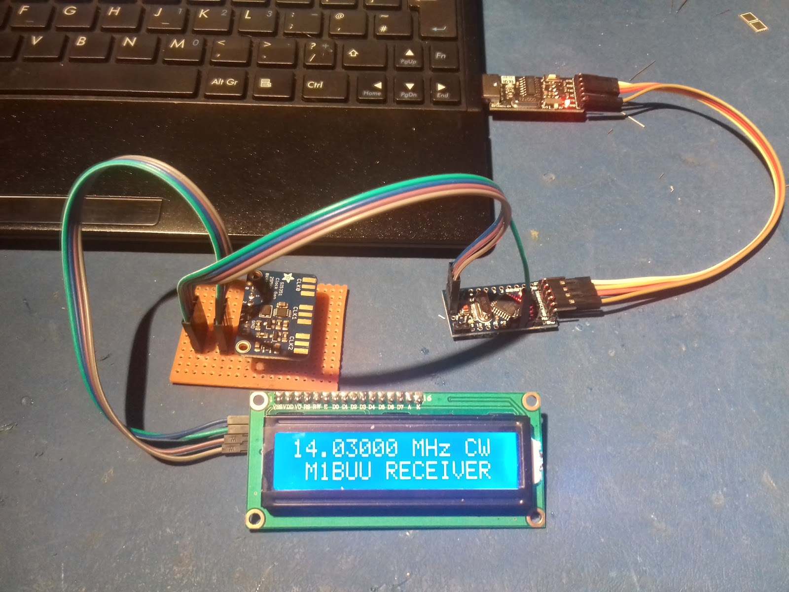
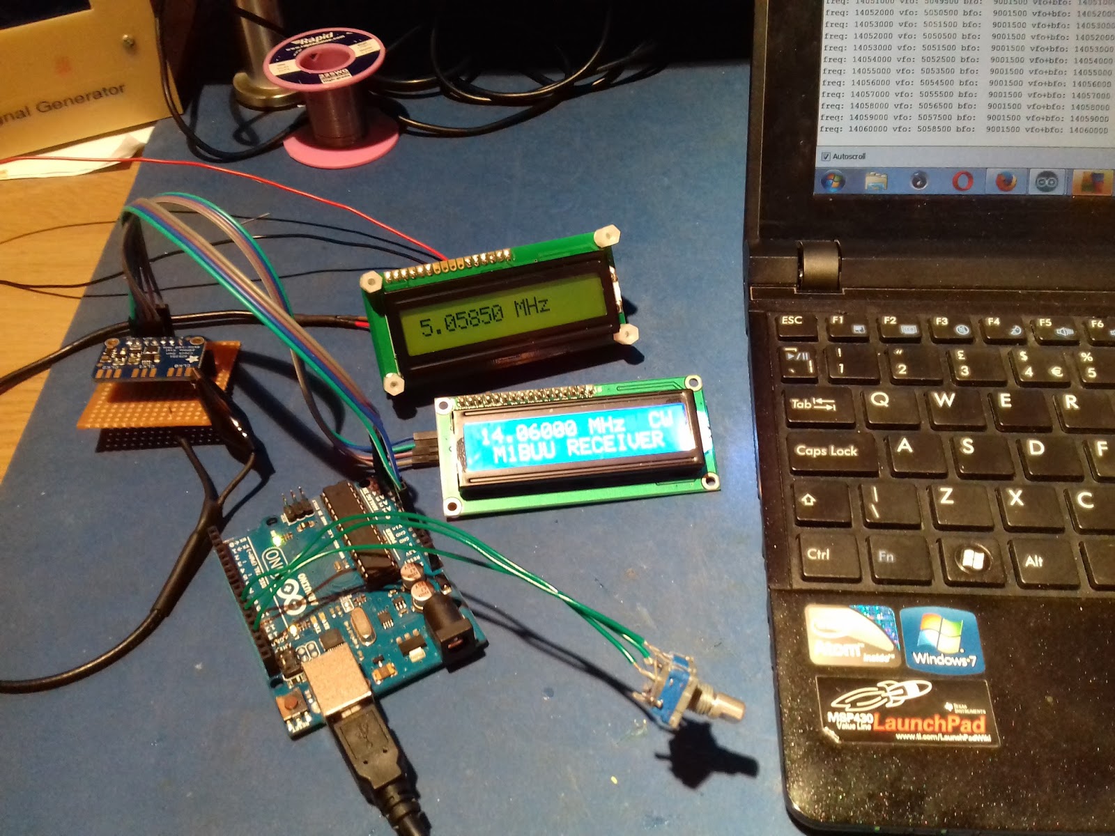
Colin M1BUU’s New Receiver Project

Hi Pete,
Just checking in 🙂
I have actually been melting solder recently. I decided to build a little CW receiver. I love my regenerative RX that I built as a teenager, but after all these years, I’m tired of constantly tweaking the controls!
My project is a 20m CW only superhet receiver with a 9MHz home brew filter. I’m using the SI5351 for the oscillators. I originally thought I would cover multiple bands, but for now I have the parts for 20m coverage. I might tinker with other bands at a later point.
I’m using your LBS code on the Arduino, the one for 20m with 9MHz IF. I haven’t applied power to the rig yet but it’s not far off fully built. I tweaked the Arduino sketch using my Uno and tonight I have successfully transferred the code to a Pro Mini. (Code went into Pro Mini on first attempt – amazing!).
73 for now,
Colin M1BUU
Beautifully Ugly! A Homebrew Receiver from the Netherlands (video)
This one is similar to the receiver I’ve been working on: middle of the HF band, discrete components, all analog, 455 kc IF, wooden chassis, eclectic circuit boards. Very cool.
The builder is Ko Tilman. His YouTube channel is here:
https://www.youtube.com/channel/UCqe1Y4StR9cZ8BQDWuoMq9w
I came across Ko’s channel when I was looking for a circuit for an AM detector. I have been experimenting with the standard one diode and two diode (Germanium) circuits, but the receiver doesn’t sound very good when using these circuits. Any recommendations for something a bit better (without getting carried away with complexity)?
About Ko Tilman:
Smoke-Free! On the Air with the W1REX Dayton Hamfest Buddy
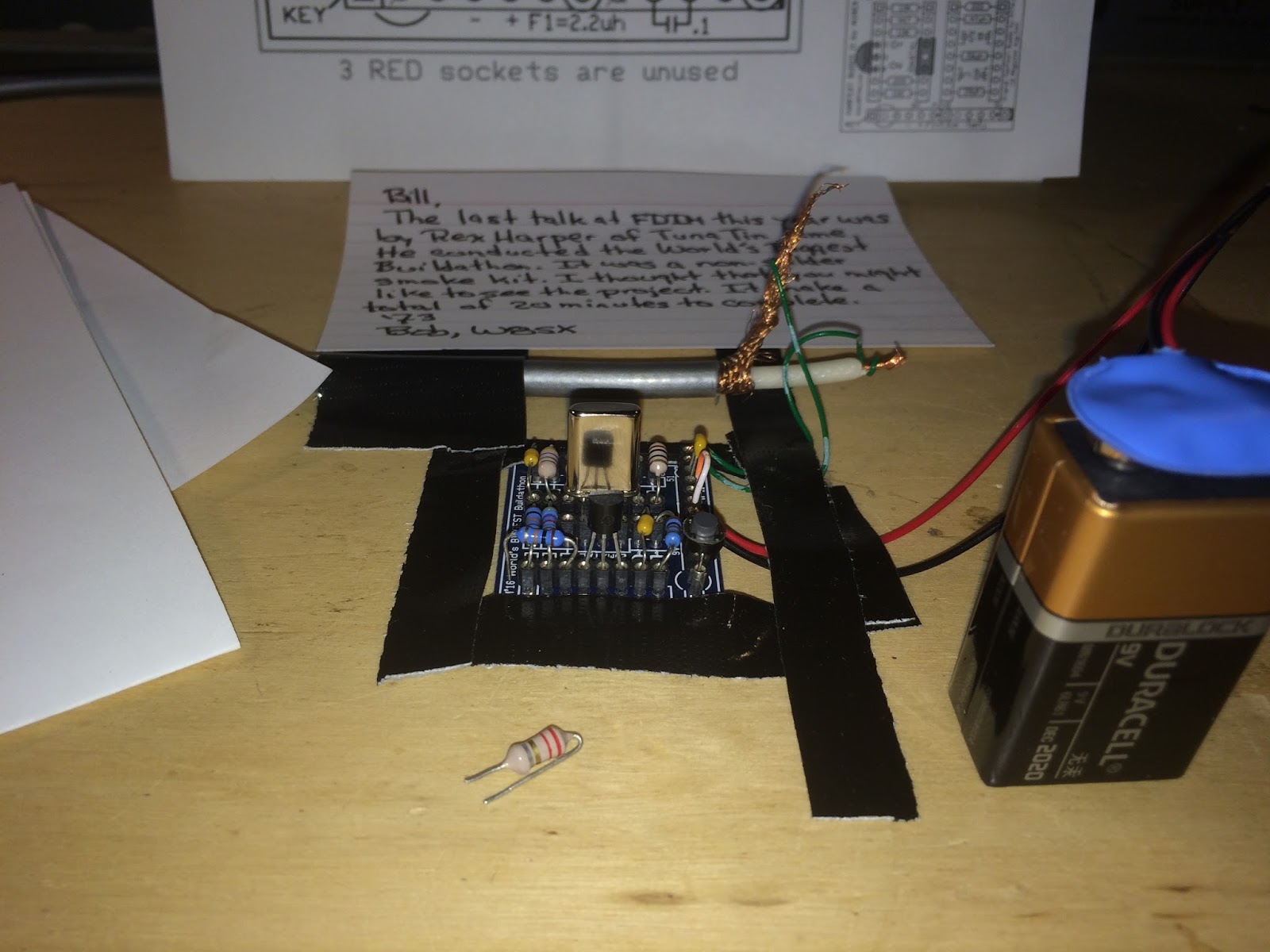
After the Dayton Hamvention, our ace correspondent Bob Crane (W8SX) sent me the “Hamfest Buddy” kit that Rex Harper W1REX had put together and used in “The World’s Biggest Build-a-Thon.”
It is a single 2N2222 crystal-controlled oscillator for 20 meters. All the parts are plug-in — no solder smoke is released. Mine went together in about 15 minutes and fired right up. You can see it above. It runs off the 9V battery. I had to hold it down with tape. You can see the key button in the lower right. That little inductor in the foreground is used to shift the frequency a bit. I had to remove the 10K resistor in the emitter circuit because with my antenna the circuit was going into low-level oscillation even in key-up. With the 10K resistor removed, this problem disappeared.
I hooked it up to my 20 meter dipole and called CQ. With only about 60 milliwatts into a dipole under poor conditions, I really didn’t think I’d get any answers. But I figured the Reverse Beacon Network might pick me up. It did:
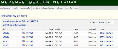
Thanks Bob! Thanks Rex!