We’ve had some pretty amazing contact with Kevin AA7YQ over the years. Kevin and I originally bonded due to our common experience with parachutes (he was smoke-jumper, I jumped while in the army). Kevin once used a parachute to insulate a QRSS beacon. And one day, while thinking about SolderSmoke during a drive through Montana, Kevin turned on his rig only to hear… ME! He caught one of my infrequent CW contacts. TRGHS.
Now we hear that OM Kevin may be poised to end the HDR-SDR civil war that has for so long been dividing our great podcast. Can Kevin’s new rig heal our wounds and allow us to enjoy the beauty of SDR waterfalls while not forsaking the joy of hardware defined rigs? Kevin will soon launch a blog describing his effort at rig-building. See below for a preview. Stay tuned.
Kevin wrote:
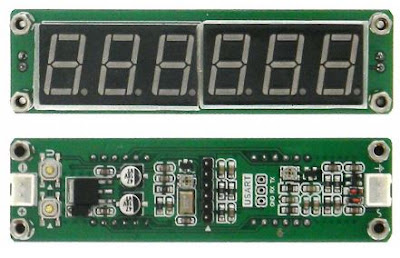
I am currently working on a new rig design. It is a hybrid HDR(Hardware defined)/SDR radio that incorporates some classic superhet design along with some of the more useful features of SDR. I have found that pure SDR is really not that enjoyable for me. I love using GNU radio to mock up and test design concepts, but SDR basically dilutes the “magic” of radio to nothing more than software and touchscreens, stuff we use every day all day. Its not the Ham Radio I grew up with as a kid and was fascinated by. On the other hand, I have always fought temperature drift, large variable capacitors minimal tuning range, and associated with classic VFO and VXO designs. In fact, in 1997, for my senior capstone design in EE at Montana State University, I designed a 20m superhet that used a DDS LO. At the time DDS was cutting edge technology I used an AD7008JP50. I had to beg and plead with ADI to get a couple samples for my design, since they exceeded my self-funded college student project budget. 😊 But that’s another story. SDR has made me grow extremely fond of the waterfall display. I love having the visual “situational awareness” of what is going on in a moderate bandwidth outside of the spot I am tuned to. I also am a big fan of digital filtering and modification-ability that comes with boot-loadable microcontroller designs. So this design includes most of the real highlights of SDR but does not take the fun out of designing, building, and operating a HDR.
Anyhow, this design is a big goal of mine to complete and build in 2021. I am not retired yet so I still have to balance, work, family, and tinkering time, but I am very excited about this project. I have “noodled” this design to the point of what I have achieved full-on “analysis paralysis”. That is, I keep designing and redesigning, optimizing, and figuring to the point where after months of thought, I have nothing to show for it 😊. So my New Years goal for 2021 is to make “good enough” rather than “perfect” design decisions and move forward. I will keep you posted on the design and possibly start a blog so I can get some peer review input from the greater RF Design/Homebrew community on my project. I’ll keep you informed on my progress.