Fresh from a great success with the use of the M0XPD divide by 4 I and Q VFO in my Frankenstein Phasing Receiver, I got ambitious. And greedy. I wanted more. More frequency coverage. More bands. Divide by 4 can really limit your frequency range. The AD9850 only goes up to 40 MHz. Divide by 4 and you can’t even get the 30 meter band.
So I started looking at other options. Si570 looked nice, but here the lower limit was the problem: 10 MHz. Even with divide by 4, that knocks out 160 meters, a band I am very interested in lately, and that seems to sound especially good in a direct conversion receiver.
Once again, the controversial Si5351 was calling my name. It would go down to 8 kHz and up to 160 Mhz. Woo Hoo! If I could build a divide by 2 IQ VFO, I could cover 160-6 meters.
Here is the basic idea. From:
http://www.markimicrowave.com/blog/2015/04/top-7-ways-to-create-a-quadrature-90-phase-shift/
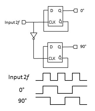
The Flip Flops are set up to change state when the input signal is going up. By putting an inverter at the input of the bottom FF input, in effect you have that one changing state when the input signal is going down. Look at this for a minute or so. Look at the square waves at the bottom. See it? See how it takes an ordinary signal and spits out two signals, one 90 degrees off the other? Pretty cool, don’t you think?
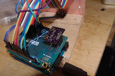
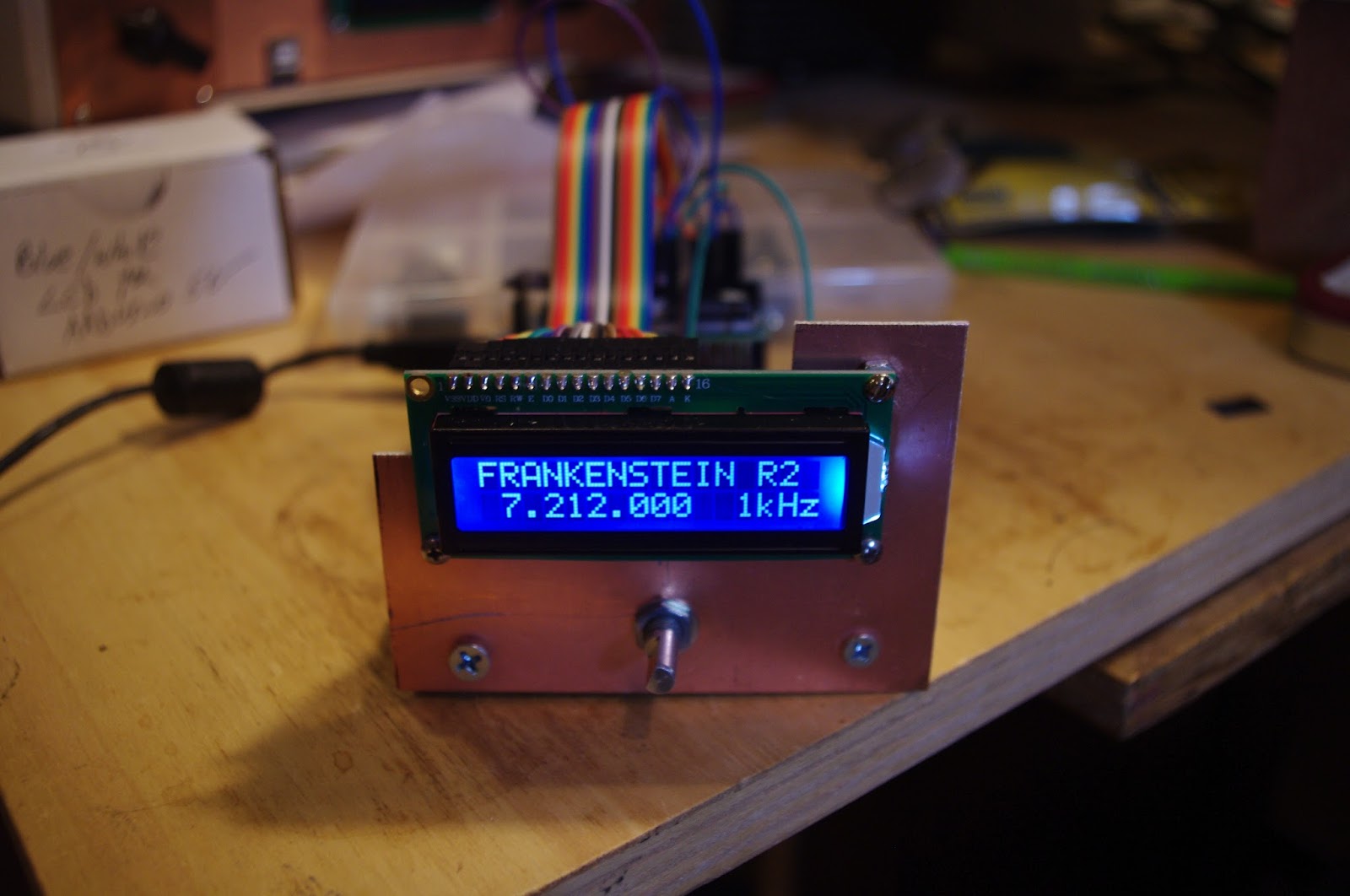
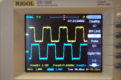
With lots of hardware help from Todd VE7BPO, and software help from Tom AK2B (wizards both), I got my Si5351 divide by 2 circuit working today. You can see the resulting I and Q in the picture at the top. But I am discovering that there may have been wisdom behind those divide by 4 circuits. My opposite sideband suppression isn’t as good with this /2 scheme as it was with the AD9850 divide by 4. I’m still trying to figure out why. I may have to go back to divide by 4. Stay tuned.