Why building oxygen concentrators is NOT rocket science.
To make a donation:

Serving the worldwide community of radio-electronic homebrewers. Providing blog support to the SolderSmoke podcast: http://soldersmoke.com
I’ve been using the Gilbert Cell (in its NE-602 form) for many years. It was in the G-QRP Sudden Receiver. It was in the Neophyte receiver, it was in that little 20 meter DSB rig that I used in Rome and the Dominican Republic. But truth-be-told, every time I used one I heard Jean Shepherd’s voice in my head, razzing me about the fact that I didn’t really understand how the Gilbert Cell works.
My ignorance was kind of understandable, the Gilbert Cell was built around a circuit rarely used in ham radio: the differential pair. And Gilbert used three of them.
My most recent use of the G Cell came after I watched Mike WU2D’s videos on upconverters for the RTL-SDR Dongle. I had an NE-602 all boarded, boxed and socketed, so I used it in my version of the upconverter. But as I did so, I pledged — this time — to really learn how it works.
So I started cracking the books (and the internet) on the Gilbert Cell. It is a very interesting circuit. Gilbert was working to come up with a double balanced mixer that could be built on a chip without the use of the big toroids that we have in our diode ring mixers.
From my study of other mixers I knew what was needed to get two signals to really mix: You needed a non-linearity. You needed the gain or loss experienced through this non-linearity by one of the signals to be determined by the level of the other signal. If you had this, you’d have at the output a complex repeating wave form. Fourier told us that this kind of waveform has within it a number of sine waves and that among them will be one at the sum frequency of the two waves and one at the difference frequency. That’s mixing in a very small nutshell.
Descriptions of the Gilbert Cell usually begin with single differential pair with a current source controlled by another amplifier connected to the emitters in the two transistors in the differential pair:
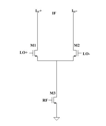
The gain of the M1 M2 differential pair will be determined by how much current current is flowing into their emitters. The signal coming into the RF port will control this current. So, assuming there is some nonlinearity in these circuits, RF will mix with LO and at the IF you will have sum and difference frequencies.
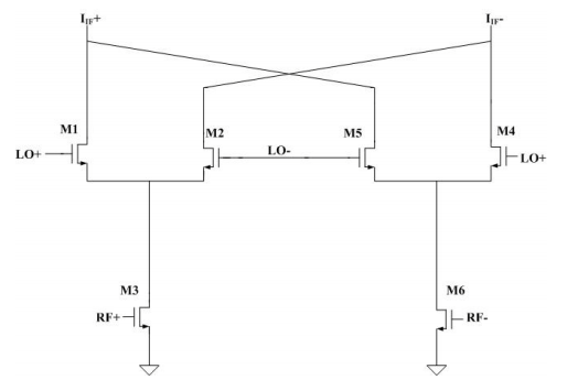
The problem is that you will also have the LO signal there. A singly balanced mixer balances out one of the inputs. A doubly balanced mixer balances out both. Gilbert came up with a way of eliminating both input signals without having to use the big inductors that are used in diode mixers.
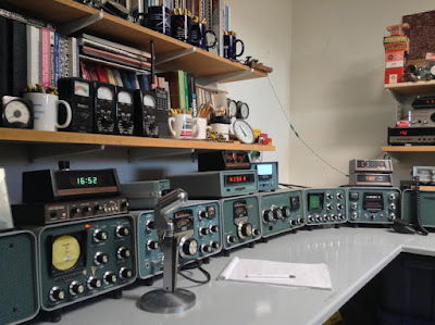
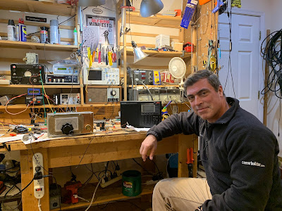
WA7ZZE Shack
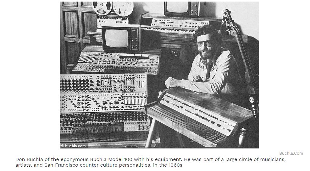
Oh no, here’s something else for us to worry about when working on old gear. As if the treat of electrocution or radioactive poisoning were not enough, now we have to worry about being hit with a dose of the 1960’s drug culture. That could be one bad trip indeed. Imagine if you were having a hard time troubleshooting the Buchla Model 100. All of a sudden things start getting weird and your test gear starts dancing on the bench.
Fortunately, this is not likely to happen with a rig like the DX-100. With rigs like that the only similar danger is nicotine poisoning.
Thanks to Stephen Walters for finding this groovy story.

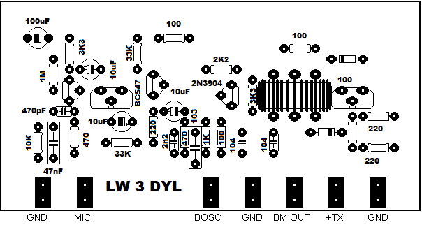
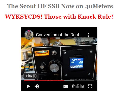
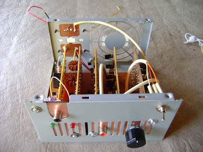
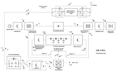
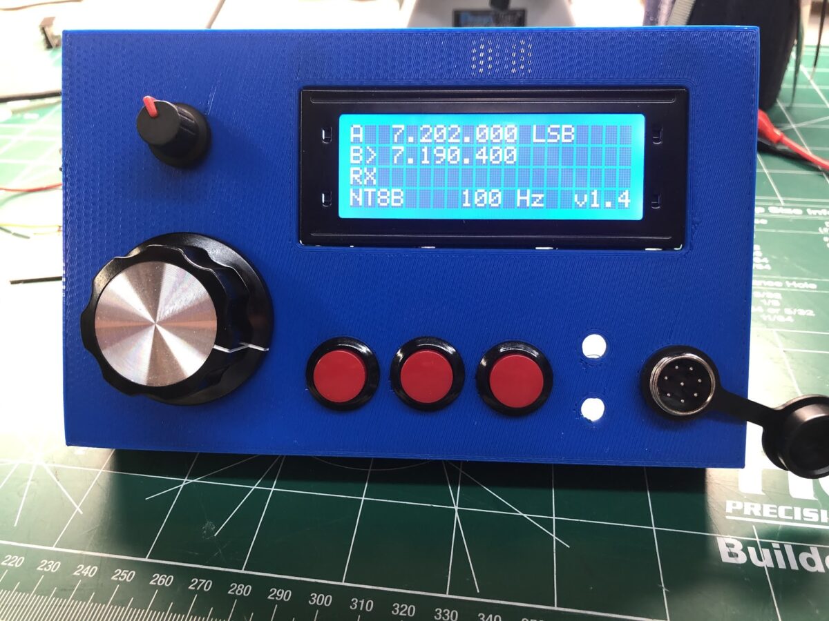
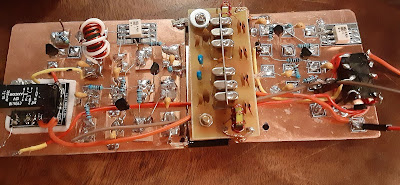
Really nice work. BLU is Spanish for SSB. (Juliano BLU?)
But I think Guillermo needs to build ONE MORE BOARD! A VFO or a VXO. Analog. To finish the job. Guillermo tells me this is in the works — he selected an IF of 11.0592 MHz specifically so that he can use a variable oscillator built around a 4 MHz ceramic resonator.
Complete schematic and PC board patterns on his site:

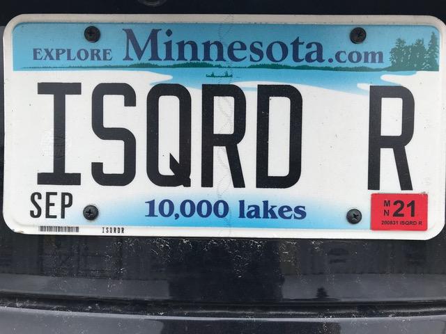
We are proud to say that the owner is a SolderSmoke listener. Can you figure out what kind of car he is driving?
(See comments for answer).


From the obituary in the Washington Post:
In addition to the Nobel Prize, Dr. Akasaki’s honors included a 2009 Kyoto Prize — Japan’s highest honor — recognizing developments in advanced technology. He found that some technology, however, needed no advancing at all. He took great pleasure, for example, in long-playing classical music records.
On that point, he joked, “I am analog.”