Mythbuster Video #3 — Using the VFO from a Yaesu FT-101

FT-101 VFO
I used LTSpice and Wes’s FBA program (from LADPAC) to come up with a circuit that would provide the needed gain. I needed to get the 290 mV rms signal (across a 50 0hm load) up to the 500 mV rms signal needed by the ADE1 mixer. Above is the amplifier that I came up with. The key here is to adjust R2 and R1 to get the required gain.

My Current Rig: The Quarantine Hodgepodge

As I continue to Stay In The Shack, last week I was looking for something to do. This is what I came up with.

Left to right:
— Speaker
— Ramsey-kit QAMP20 modified for 40. I now have two MTP3055V MOSFETS in there.
— BITX40 Module with a solidified VFO from a Galaxy V (note the knob from a Drake 2B!)
— Power supply

It puts out about 15 watts SSB. I was bracing for attacks from the 40 meter waterfall police, but no, everyone said it sounds great. I had four very nice contacts yesterday. It was fun.

Still to do: Possibly a San Jian frequency counter to give some Juliano Blue glowing numerals for the frequency readout. This would be a step up from the Juliano Blue sticky note and corresponding piece of black electrical tape that currently serves as the frequency indicator.


The VFO that I am looking for: The Globe VFO deluxe

I mentioned this in the last podcast. I’m looking for one of these. I had one as a kid, and used it with a DX-40 and a Lafayette HA-600A. It is now the only piece of gear that I need to recreate my novice station.

Does anyone have one of these, perhaps gathering dust in some corner of the hamshack? Please let me know. Thanks.
Here’s the manual:

SolderSmoke Podcast #222 Antennas, Phasing, VFOs, 2-Bs, 6 years of N6QW, MAILBAG

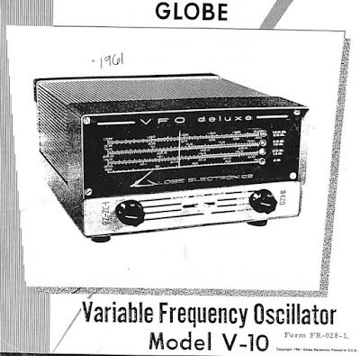
After 46 years, finally a dial skirt
SolderSmoke Podcast #222 is available:

No travelogue but… SolderSmoke Almanac!
Memorial Day in U.S.

End of Ramadan so Eid Mubarak!
#222 marks SIX YEARS of Julian-ismo. He started on SS 161. Thanks Pete.
Thanks to all who sent good wishes on Billy’s graduation. He heads to Boston and the lab in a week or so. Very proud.
——————————————
Bill was on Ham Radio WorkBench Podcast
—————————————–

PETE’S WORKBENCH
— Antenna Ideas — Don’t Buy that $165 dollar dipole! It is just wire!
— THE PHASING RIG. Does this point to a need for meditation? Or at least some temporary disengagement? Tribal wisdom from Pete.
— DEAN KK4DAS’s rig. The Furlough 40. Troubleshoot. Tribal knowledge.
——————————————-
— SHAMELESS COMMERCE DIVISION: AMAZON BOX — SEARCH FOR ANYTHING OU WANT THERE.
— PLEASE PUT COMMENTS ON THE SOLDERSMOKE BLOG POSTS.
PLEASE CHECK OUT THE SolderSmoke YOUTUBE VIDEOS.
——————————————

BILL’s WORKBENCH
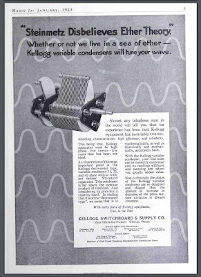
n Shortwave dials and exotic locations. Java!
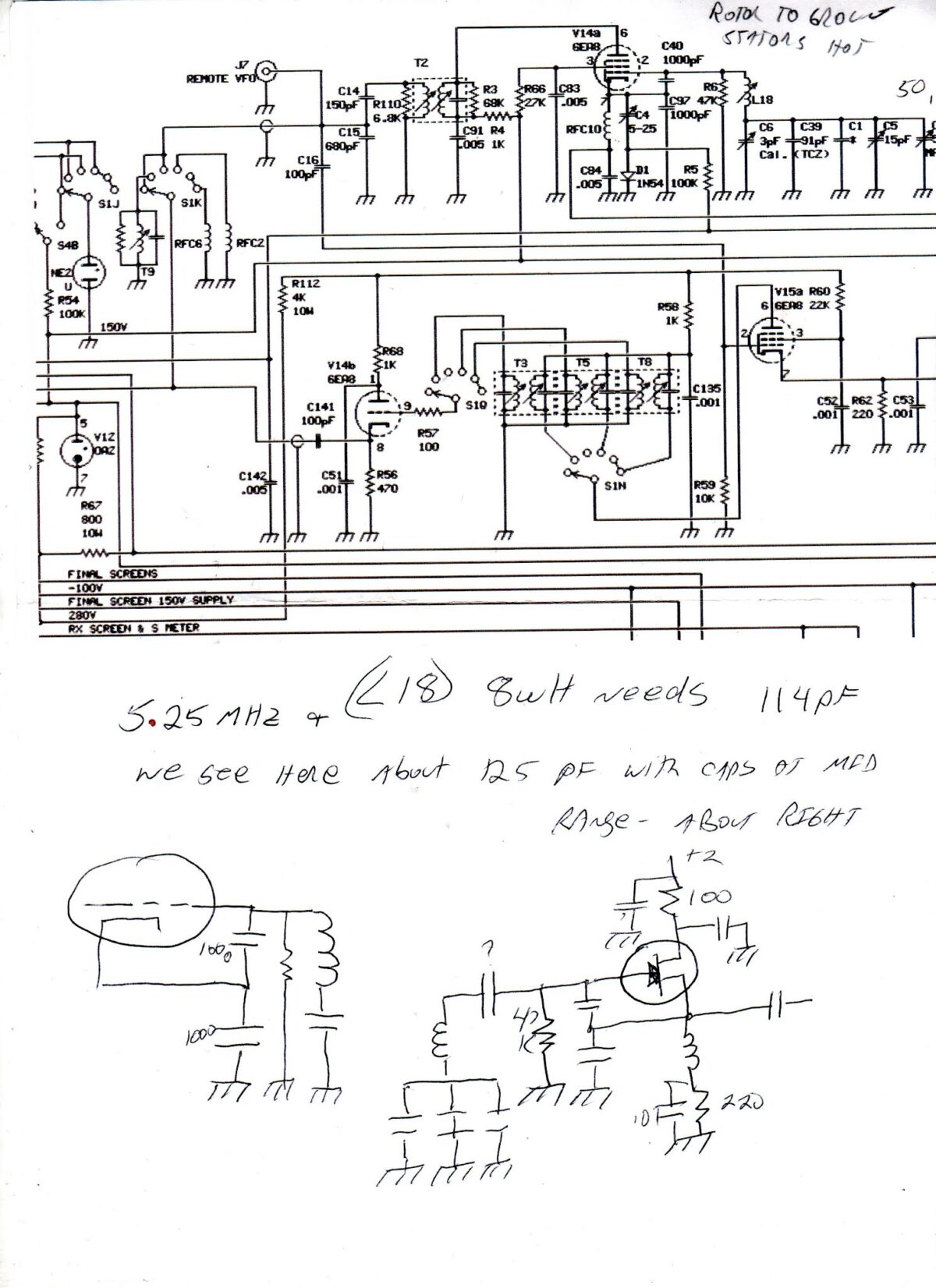
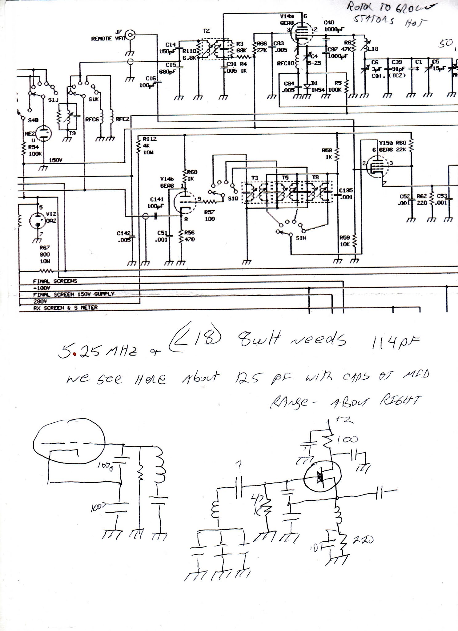
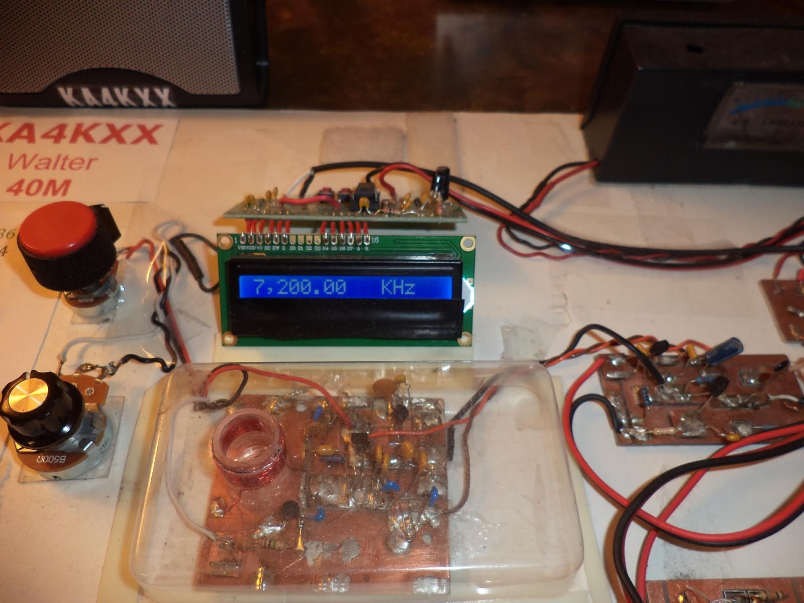
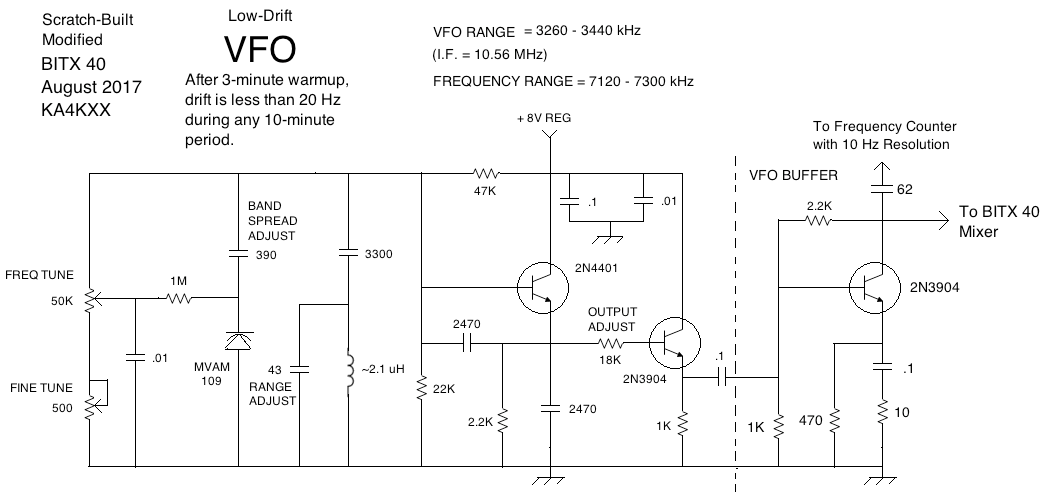
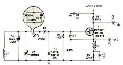
n Galaxy V VFO Project. Series-tuned Colpitts.
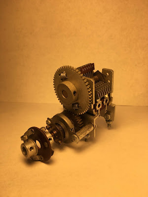
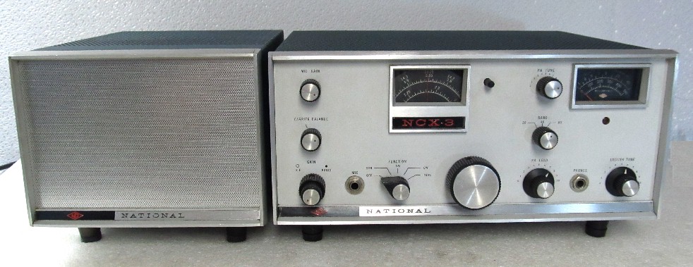
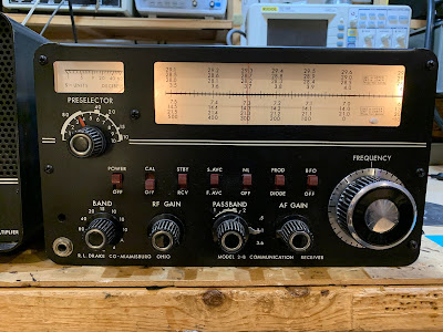
n DRAKE 2-B. Hayseed Recap. Put the skirt back on the old rig. Reduction drives?
SHOPPING BAG:
I got a replacement for the Xtronics 4000 soldering station. Yaogong worked!
Ordered screws and stuff from McMaster — Came very fast!
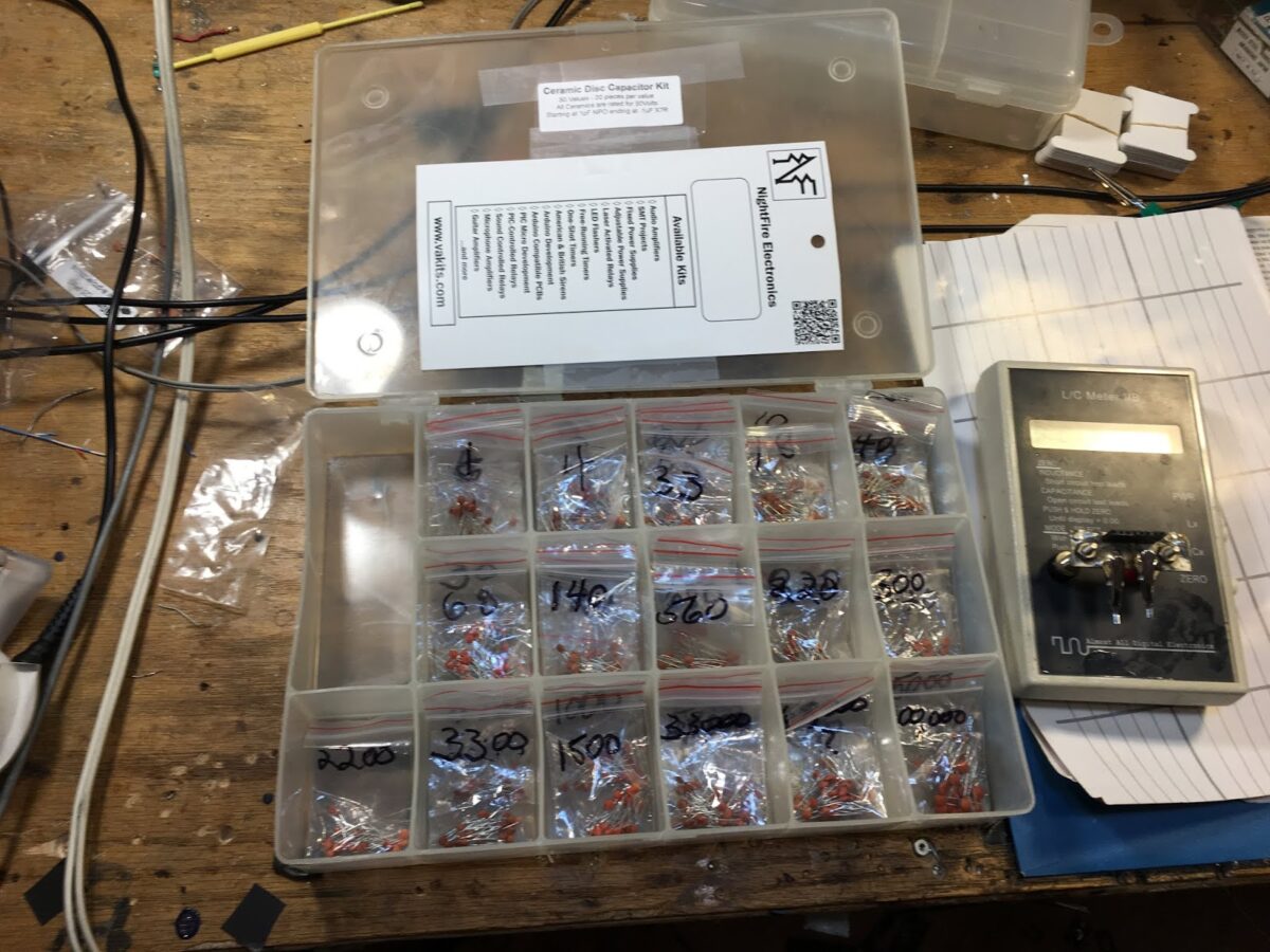
Working on a resistor kit from Mouser.
MAILBAG:
VK2BLQ’s Phasing RX with an HRO dial. Cool Retro.
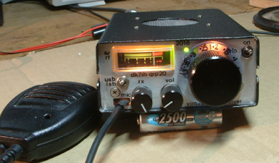
Adam N0ZIB — Cool station. TFT screen Aluminum welded box. FB.
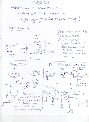
Karl G7AFT BITX 40 doing USB and LSB by changing the VFO freq. Pete’s trick!
Jerry KI4IO out in nearby Warrenton. Hope to be able to meet up soon.
Keith N6ORS’s Hot Mustard Phasing Board.
Mike N5GTF’d FULLY INDOOR Quarantine Receiver. Need a slogan for the antenna!
Nick M0NTV’s Bread Bin 80 Quarantine rig
Bruce KC1FSZ Quarantine 10 — Brave man in solar minimum. But I hear 10 is opening.
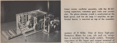
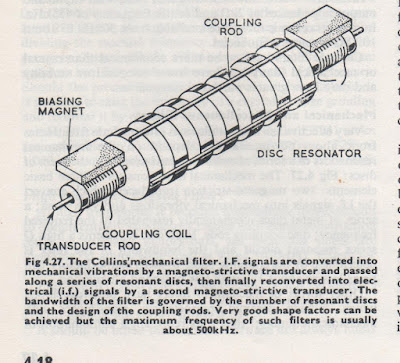
Talking to Grayson Evans KJ7UM TA2ZGE about Collins 9.9 MHz transformers.
Talking to Alan Wolke W2AEW about Drake 2-B stuff Was there a reduction drive?
Paul VK3HN about Ceramic filter spurs.

Peter VK2EMU notes no animals were harmed in the making of my videos. But many electrons were agitated.

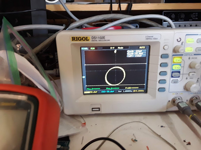
N6QW Phase Shift Success — It aint over ’till the fat lady sings


Video on the Galaxy V VFO Project

This is the second version of this video. I had some technical difficulties getting it to upload in High Definition, but I was able to work it out in this version.

In this video I describe the VFO project, talk about how I made use of the e-bay Galaxy V parts, talk about the circuit (series-tuned Colpitts), conduct some stability tests, and discuss many of the ways a VFO like this one can be useful to the radio amateur.

Thanks to Pete Juliano for inspiring this effort.


Walter’s VFO

Main VFO board under plastic — buffer board off to the right

There is a lot of tribal knowledge in this short article by Walter KA4KXX. (The most recent issue of SPRAT has a picture of a SPRAT cover from more than 30 years ago, announcing an article by Walter. OM has been at this for quite a while.) Walter’s advice is similar to that of Doug DeMaw, especially on the air-core coil. FB Walter, thanks for sharing.

Regarding the last line in Walter’s article, please direct any complaints about drifting analog VFOs to Peter Juliano. He will be delighted to receive these complaints, and will promptly provide all correspondents with very succinct advice on how to overcome the instability.

My Way to a Low-Drift Analog VFO, by Walter KA4KXX


I recently built a digital VFO (from a QRP Labs Kit) to see what everybody is talking about, and it has been quite handy for my first two-band homebrew transceiver, but by the time one adds the low pass filter, a low-level RF amplifier to boost the weak output, a 5 VDC regulator, and a hefty +12VDC power line filter to the beast to keep the digital noise out of the rest of the radio, for a single band project I still prefer a low-drift analog VFO.

My approach to minimizing drift is very simple and works well for a VFO range of 3 – 7.3 MHz, which is all that is needed for the 20 to 80 Meter bands, either direct conversion (adding a doubler for 20M) or single conversion with approximately a 10 MHz IF.

First, see my schematic (adapted from Small Wonder Labs 40+ transceiver, original BITX40 Analog VFO, and other sources) and wind an air core inductor with stout magnet wire such as 24 or 22 AWG. Use a thick, rigid plastic form of a diameter so that you need about 12 turns, and single coat with water-based sanding sealer, Q-dope, or similar. Use hot glue to mount the coil firmly to the single-sided circuit board, and build a cover of some type, especially if the radio is to ever be used outdoors.

Second, all the VFO capacitors (except power supply bypass) should initially be the modern C0G type, which can be obtained from Mouser (such as TDK FG28C0G1H681JNT06 or the like), which I trust more than those labeled NP0.

Then, power up the VFO and tweak the coil, tuning arrangement, and range capacitor to get the frequency range you desire.

Next, monitor the drift from a cold start to see how fast it is moving as it warms up, and whether it stabilizes nicely (my goal for SSB Phone use is less than 20 Hz drift during any 10 minute period) after 10 – 15 minutes maximum. If it does not stabilize to your satisfaction, then start substituting polystyrene caps for the C0G units one at a time until you are happy with the performance.

[Also remember that a stable BFO is important as well, and if you use the BITX 40 crystal oscillator design, I recommend installing a dedicated 78L09 power line regulator.]

If you build this VFO at the higher (7 MHz) frequency end, just change the inductor value to about 0.5 uH, with everything else about the same, but expect to do more tweaking to get stability, and the warm-up time may be closer to 15 minutes. After years of experimenting, this is what has worked for me. If it works for you, please send me an email (see my QRZ page) of thanks. If not, file a complaint with Soldersmoke.

These Variable Capacitors Work — Ether or No Ether!

Amazing that the arguments about the presence or absence of a luminiferous ether made its way into parts advertisements in a radio magazine. This is from Radio for January 1923. (About 18 months before my dad was born.)

BTW that capacitor looks very nice, and would almost certainly still work. I have caps like that in my junk box. The shape of the blades helps address one of Pete Juliano’s complaints about analog oscillators — the inconsistent spacing of frequencies on the dial.

Thanks to the K9YA Telegram for posting this.

Making Fish Soup from Herring and Tuna (How to Build a Fish Soup 10 Transceiver)

Just in case some other fanatic someday thinks about trying to turn a Herring Aid 5 and a Tuna Tin 2 into a Fish Soup 10. This will also serve as a note to myself on how I did this. Above are my suggestions on how to get the VFO signal into the transmitter and the receiver. Both RX and TX can easily be returned to their original condition.

Peter DK7IH’s Amazing Rigs and Blog

It has been a few years since we last mentioned Peter DK7IH. He has continued to melt solder and to document his work on an excellent blog: https://radiotransmitter.wordpress.com/

I was especially interested in the rig pictured above. NOTE: NO GLOWING NUMERALS. That rig has an analog VFO. The blog article provides some great pointers on how to achieve thermal stability. Also, be sure to check out his “Old School” rig.

I’ve put Peter’s blog in the blog listing on the right side of the SolderSmoke blog.

A Beautiful Variable Capacitor (from Pete)

Is this a thing of beauty, or what? Pete sent this to me back when I was having trouble finding a “smooth running” variable cap for my HRO dial receiver. It has a standard Jackson Brother’s reduction drive attached to the shaft, followed by a really cool gear arrangement. Note the spring loaded teeth on the big gear — that is to keep the gears tight when turning in both directions.

As was the case with the HRO dial that Armand sent me, the beauty of this part will cause me to build something with it, really just for the purpose of putting it to use. We’ve been talking about double or triple conversion superhets with 100 or 50 kHz final IFs. At those frequencies you can get good selectivity with LC filters. As with the Drake 2-B. Steve N8NM is sending me a dial that will go well with this part. That will add to the already abundant mojo/juju. I feel a VFO in the works. Thanks to Pete for being so supportive of my luddite analogism.

SolderSmoke Podcast #210 Boatanchors, Magnetostriction, VFOs, AM, CW, SSB, Mailbag

2 March 2019

SolderSmoke Podcast #210 is available:

http://soldersmoke.com/soldersmoke210.mp3

Alexa, Marie Kondo, berets, and ham radio

Bi-Coastal Boatanchors
BATTLE CRY: The Vintage SSB Preamble! “We are NOT ashamed!”
Bill’s HT37 and Drake 2B
Pete’s National National NCX-3 TRGHS
Mechanical Filters
Magnetostriction
Why did Collins go with mechanical vice crystal filters?
The foam deterioration syndrome in mechanical filters. Sad.
Please send any unwanted Mechanical Filters to Bill.
BONUS QUESTION: Look at the filter below. What is different/special about this one?

Pete’s antenna trouble
Pete’s FB amplifier troubleshooting
Recent improvements in the uBITX finals
Pete’s design for a VFO for Bill (and an indoor antenna tuner!)

Bill’s VFO for Pete: HRO dial and gearbox driving a rotary encoder

Guido PE1NNZ puts the QCX on SSB
“The Secret Life of Machines — Radio”
HB HRO dial from DL6WD
WA1QIX’s USB D-104
“The High Frequency Oracle”
DeMaw’s LC filter receiver
Godzilla and Ham Radio
Bill’s poor quality SSTV images from space (what happened?)
Listening to AM on an SSB receiver
Mixed feelings about CW

MAILBAG
M0KOV’s mom took him to the doctor due to THE KNACK.
M0JGH getting married (ALWAYS LISTEN TO PETE!)
Jac’s FB Receiver

What is different/special about this one?

A Homebrew HRO Dial by DL6WD, Homebrew Hero

Take a look at that beautiful rig in the bottom of the cover pictures. (A closer shot appears below.) That is an HRO dial, right? Or is it?

No, it is not. In the picture we see the homebrew receiver designed and built during the 1960s by Rudolf Fishcer, DL6WD. It is magnificent in every respect. Because I have been working with the HRO dial and gearbox given to me by Armand WA1UQO, the tuning dial on this receiver caught my attention.

Here is what DL6WD says about this part of his project: “The main tuning gear was built around a BC-221 tuning capacitor and reduction gear. The counter dial and tuning knob are the result of four weeks of labor, The counter dial reads in tens of kHz, where the main tuning knob has a calibration of 200 Hz per division, from an HRO inspiration.” The counter is in the little window to the upper left of the tuning knob. The window to the upper right is a phase-lock indicator. (See below.)

By the way, by the time DL6WD got finished with this all solid state receiver it weighed in at 52 pounds. Rudolf noted that “excessive shielding pays in electrical performance, but not in weight!”

DL6WD earns the title “Homebrew Hero.”

Switching to a Mechanical Filter from 1967 for my HRO-ish Receiver (with video)

From RSGB Handbook 1982


Having overcome the difficulties with the National NPW Dial and Gearbox, I turned my attention to the 455 kHz filter. I had been using this old Toyo CM – 455 kc filter (Date stamped August 1969). CM stands for “Crystal-Mechanical.” These filters are hybrid with some of the features of a crystal filter and some of the features of a mechanical filter. For more details go here:
https://soldersmoke.blogspot.com/2016/04/the-meaning-of-cm-in-toyo-cm-455-filter.html

I was disappointed by the CM filter. It seemed very lossey, and it just didn’t seem to be of sufficiently high Q — it seemed very broad. I could hear the other side of zero beat. It was barely a “single signal” receiver, and being “single signal” is the whole point of a superhet.

I remembered that Pete Juliano had sent me a Japanese-made 455 kc mechanical filter. Maybe this would do better. Last night I did a quick comparison test and — wow — Pete’s filter was much better. The Fifth Edition of the RSGB Handbook seems to agree with my assessment, noting that mechanical resonator filters were superior to the Crystal Mechanical hybrids (see pages 4.17 and 4.18)

Pete’s filter is from the Kokusai Electric Company. Part# MF 455 ZL. (Date stamped May 1967). “ZL”indicates lower sideband. I checked and indeed the passband goes from just above 452 kc up to about 454.5 kc. This is a 40 meter receiver and SSB on 40 is LSB, so this filter would work perfectly right? Not so fast! Sideband inversion had to be considered.

I was running my VFO from about 7455 to 7755 kHz. This means that the modulated incoming signal would be SUBTRACTED FROM the VFO signal to get to the 455 kHZ IF. And when that knd of subtraction happens, we have sideband inversion. The LSB signal will look like a USB signal when it reaches the filter.

My BFO was running right at 455 kHz, using a ceramic resonator at that frequency. I briefly considered just shifting it down to 452 kHz, but this proved to be difficult. Then I got a better idea.

I could just shift the VFO down to 6545 to 6845 kHz. This would mean that the VFO frequency would be subtracted from the incoming modulated frequency. There would be no sideband inversion. I had been thinking about doing this frequency shift anyway, thinking that VFO stability gets better as you go lower in frequency.

REMEMBER THE RULE: If you are subtracting the modulated (signal) frequency from the frequency of the local oscillator or VFO, only then will you have sideband inversion. See:
https://soldersmoke.blogspot.com/2015/05/sideband-inversion.html

Moving the VFO was easy. I am using a variable capacitor with several variable caps on the same rotor. I just moved from the smallest variable cap to the middle variable cap — this added capacitance to the system and lowered the frequency. I also added three additional turns on the coil. This put me very close to where I needed the frequency to be. I added one additional 9 pf cap and this put the VFO freq right where I wanted it.

I was really glad to include Pete’s filter in this receiver. The mechanical resonator technology fits very well with the very mechanical old-tech theme of this project (it already had a gearbox — a mechanical filter seemed to fit right in). It is a fascinating device — it is almost like having a set of tuning forks all tuned to 455 kc (see above for the RSGB description of how it works). And having it from from Pete adds a TREMENDOUS amount of mojo, juju, and soul to the new machine.

Icing on the cake: As I type this, I am listening to Fred K3ZO converse in Spanish with hams all through South America. Fred preceded me by three decades at the U.S. Embassy in Santo Domingo, but when I got there the local hams were still talking about him — he was much loved and admired by the Dominican hams. TRGHS. See Fred’s story here (scroll down a bit): http://www.gadgeteer.us/DRDISP.HTM

National Dial and Gearbox Problem Resolved

Thanks to all who offered advice and assistance. With help from you guys — and especially from Pete Juliano N6QW — I think I have this fixed.

Pete was right — the problem was really with the variable capacitor. The one I was using was kind of stiff and irregular in its motion. I found another one in the junk box that was easier to turn (it has one set of ball bearings). This fixed most of the problem.

I also spent more time making sure the shaft of the cap lined up perfectly with the shaft of the gear box. This also helped a lot.

I realize now that some of the “stickiness” that I occasionally feel while tuning may be coming from the dial — not from the gear box. It looks like my dial took a hit that slightly bent one portion of it. It seems that the numbers have a bit of trouble clicking over on that portion of the dial. Some lubricant may help there. But I can live with it.

The receiver now tunes very smoothly and I can go right back to a frequency and find the signal exactly where I left it. There does seem to be a very slight difference depending on whether I “approach from above” or “approach from below” — but this is not a big deal.

Check out the pictures of the receiver and the VFO. Note the “cardboard from a coat hanger” coil form. The winding is held in place with nail polish varnish. I had planned on having the variable cap, the coil , and the associated fixed caps all in a box for better thermal stability, but the VFO is very stable even without the box. I have the VFO running 455 kc ABOVE the signal frequency. It runs from about 7455 kc to about 7800 kc. I could have set it up to run 455 kc BELOW the signal freq. That would have made it a bit more stable (it is easier to attain VFO stability at lower frequencies) but VFO is so stable that I probably won’t mess with it. I followed DeMaw’s rules: Physical stability, NP0 caps. For the NP0 caps, put several of them in parallel to get the desired capacitance value. Keep heat-producing active components away from the coils and caps.

Thanks again to Armand WA1UQO for giving me this amazing piece of radio history. And thanks to Tim Sutton for the big box that holds this receiver.

James Millen knew what he was doing. See: http://www.isquare.com/millen/millen-page.htm

Stockpiling Parts for Analog Oscillator STABILITY

Doug DeMaw taught us that a key contributor to analog oscillator stability is the use of NP0 capacitors. As part of my effort to maintain the ability to produce analog, discrete component, coal-and-cap, chip-free oscillators, I recently went out onto the internet in search of an assortment of NP0 capacitors. Nightfire Electronics had just what I needed. I took their assortment and put it in a parts box for easy access.

VU3XVR’s Assembly Language 1K AtTiny-Si5351 VFO

Although Ram VU3XVR’s project is in the digital realm, his barebones approach to the bits and bytes is, for me, very appealing. He takes a Si5351 and runs it with ATtiny13 with only 1k of space. He makes intelligent use of every bit of that space. He reveals his overall approach to rigs when he states in the video that his VFO will NOT have the traditional glowing numeral frequency readout because those bright lights can be so annoying and distracting. I’m with your Ram! Well done OM. Simplicity is a virtue. No more trouble with the Arduino and its fickle IDE. No more agonizing visits to the Si5351 library.

I see lots of applications for this little circuit. Ram mentions beacon transmitters.

He provides details here:

https://vu3xvr.blogspot.com/2018/07/si5351-dds-clock-generator-using.html

SolderSmoke #205 Solstice, Mars, Antennas, Displays, Phasing Fix, VFOs, Lexicon, MAILBAG

June 23, 2018

SolderSmoke Podcast #205 is available:

http://soldersmoke.com/soldersmoke205.mp3

— Summer solstice. Mars Observations. Graduations. Internships. Fathers Day.

— Antenna Angst: Pete’s tribander and Bill’s Moxon. Insulation and resonance?

— Pete’s work on color displays.

— Bill goes back to fix up older projects:

— Fixing the Frankenstein Phasing RX. Found an open choke!

— Tightening up the HRO Dial.

— Achieving Juliano Criteria stability on a BITX20 VFO.

— Lexicon additions: “Scratch Built” “Hardrock Radio”

https://english.stackexchange.com/questions/39551/where-does-the-saying-made-from-scratch-originate

— PastaPete: http://www.pastapete.com/

MAILBAG:
Bob Crane W8SX Corrspondent at FDIM
Ralph AB1OP Building LBS
Bruce KC1FSZ Digital Pot
Jason W5IPA uBITX in Juliano Blue
Rogier KJ6ETL ON THE AIR WITH A uBITX
Special thanks to Tim Walford for 25 years of Hot Iron.

VFO Tribal Design Wisdom from Joseph Carr K4IPV (SK)

I had in my files somewhere this great article by Joseph Carr K4IPV about the design of ham band VFOs, but then I lost it. Yesterday I found it, but the paper copy was in bad shape. Internet to the rescue! Here it is. Go to page 79.
http://www.americanradiohistory.com/Archive-Poptronics/90s/93/PE-1993-07.pdf

There is a follow-up article the following month, on page 78:
http://www.americanradiohistory.com/Archive-Poptronics/90s/93/PE-1993-08.pdf

Something I heard on 75 meter AM this morning may have gotten me thinking about VFOs: I hear that International Crystals is going out of business. That might be the last manufacturer willing to make bespoke crystals. If that is true, that has big implications for homebrewers. We will now have to build stable VFOs or succumb to the siren song of the digi synthesizers. “L and C FOREVER!”

Joe Carr K4IPV mad so many contributions to the radio art. I have several of his books. He had a real talent for explaining circuits. Sadly, I find very little information about him on the internet. I know he lived in the same Virginia town that I live in. Does anyone know anything else about Joe Carr?
http://forums.qrz.com/index.php?threads/joseph-carr-ki4pv-silent-key.50027/