Wow! “Ad-hockery… verging on being a crock.” That sounds like my building technique! I thank Kevin for sending this, but I admit to now being more confused than ever.
Bill:
A snippet from my kluge research. This was a word I learned from my dad who told me he had heard it first used in the 1930s. Here is where I find a divergent meaning with the new word kludge which I have often heard pronounced as rhyming with sludge. I was asked why I pronounced it with the d as silent. I asked why I should pronounce a letter which was not even in the word. Thus my introduction to the new word kludge which means something very different than what I had learned from my father. While a kluge is something clever a kludge is an ad hoc and usually buggy hack.
I found a little supporting evidence for the etymological timeline. To whit:
Source: The Free On-line Dictionary of Computing (2003-OCT-10)
kluge
/klooj/, /kluhj/ (From German “klug” /kloog/ – clever
and Scottish “kludge“) 1. A Rube Goldberg (or Heath
The spelling “kluge” (as opposed to “kludge”) was used in
connection with computers as far back as the mid-1950s and, at
that time, was used exclusively of *hardware* kluges.
2. A clever programming trick intended to solve
a particular nasty case in an expedient, if not clear, manner.
Often used to repair bugs. Often involves ad-hockery and
verges on being a crock. In fact, the TMRC Dictionary
defined “kludge” as “a crock that works”.
3. Something that works for the wrong reason.
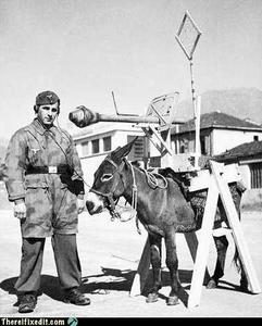
In 1947, the “New York Folklore Quarterly” reported a classic
shaggy-dog story “Murgatroyd the Kluge Maker” then current in
the Armed Forces, in which a “kluge” was a complex and
puzzling artifact with a trivial function. Other sources
report that “kluge” was common Navy slang in the WWII era for
any piece of electronics that worked well on shore but
consistently failed at sea.
However, there is reason to believe this slang use may be a
decade older. Several respondents have connected it to the
brand name of a device called a “Kluge paper feeder” dating
back at least to 1935, an adjunct to mechanical printing
presses. The Kluge feeder was designed before small, cheap
electric motors and control electronics; it relied on a
fiendishly complex assortment of cams, belts, and linkages to
both power and synchronise all its operations from one motive
driveshaft. It was accordingly tempermental, subject to
frequent breakdowns, and devilishly difficult to repair – but
oh, so clever! One traditional folk etymology of “klugen”
makes it the name of a design engineer; in fact, “Kluge” is a
surname in German, and the designer of the Kluge feeder may
well have been the man behind this myth.
TMRC and the MIT hacker culture of the early 1960s seems to
have developed in a milieu that remembered and still used some
WWII military slang (see also foobar). It seems likely that
“kluge” came to MIT via alumni of the many military
electronics projects run in Cambridge during the war (many in
MIT’s venerable Building 20, which housed TMRC until the
building was demolished in 1999).
Source: Jargon File (4.3.1, 29 Jun 2001)
kluge /klooj/ [from the German `klug’, clever; poss. related to Polish
‘klucz’ (a key, a hint, a main point)] 1. n. A Rube Goldberg (or Heath
Robinson) device, whether in hardware or software. 2. n. A clever
programming trick intended to solve a particular nasty case in an
expedient, if not clear, manner. Often used to repair bugs. Often
involves ad-hockery and verges on being a crock. 3. n. Something
that works for the wrong reason. 4. vt. To insert a kluge into a
program. “I’ve kluged this routine to get around that weird bug, but
there’s probably a better way.” 5. [WPI] n. A feature that is
implemented in a rude manner.
Nowadays this term is often encountered in the variant spelling
`kludge’. Reports from old farts are consistent that `kluge’ was the
original spelling, reported around computers as far back as the
mid-1950s and, at that time, used exclusively of _hardware_ kluges. In
1947, the “New York Folklore Quarterly” reported a classic shaggy-dog
story `Murgatroyd the Kluge Maker’ then current in the Armed Forces, in
which a `kluge’ was a complex and puzzling artifact with a trivial
function. Other sources report that `kluge’ was common Navy slang in the
WWII era for any piece of electronics that worked well on shore but
consistently failed at sea.
However, there is reason to believe this slang use may be a decade
older. Several respondents have connected it to the brand name of a
device called a “Kluge paper feeder”, an adjunct to mechanical printing
presses. Legend has it that the Kluge feeder was designed before small,
cheap electric motors and control electronics; it relied on a fiendishly
complex assortment of cams, belts, and linkages to both power and
synchronize all its operations from one motive driveshaft. It was
accordingly temperamental, subject to frequent breakdowns, and
devilishly difficult to repair — but oh, so clever! People who tell
this story also aver that `Kluge’ was the name of a design engineer.
There is in fact a Brandtjen & Kluge Inc., an old family business that
manufactures printing equipment – interestingly, their name is
pronounced /kloo’gee/! Henry Brandtjen, president of the firm, told me
(ESR, 1994) that his company was co-founded by his father and an
engineer named Kluge /kloo’gee/, who built and co-designed the original
Kluge automatic feeder in 1919. Mr. Brandtjen claims, however, that this
was a _simple_ device (with only four cams); he says he has no idea how
the myth of its complexity took hold. Other correspondents differ with
Mr. Brandtjen’s history of the device and his allegation that it was a
simple rather than complex one, but agree that the Kluge automatic
feeder was the most likely source of the folklore.
TMRC and the MIT hacker culture of the early ’60s seems to have
developed in a milieu that remembered and still used some WWII military
slang (see also foobar). It seems likely that `kluge’ came to MIT via
alumni of the many military electronics projects that had been located
in Cambridge (many in MIT’s venerable Building 20, in which TMRC is
also located) during the war.
The variant `kludge’ was apparently popularized by the Datamation
article mentioned above; it was titled “How to Design a Kludge”
(February 1962, pp. 30, 31). This spelling was probably imported from
Great Britain, where kludge has an independent history (though this
fact was largely unknown to hackers on either side of the Atlantic
before a mid-1993 debate in the Usenet group alt.folklore.computers over
the First and Second Edition versions of this entry; everybody used to
think kludge was just a mutation of kluge). It now appears that the
British, having forgotten the etymology of their own `kludge’ when
`kluge’ crossed the Atlantic, repaid the U.S. by lobbing the `kludge’
orthography in the other direction and confusing their American cousins’
spelling!
The result of this history is a tangle. Many younger U.S. hackers
pronounce the word as /klooj/ but spell it, incorrectly for its meaning
and pronunciation, as `kludge’. (Phonetically, consider huge, refuge,
centrifuge, and deluge as opposed to sludge, judge, budge, and fudge.
Whatever its failings in other areas, English spelling is perfectly
consistent about this distinction.) British hackers mostly learned
/kluhj/ orally, use it in a restricted negative sense and are at least
consistent. European hackers have mostly learned the word from written
American sources and tend to pronounce it /kluhj/ but use the wider
American meaning!
Some observers consider this mess appropriate in view of the word’s
meaning.
I hope this further muddies the definitional waters for you 🙂
73,
Kevin. KD5ONS
Our book: “SolderSmoke — Global Adventures in Wireless Electronics” http://soldersmoke.com/book.htm Our coffee mugs, T-Shirts, bumper stickers: http://www.cafepress.com/SolderSmoke Our Book Store: http://astore.amazon.com/contracross-20