
I believe Harold is in Elk Grove California. Is there anyone out there who could help him? If so, please send me an e-mail at soldersmoke@yahoo.com
Bill
I’m a very elderly ex-ham living in Elk Grove and my current project is putting together a World War II military surplus IFF. This requires that I solder cable to small circular connectors and I no longer possesss the eye-hand coordination to do this. Do you jnow of any ham who can help me with this-he or she would be reimburses, of course Thanks for you your help
73s Harold S Meltzer ex W2OZX.
Category: Uncategorised
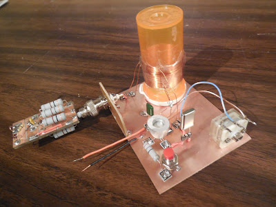
KM4FNQ’s FB Michigan Might Mite

Bill:
transistor: 2n2219a metal can with homemade aluminum heat sink
resistors: 27 ohm 2w 5% metal oxide; 10k ohm 1/4w 5% carbon film
polyvaricon capacitor: from an old am radio 9pf to 149pf
capacitor: 0.047uf polyester film (473)
coil: 1.25in. pill bottle with electric motor magnet wire: 0.017in.
primary: 45t, tap: 15t, secondary: 6t
crystal: hc49/u 3.57 mhz
key: momentary-on switch from radio shack going-out-of-business sale
board: fr4 1oz copper, 3inx4in
pads: me-squares from qrpme.com
dummy load: six 300 ohm 3w metal film resistors
next step: low pass filter.
73 de Ken KM4FNQ
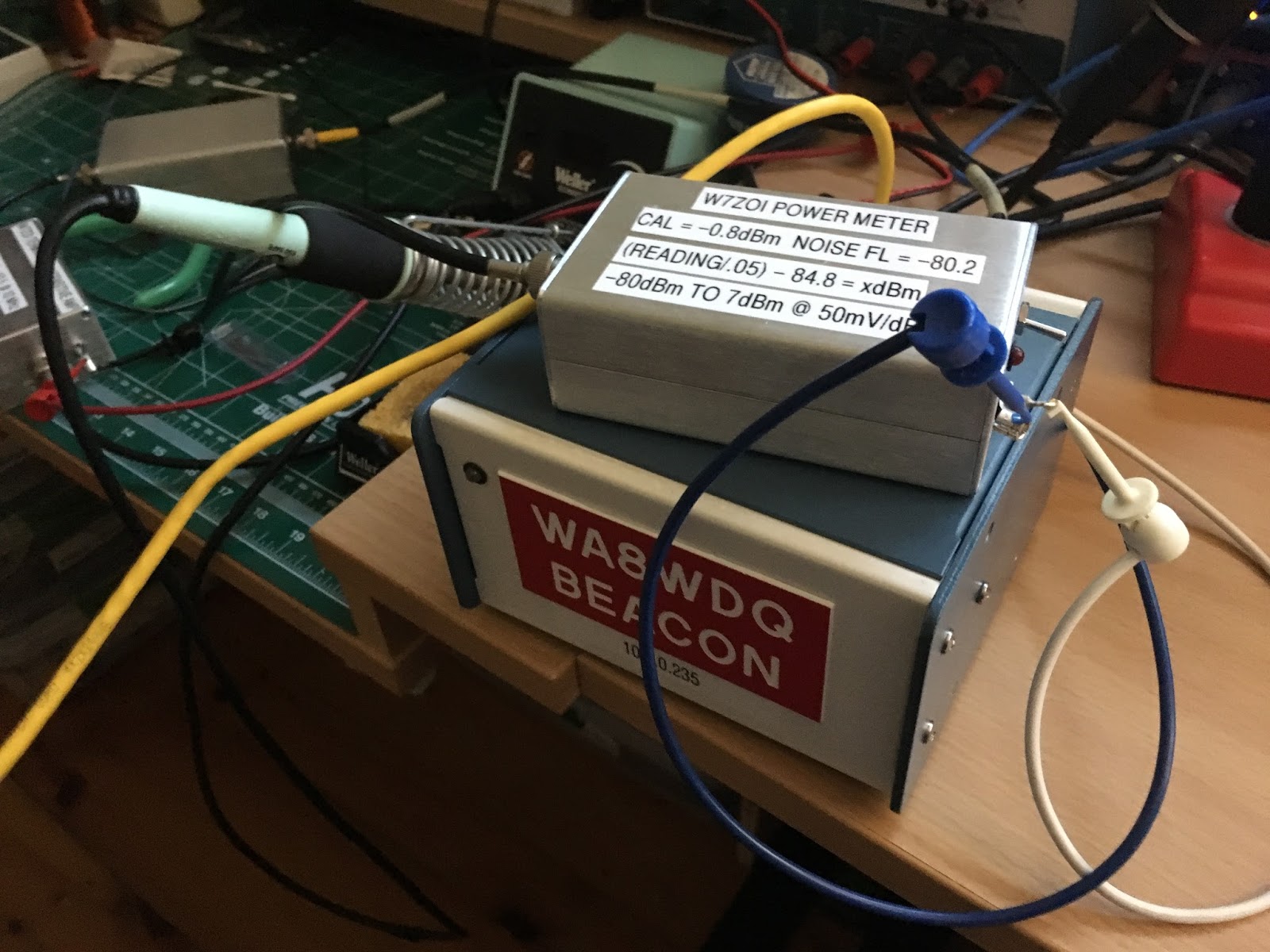
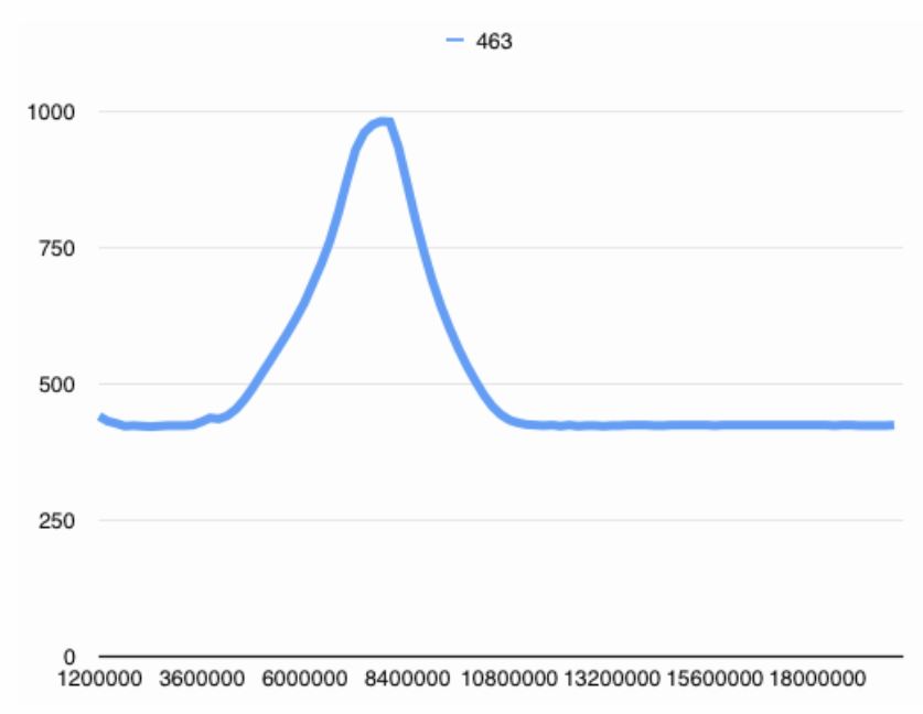
WA8WDQ’s Automated Filter Scanner (and a tip from VK1VXG)
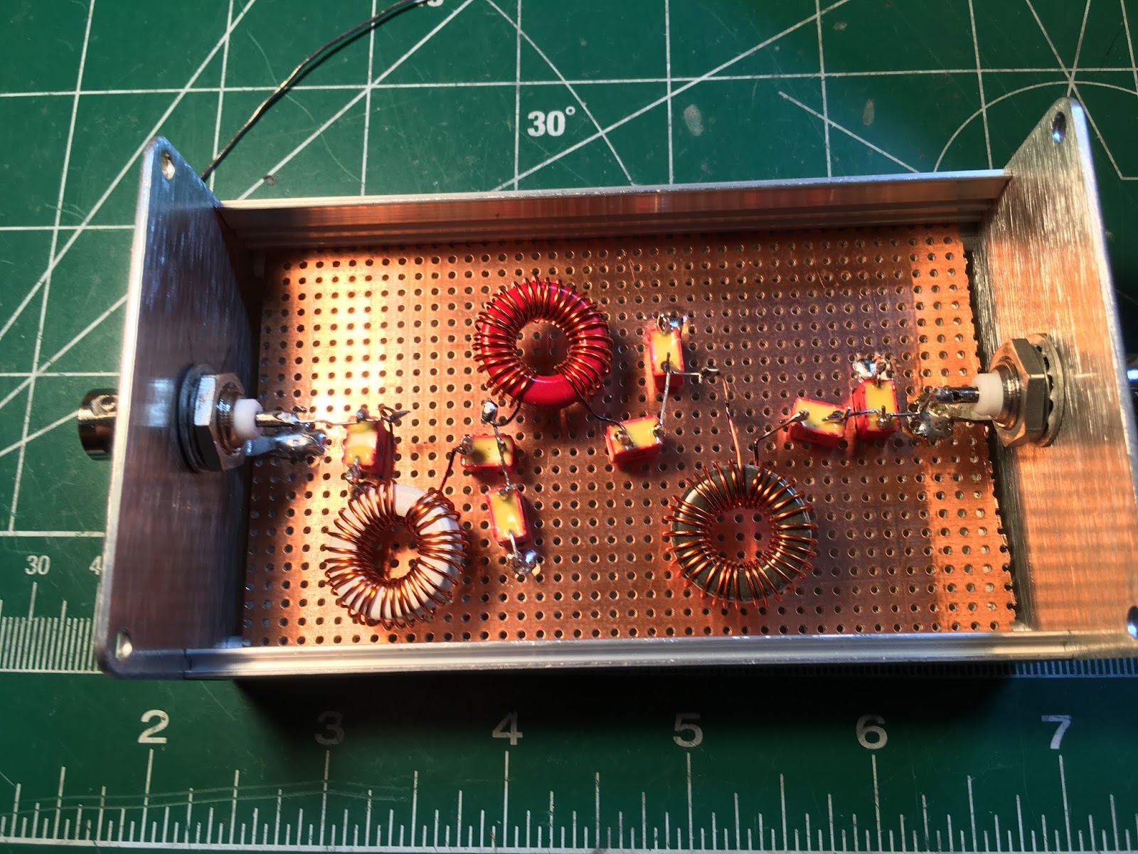
Bill, Pete,
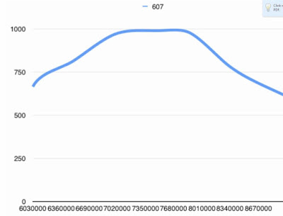
Thought I’d share today’s activities. Using Bill’s excellent wire stripping technique, I was able to finish assembling my 7 MHz bandpass filter. At this point, I’d normally terminate the filter then hook up the signal generator and oscilloscope to manually scan/observe the filter’s response. But today, I took a different tack. Using the AD9851/Arduino signal generator I built last year coupled with the W7ZOI AD8307 Power Meter I built this year, I wrote some additional Arduino code to scan a block of frequencies while using the Arduino’s A/D to record a level at each scanned frequency, thus characterizing the filter’s response. I also used a W7ZOI unidirectional TIA to boost the generator’s output to within the full scale range of the A/D. This setup is similar to the popular PHSNA project that has gained attention over the last couple of years. The Arduino formats the data as CSV then feeds it into Numbers (the Mac Excel equivalent.) for plotting (see attached but please forgive the labels/legend on the plots as I didn’t take the time to format them). Unfortunately, my Arduino UNO is low on RAM so I’m only able to save a max of 100 scanned frequencies. Even with the lack of resolution, as you can see, the output is definitely useable to get a sense of the filter shape and roll-off. I’m now motivated to write some plotting code so I can get a more real-time output in lieu of the spreadsheet. The output of the AD9851 seems pretty flat within several MHz as is the TIA, so the accuracy should be pretty good within moderately sized scan blocks. Adding additional external FLASH (or moving to a bigger Arduino like the Zero) will fix the low resolution. FYI – Arduino behavior when RAM is low can be very erratic! It started crashing when I got close to the max available :(.
If you haven’t as yet, definitely check out the PHSNA project. They’ve added a boat load of features beyond just scanning filter response . . . and at a fraction of the cost of a spectrum analyzer with a tracking generator.
Brad WA8WDQ
Hi Bill,
I’m having trouble posting a comment in response to Brad, WA8WDQ’s
automated Filter scanner project, and I’m hoping you wouldn’t mind
passing this tip along. It might be of use to other readers too.
Recent versions of the Arduino software include a Serial Plotter feature
that lets you graph directly from your arduino. By making use of this
feature Brad wouldn’t need to save data on the uno – just send it back
to the computer and graph in realtime. It is a little primitive, but
still usable. I believe the plot window is 500 datapoints wide.
There is a nice tutorial on how to use it here:
If you’re in a hurry and can survive with a bit of inaccuracy in your
sweep measurement you can also get away with using a simple diode
detector RF probe. This is good enough for a “yep, that filter does
what I want” measurement, but not for measuring exact loss or 3db
bandwidth etc.
Hope that helps,
73s
Greg, VK1VXG
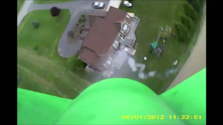
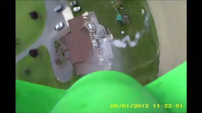
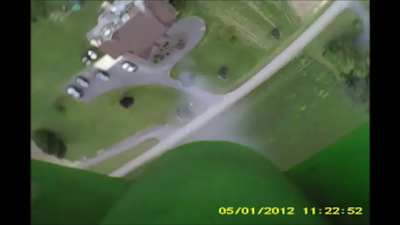
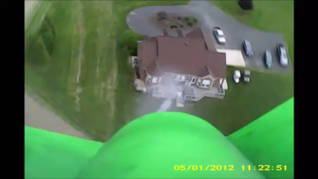
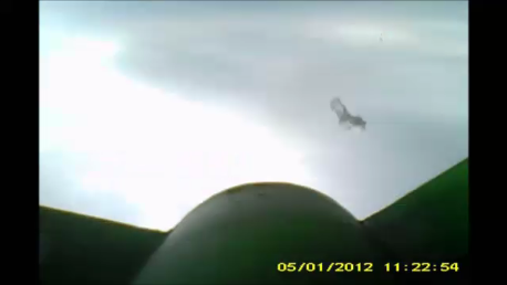
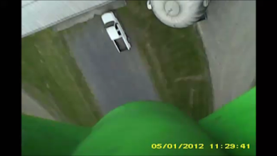
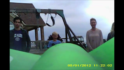
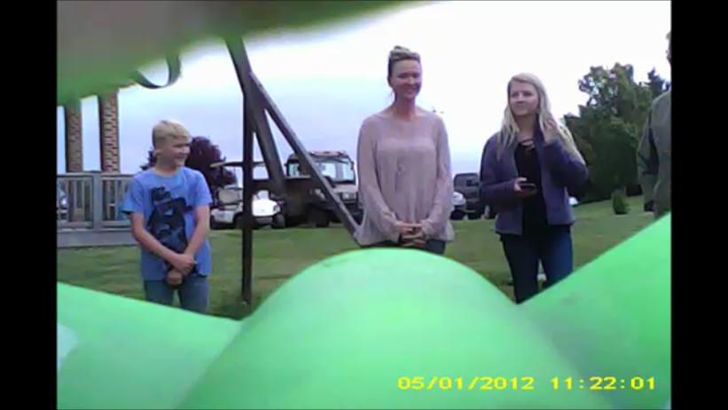
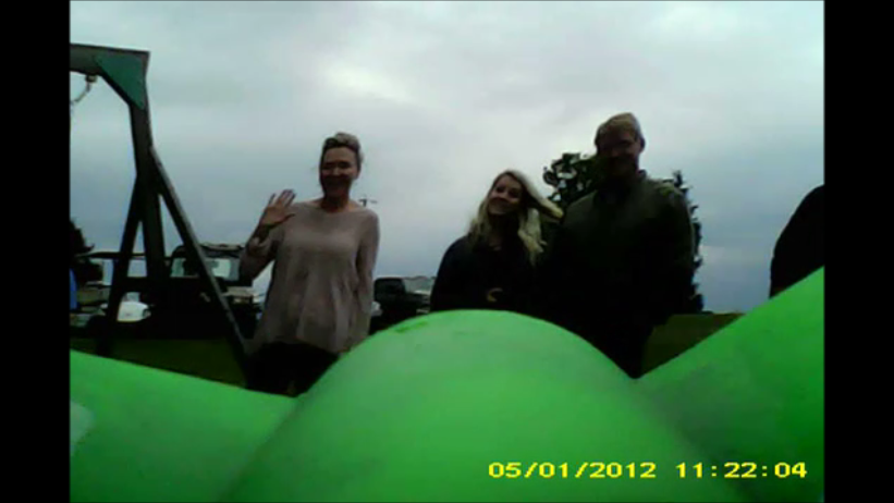
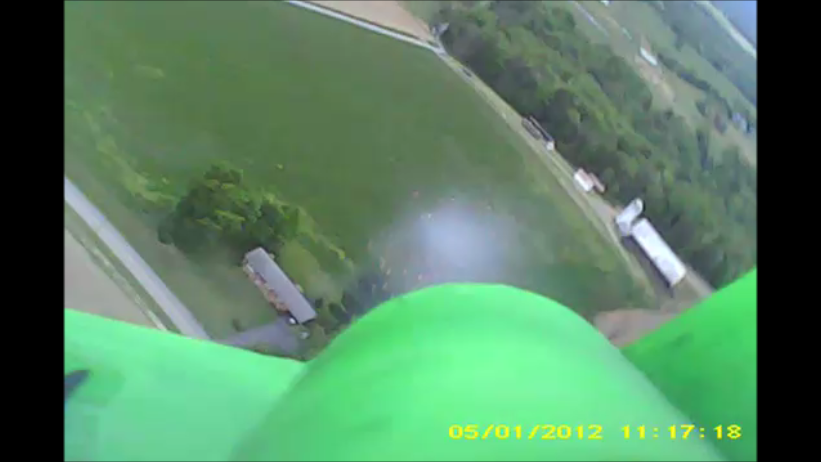
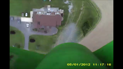
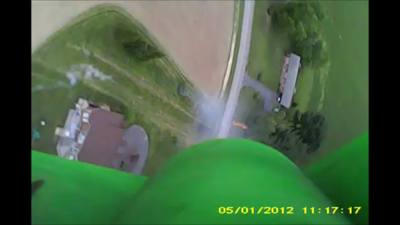
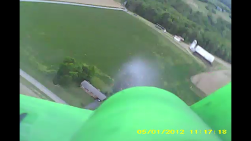
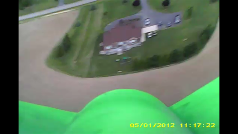
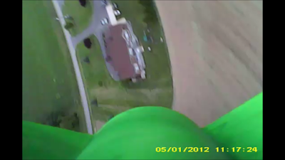
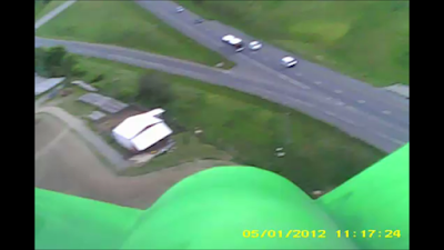
Still Photos and Slow-Motion Video from Shenandoah Rocket Launches
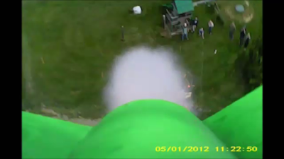
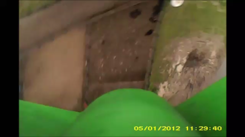
The above slow-motion video of launch #3 is pretty cool. You can very briefly see a bit of the yellow parachute deploying. The best video from this flight is at the end, as the rocket floats over the farm buildings and comes perilously close to landing on top of one of the silos. I put some snap shots at the end. Five other launch videos are available here: https://www.youtube.com/user/M0HBR/videos
SNAP SHOTS
Launch crew visible – N2CQR with hat, Billy to his left. Randy’s son (next to Billy) launches the rocket!
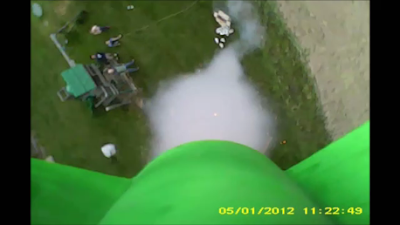
Smoke trail back to the launch pad.
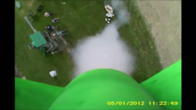
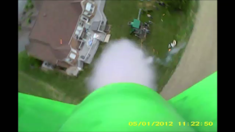
MECO! And you can see the smoke trail up to the rocket
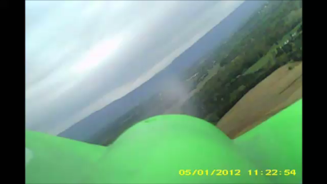
The view across the Shenandoah Valley.
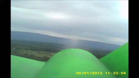
Skyline Drive runs along that ridgeline

Here is a hunk of flame-proof wadding ejected by the rocket.
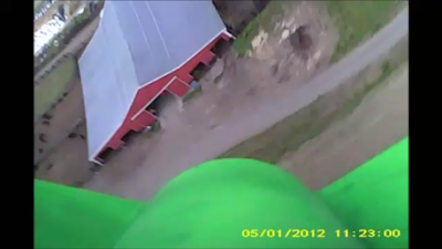
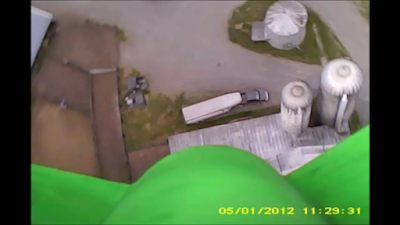
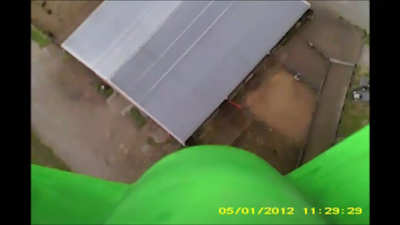
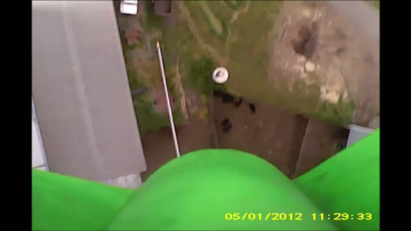
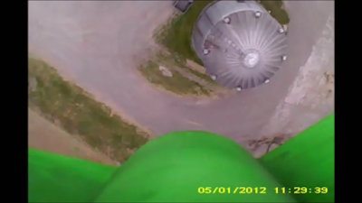
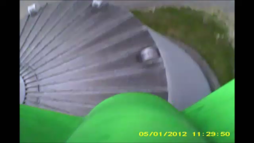
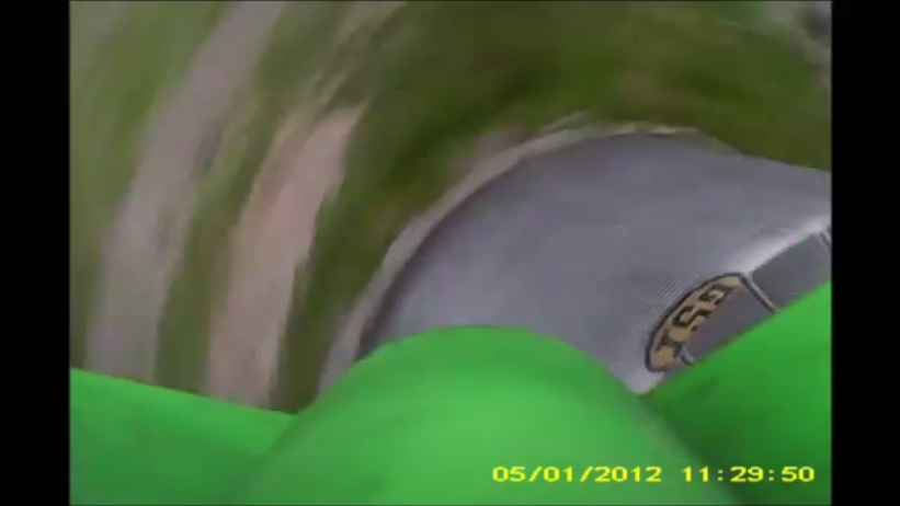
We were afraid it would land on the silo. It was close.
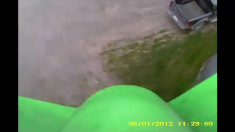
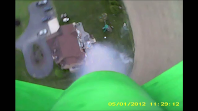
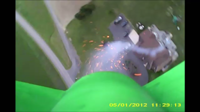
GREAT BALLS OF FIRE! And a smoke trail.
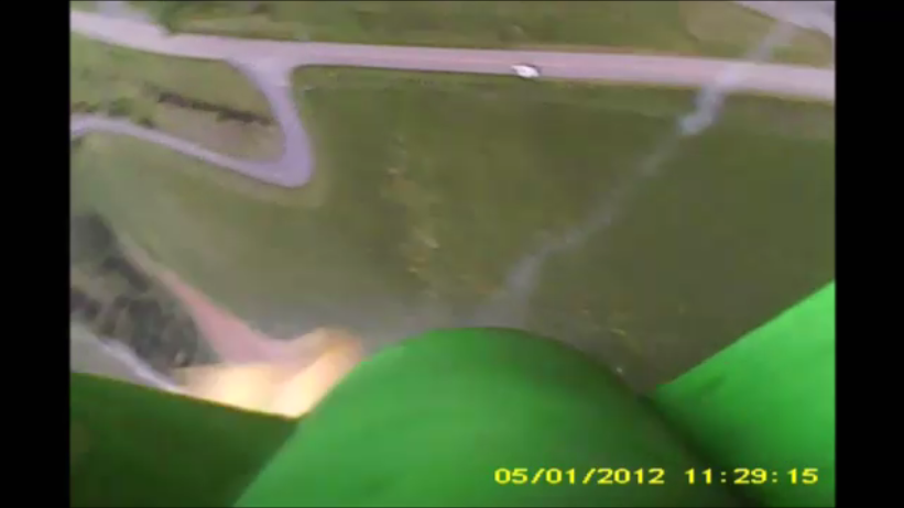
Part of the deploying parachute is visible.
The Hobbyist Guide to RTL-SDR
Lots of good info in this book. I especially like the descriptions of how the useful properties of the dongles were discovered by hobbyists.
https://www.surviveuk.com/wp-content/uploads/2016/07/The-Hobbyists-Guide-To-RTL-SDR-Carl-Laufer.pdf
The Revenge of Analog

40673 LTSpice Model?
Does anyone have an LTSpice Model for the venerable 40673? Or for a similar MOSFET? I’m hoping to find something that I can easily plug into LTSpice.
Hope for 17 Meters? Plasma Bombs! Ionosphere Modification!
But don’t get your hopes up.
Building a Very Stable VFO (With Coils and Capacitors)
As I’ve mentioned, I am building a superhet receiver around the beautiful National Radio gearbox/dial that Armand WA1UQO gave me. First step was to build the VFO. Before I started, I went back to Doug DeMaw’s books and read his words of wisdom on how to build stable VFOs. I followed his advice:
— Air core coils.
— Tuning capacitors with bearings at both ends.
— NPO fixed capacitors.
— All frequency determining parts in a separate box
— Run the oscillator stage at lower voltage (6 volts)
— Stable solid physical construction.
— One-sided PC boards.
I went a bit further. I wound the main coil on a cardboard tube from a coat hanger. I coated it with several layers of clear nail polish. I glued it down with a generous dose of gorilla glue.
There are some fixed caps in the circuit. I didn’t want them physically hanging off other parts, so I used bits of balsa wood to support them.
I put the actual oscillator stage in its own Altoids tin and attached this tin to the bot that held the main coil and capacitor. I put the 6 volt Zener diode and its dropping resistor on the outside of the box to minimize heating. The buffer and amplifier went into another Altoids tin. I used a wooden grilling plank from Whole Foods as my base.
At first, Armand’s gear box and reduction drive didn’t seem wo work very well. There seemed to be a lot of “play” in the mechanism. Some words of wisdom from Pete N6QW and the blog Dave AA7EE provided the solution. There is a spring in the gearbox that hold the teeth of the gears together and prevents the kind of play that I encountered. With guidance from Dave, I was able to put some adiditonal tension on the spring and the gears. This resolved the play problem.
Shotwell had the Knack (Car Knack), and so does Jay Leno
I’ve joked about homebrew cars — we have a bumper sticker on Café Press that says “My Other Car Was Homebrewed From Junkbox Parts.” Well, in this video Jay Leno shows us a true homebrew car, this one built by a 17 year-old in 1931. In the video you will hear some interesting comments from Jay on the kind of technical and mechanical skills that were expected of young men in the 1920s and 30s. At the end of the video, watch Jay suffer the consequences of replacing a 20 amp fuse with an 8 amp fuse. Who among us have not done something similar?
Free Book!

I decided to make my book “Us and Them — An American Family Spends Ten Years with FOREIGNERS” available to a wider audience. The suits at Amazon Kindle allow me to make it available in e-book Kindle form FOR FREE for a five day period starting today. So this would be a good time to put a copy in your Kindle. I think it would be a good book for the beach.
Please spread the word — let friends know of the free book offer.
Here’s the link: https://www.amazon.com/Us-Them-American-Family…/…/B00L8DR4RK
SolderSmoke HQ Station WINS Field Day! Again!

First, I need to make clear that that is NOT me in the picture above. This year I chose to compete as an “E” station: “At home, with the air conditioner on, but using a battery instead of the normal AC poser supply.” This is, of course, only one step from the bottom on the laziness scale — I did hook up the 12 volt gel-cell.
But I made up for it with an unusually large dose Knack-ness. I used my BITX Digi-Zia scratch-built homebrew SSB transceiver. So, with my whopping 11 contacts I feel confident that I won the “1E Homebrew SSB Transceiver, Northern Virginia” category.
Wooden Boats, VFOs and PTOs — Recovering Lost Arts
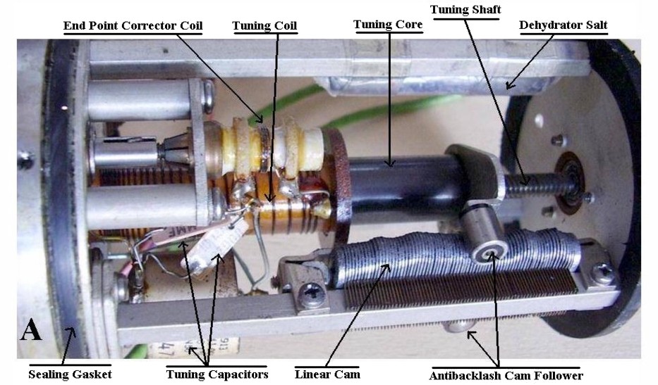 |
| Photo from radiomuseum,org |
I couldn’t resist posting another great message from Rick Campbell, KK7B. This one was sent by Rick to the r2pro mailing list. Rick mentions the Collins Permeability Tuned Oscillator. More info on this magnificent bit of old tech can be found here:
Rick writes:
Great stuff here on different approaches to designing-building-experimenting with stable VFOs. Some of it is a mature art, and some really is a lost art–but that’s good. There’s nothing quite so gratifying as recovering a lost art while taking advantage of modern tools and techniques, and perhaps exchanging ideas on some new-fangled communications medium.
If you ever want to see folks having a blast recovering a lost art, head to a wooden boat festival and watch the kids learning from old codgers who can do magic with a little bit of centuries old technology. Just don’t mistake it for reenactment–some of the new boats these kids are designing, rowing and sailing may include some venerable tools and techniques and give an aesthetic nod to classics, but they are lighter, easier on the environment, easier to transport, and much much faster than historic craft.
We can do the same with our radios. Spend as much time designing and building your VFO as I spent designing the small sailing rig for my little boat–or convert an old Collins PTO to solid state. For highest performance use a mix of old and new–I use hand stitched 1968 sails from the Schatteaur Loft in Seattle on my bigger old boat. Old radios are a treasure trove of parts and technology, and since 1959 well-designed HF gear has been stable enough for SSB.
I measured one of my converted old Collins 2.5 to 3.5 MHz PTOs at 18 Hz per hour drift. It was originally built in the mid 1950s. Some problems were solved long ago, and the techniques and solutions hold up well over time.
As with the kids studying old wooden boat techniques and then taking their new creations out on the Salish sea, it is well worth our time and effort to spend some time studying how our forbears constructed a good VFO a half century ago. It’s not just the schematic: the construction, materials, temperature coefficients…all are important, and the quickest way to come up to speed is to study old stuff that works well.
Good stuff, and have fun with the experiments.
Best Regards,
Rick
My Kind of Math! The Wooden Fourier Transform Machine
fourier analiser from Gymnasiumnovum on Vimeo.
Mixer math with plywood and gears.
http://www.instructables.com/id/Plywood-Math-Machine/
http://hackaday.com/2016/04/11/fourier-machine-mimics-michelson-original-in-plywood/#more-199177
http://hackaday.com/2014/11/18/harmonic-analyzer-mechanical-fourier-computer/
Beautiful BITX17 Presentation by Chris PA3CRX
This is a really amazing presentation on our beloved BITX rigs. This presentation takes the viewer from block diagram to schematic to photos of the actual circuits and throws in great graphics showing spectra and filter curves etc.
There is no sound.
Here is the link in case the embed above doesn’t work:
https://prezi.com/yn2loy4mi0wo/bitx20/
Thanks Chris!
ArduinWoes
Sometimes I really hate those little boards. Well, not so much the board as the IDE. But now that I’ve built at least two rigs with the little beasts in them (Of course, I blame Pete), I have the need to occasionally update or re-load software.
I tried to do just that today. Downloaded the 1.6.7 version of the IDE. All kinds of weird difficulties. The real show stopper is a message that pops up an announced that the IDE comes bundled with Java Runtime, but the bundle is missing or corrupted. No suggestion re what to do…
A visit to the Arduino blog brings no relief. There ARE lots of messages from others suffering from this problem. And acknowledgements from Arduino people that the problem exists. But no solutions. Any suggestions? Or should I just retro-fit LC VFOs or VXOs?
I seem to go through some version of this every time I try to use an Arduino.
73 Bill
Fessenden AM Broadcast, Christmas Eve 1906? Maybe not….

Garrison Keillor mentioned this in his “Writers Almanac” today. That sent me to Google where I found this:
http://www.radioworld.com/article/fessenden-world39s-first-broadcaster/15157
But in any case, Merry Christmas to all!
A Very Unusual Explanation of AM and SSB — What Do You Think?
Wow, I’ve never seen it presented this way. Am I losing it or is this just completely wrong? This comes from this web site:
http://www.dsprelated.com/showarticle/176.php
TRANSMITTED SSB SIGNALS
Before we illustrate SSB demodulation, it’s useful to quickly review the nature of standard double-sideband amplitude modulation (AM) commercial broadcast transmissions that your car radio is designed to receive. In standard AM communication systems, an analog real-valued baseband input signal may have a spectral magnitude, for example, like that shown in Figure 2(a). Such a signal might well be a 4 kHz-wide audio output of a microphone having no spectral energy at DC (zero Hz). This baseband audio signal is multiplied, in the time domain, by a pure-tone carrier to generate what’s called the modulated signal whose spectral magnitude content is given in Figure 2(b).
In this example the carrier frequency is 80 kHz, thus the transmitted AM signal contains pure-tone carrier spectral energy at ±80 kHz. The purpose of a remote AM receiver, then, is to demodulate that transmitted DSB AM signal and generate the baseband signal given in Figure 2(c). The analog demodulated audio signal could then be amplified and routed to a loudspeaker. We note at this point that the two transmitted sidebands, on either side of ±80 kHz, each contain the same audio information.

In an SSB communication system the baseband audio signal modulates a carrier, in what’s called the “upper sideband” (USB) mode of transmission, such that the transmitted analog signal would have the spectrum shown in Figure 3(b). Notice in this scenario, the lower (upper) frequency edge of the baseband signal’s USB (LSB) has been translated in frequency so that it’s located at 80 kHz (-80 kHz). (The phasing method of SSB radio frequency (RF) generation is given in Appendix A.)

The purpose of a remote SSB receiver is to demodulate that transmitted SSB signal, generating the baseband audio signal given in Figure 3(c). The analog demodulated baseband signal can then be amplified and drive a loudspeaker.
In a “lower sideband” (LSB) mode of SSB transmission, the transmitted analog signal would have the spectrum shown in Figure 4(b). In this case, the upper (lower) frequency edge of the baseband signal’s LSB (USB) has been translated in frequency so that it’s located at 80 kHz (-80 kHz). The baseband signal in Figure 4(a) is real-valued, so the positive-frequency portion of its spectrum is the complex conjugate of the negative-frequency portion. Both sidebands contain the same information, and that’s why LSB transmission and USB transmission communicate identical information.
And again, in the LSB mode of transmission, the remote receiver must demodulate that transmitted LSB SSB signal and generate the baseband audio signal given in Figure 4(c).

A Very Unusual Explanation of AM and SSB — What Do You Think?
Wow, I’ve never seen it presented this way. Am I losing it or is this just completely wrong? This comes from this web site:
http://www.dsprelated.com/showarticle/176.php
TRANSMITTED SSB SIGNALS
Before we illustrate SSB demodulation, it’s useful to quickly review the nature of standard double-sideband amplitude modulation (AM) commercial broadcast transmissions that your car radio is designed to receive. In standard AM communication systems, an analog real-valued baseband input signal may have a spectral magnitude, for example, like that shown in Figure 2(a). Such a signal might well be a 4 kHz-wide audio output of a microphone having no spectral energy at DC (zero Hz). This baseband audio signal is multiplied, in the time domain, by a pure-tone carrier to generate what’s called the modulated signal whose spectral magnitude content is given in Figure 2(b).
In this example the carrier frequency is 80 kHz, thus the transmitted AM signal contains pure-tone carrier spectral energy at ±80 kHz. The purpose of a remote AM receiver, then, is to demodulate that transmitted DSB AM signal and generate the baseband signal given in Figure 2(c). The analog demodulated audio signal could then be amplified and routed to a loudspeaker. We note at this point that the two transmitted sidebands, on either side of ±80 kHz, each contain the same audio information.
In an SSB communication system the baseband audio signal modulates a carrier, in what’s called the “upper sideband” (USB) mode of transmission, such that the transmitted analog signal would have the spectrum shown in Figure 3(b). Notice in this scenario, the lower (upper) frequency edge of the baseband signal’s USB (LSB) has been translated in frequency so that it’s located at 80 kHz (-80 kHz). (The phasing method of SSB radio frequency (RF) generation is given in Appendix A.)
The purpose of a remote SSB receiver is to demodulate that transmitted SSB signal, generating the baseband audio signal given in Figure 3(c). The analog demodulated baseband signal can then be amplified and drive a loudspeaker.
In a “lower sideband” (LSB) mode of SSB transmission, the transmitted analog signal would have the spectrum shown in Figure 4(b). In this case, the upper (lower) frequency edge of the baseband signal’s LSB (USB) has been translated in frequency so that it’s located at 80 kHz (-80 kHz). The baseband signal in Figure 4(a) is real-valued, so the positive-frequency portion of its spectrum is the complex conjugate of the negative-frequency portion. Both sidebands contain the same information, and that’s why LSB transmission and USB transmission communicate identical information.
And again, in the LSB mode of transmission, the remote receiver must demodulate that transmitted LSB SSB signal and generate the baseband audio signal given in Figure 4(c).
Gregory Charvat HAS THE KNACK
Gregory Charvat N8ZRY
Yesterday I was talking to Allen W5SQK on 17. He mentioned that he been working in his shop. You don’t hear that too often these days, so naturally I asked what he was working on. Turns out that OM Allen is building a coffee can radar! He is enrolled in the MIT Lincoln Lab’s Open Courseware Project (which looks very cool). We had a great QSO, sharing tales of woe about the release of magic smoke from (dis)integrated circuits. These are the things that pull us together my friends!
On the MIT page the name of a faculty member caught my eye: Dr. Gregory Charvat N8ZRY. Greg’s rigs have been discussed on this blog at least twice, but it wasn’t until today that I became aware of his many other interesting technical activities.
Videos:
Greg’s KNACK STORY: