No More Automatic E-mails from the SolderSmoke Blog

Blogspot and Feedburner tell me that as of the end of August 2021, they will no longer be sending automatic e-mails to those who have subscribed to e-mail alerts for blog postings.

I believe you can still subscribe to the blog. But no more e-mailed alerts.

Please let me know if this loss of automatic e-mails will cause major disruptions for you.

soldersmoke@yahoo.com

Herb Johnson

Hello Bill,

I have been a long time listener and your discussions over the years of the SSB traditions and myths have intrigued me. I have collected most of the editions of the ARRL SSB handbook along with a few others including the 1962 CQ “New Sideband Handbook”. Both the 1962 ARRL edition and the CQ book are at the front of when SSB was just starting to be an interesting “latest new thing” for ham radio. Both have great detail of the technical advantages and show many systems that do both USB and SSB capability on each band. They both have blurbs about how to tune in SSB and also how to know whether you are receiving LSB or USB. What both are totally absent about is the “normal” operation of LSB on 40m and down and USB at 20m and above. Nothing. Not a word of that. That was SSB in 1962.

Now consider the technology and the time. Separate receivers and transmitters were how things were done. But SSB operation requires a LOT of stability of both the receiver and transmitter frequency control to work well. The answer to make SSB work easily for general amateur use was the transceiver and the only real one at that time was the KWM by Collins. Great equipment but outside the budget for many. So the time was right for a disrupter. And your recent mention of Swan is exactly that. It was started in Herb Johnson’s garage in 1962 and the first rigs were single band SSB transceivers (100 series) and well suited for mobile. These rigs also ONLY had LSB for the 80 and 40 versions and USB for 20. When you think about it, there is no technical advantage of LSB vs. USB and in fact, if both are being used, it is a distraction. Imagine doing mobile or a contest and also having to figure out which side band to be on. The military found the answer in the late 50’s by adopting the Collins equipment for the new B52 and only ever using USB. So Swan’s use of this was both a convenience and probably economic. This was the age of “Muntzing”.

Once Swan started to take off, they added the 240 which covered 80, 40 and 20. I have attached the first page of the manual and also a clip from the schematic. The new “normal” was the sidebands as we use now and reverse was an “option”. Bill, you probably had one of the few that actually had this option installed. Later Swan radios actually included the reverse option, but regular was now titled on the front panel of many rigs by then as “normal”. So it is my belief that it was probably Swan that really is responsible for the “standard” operation as we now know. There were others of the time, but Swan was definitely an early leader in economical transceivers and produced over 80,000 during it’s existence.

Now I found in the 1970 edition of the ARRL SSB Manual on page 8 this important final clue. They note that because of some manufacturers only having a single sideband a “species of standardization on the particular sideband used in various amateur bands” had developed. BINGO, you can blame it on the appliance operators!

So our “standard” was well set by the end of the 60’s and was probably wrapped up in operating ease and product economy, and not so much for technical reasons. That is my 2 cents on this.

Enjoy and 73

Dave Wendt

VE3EAC / N9GQ


A Great Line from the FMLA Articles

The narrator was in CW contact on 6 meters with a guy who turns out to be… Frank Jones.

———-
I threw the switch on my AEA keyer and sent the station description while I deciphered my notes. When the keyer signed, Frank said: QSL THE COMMERCIAL GEAR – EVER THINK OF TAKING UP AMATEUR RADIO? QRQ?
———-
More to follow.

The complete FMLA collection can be found here:

TRGHS: K3ZO heard from the Dominican Republic

We arrived in the DR just yesterday, and this morning was my first chance to do some ham radio stuff. I fired up my old Sony SW receiver (the one with the busted BFO fine tuning control) and tuned to 20 meters. The very first station I tuned in (after adjusting the BFO with my Swiss army knife) was talking about the Cicadas. He described weather similar to that which we had just left in Northern Virginia. Then I heard the call: K3ZO. It was Fred Laun up in Maryland! When I first came to the DR in 1992, the locals were talking about Fred as if he had just recently past through. I learned, however, that he had been there during the 1960s! He had left quite an impression. He had saved one of the local hams during the 1965 political violence. I gave that same local ham some Vibroplex parts so that he could fix up an old bug that Fred had left him.

Wow, it was really cool to have Fred Laun be the very first ham I hear during this trip. The Radio Gods Have Spoken. We need to spend more time (especially winter time!) in the DR!

I have a video of this listening session that I will post when we get back to Virginia.

Understanding the Gilbert Cell

I’ve been using the Gilbert Cell (in its NE-602 form) for many years. It was in the G-QRP Sudden Receiver. It was in the Neophyte receiver, it was in that little 20 meter DSB rig that I used in Rome and the Dominican Republic. But truth-be-told, every time I used one I heard Jean Shepherd’s voice in my head, razzing me about the fact that I didn’t really understand how the Gilbert Cell works.

My ignorance was kind of understandable, the Gilbert Cell was built around a circuit rarely used in ham radio: the differential pair. And Gilbert used three of them.

My most recent use of the G Cell came after I watched Mike WU2D’s videos on upconverters for the RTL-SDR Dongle. I had an NE-602 all boarded, boxed and socketed, so I used it in my version of the upconverter. But as I did so, I pledged — this time — to really learn how it works.

So I started cracking the books (and the internet) on the Gilbert Cell. It is a very interesting circuit. Gilbert was working to come up with a double balanced mixer that could be built on a chip without the use of the big toroids that we have in our diode ring mixers.

From my study of other mixers I knew what was needed to get two signals to really mix: You needed a non-linearity. You needed the gain or loss experienced through this non-linearity by one of the signals to be determined by the level of the other signal. If you had this, you’d have at the output a complex repeating wave form. Fourier told us that this kind of waveform has within it a number of sine waves and that among them will be one at the sum frequency of the two waves and one at the difference frequency. That’s mixing in a very small nutshell.

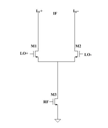
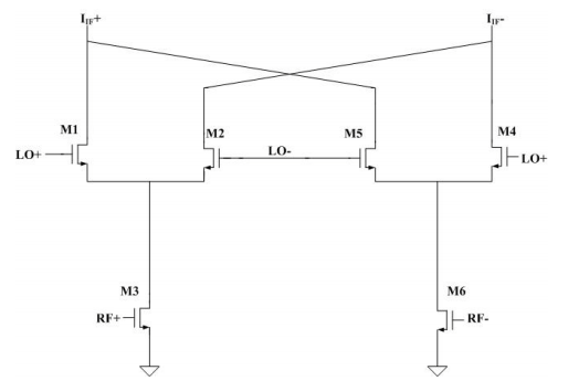
Descriptions of the Gilbert Cell usually begin with single differential pair with a current source controlled by another amplifier connected to the emitters in the two transistors in the differential pair:

The gain of the M1 M2 differential pair will be determined by how much current current is flowing into their emitters. The signal coming into the RF port will control this current. So, assuming there is some nonlinearity in these circuits, RF will mix with LO and at the IF you will have sum and difference frequencies.

The problem is that you will also have the LO signal there. A singly balanced mixer balances out one of the inputs. A doubly balanced mixer balances out both. Gilbert came up with a way of eliminating both input signals without having to use the big inductors that are used in diode mixers.

Perseverance gets to Mars with Parachute and Sky Crane

Perseverance under parachute canopy
Perseverance hanging from rocket-powered Sky Crane.
We had another picture of a spacecraft parachuting to Mars:
It was from the Phoenix lander in 2008:

The Sky Crane picture is also awesome, but having spent some time under canopy, I am especially fond of the parachute photos. Dino KL0S and Kevin AA7YQ know what I’m talking about. And Mike WA6ARA used to design and test parachutes for NASA at the Jet Propulsion Laboratory.

My affinity for parachutes probably predates my jumping. My Estes rockets usually returned to earth by parachute (sometimes they used the more economical “streamers”). And my grandfather had a little kite contraption that would send a parachute up to a kite where the device would hit a cork on the line and release the parachute. He used to attach a dollar bill to the toy parachutist for the kids in the neighborhood. Decades later, my dad got one of these, and we frequently flew it during beach vacations. So I like parachutes.

AIRBORNE!

KLH Model Twenty-One II AF Amplifiers Too Hot. Why?

I’ve been working on this nice old FM receiver that Rogier PA1ZZ sent me. When I first tried it, it sounded terrible. I thought it might have been the speaker, but the speaker is fine. There was clearly something wrong in the AF amplifier. Schematic above. Click on it for a better view.

I ended up replacing the complementary pair of output transistors (Q6 and Q7) . The original had house brand designations — I wasn’t sure what to replace them with, so I just used a TIP29C and a TIP30C. With these transistors in there, the receiver sounds good. But the heat sink on the transistors is getting way too hot. I think the AF amplifier is now pulling about 1.4 amps, which is too much.

Another thing I did: I thought Q4 and Q5 might have been bad, so I replaced them with a 2n3904 and a 2n3906.

Why do you guys think the heat sink is getting so hot? What should I do? The supply on this receiver is 25V DC.

HP8640B Counter Repair — Discretion? Or Valor?

Inspired by BH1RBG, I cracked open the HP8640B to have a look at the counter circuitry. Above is the view that greeted me. That is the main counter board after I pulled it out of its socket. You can see the seven little red LED display modules.

It is not as bad as it looks. In fact, I found the construction and accessibility of the HP8640B to be quite impressive (much better than the Tek 465 with all its flaky plug-in transistors). The manual has good, detailed info on how to get into the various compartments, and even as you work, instructions on which screws to remove or loosen appear on the tops of each RF-tight compartment. Nice. This thing was obviously built with the needs of a future repairman in mind.

Above is that same board flipped over. Again, not as bad as it looks.

Above is board A8A3, the board that I suspect is causing me trouble. When I go through the troubleshooting routines in the manual, I get to the point where they check decimal point position. Everything is fine UNTIL I GET TO 16 MHZ. Then the decimal point is not where it should be and the frequency displayed is very wrong. (This is in the internal mode — the counter works fine with an external signal source). The manual then sends me to Service Sheet 15 which points to possible problems on this A8A3 board, U3, U7 or U6D.

Troubleshooting this will be tough. I do not have the extender board that would allow me to test this A8A3 board with the other counter board raised up above it and operating. BH1RBG noted that getting the extender boards is almost as tough as getting the HP8640B itself.

While it really bugs me (!) to have a part of this device not working properly, I could just leave it as is. The signal generator is working fine, and I could use the external counter input to check the frequency. But this is a real kludge.

What do you folks think? Fix it or leave well enough alone? Discretion or valor? Anyone have an extender board? Any ideas on where the fault might be?

Origins of the NanoVNA

https://groups.io/g/nanovna-users/topic/history/68003005?p=,,,20,0,0,0::recentpostdate%2Fsticky,,,20,2,0,68003005

edy555 is a Ham located in Japan and essentially took an existing idea from a couple of Texas Hams and developed sophisticated software and created a kit for the original NanoVNA and opensourced all of it. https://groups.io/g/nanovna-users/topic/51382131#6796
Look at the files section on the forum where I’ve placed his original (translated) design notes: https://groups.io/g/nanovna-users/files/Miscellaneous/NanoVNA%20design%20notes%20by%20edy555
Gen Hu (hugen), a Ham in China then took edy555’s design and improved on the software and hardware and began selling them as assembled devices on the TaoBao website.
Soon, a pile of copies/clones appeared of hugen’s design.Now, version 1 of the NanoVNA hardware which tops out at 1.5GHz is mature and edy555 & hugen are working with others to design NanoVNA V2 that will go up to 3GHz. In the meantime, another developer created the NanoVNA-F with a larger screen but tops out at 1.2GHz


I think the Texas hams Larry is referring to are Milt Cram (W8NUE) and Kees Talen (K5BCQ) who once offered the AQRP Vector Impedance Analyzer kit. The last time I looked that kit was no longer available.

Which had portions derived from a Project STM32-SDR which was developed by
Charlee Hill W5BAA, John Fisher K5JHF, Milt Cram W8NUE and Dave Miller
VE7PKE/VE7HR. The software was released as open source.
The STM32/SDR project has morphed to the IQ32 which is still in production.
Charlie and Milt over the years have created some wonderful things.

COVID-19 — StayInTheShack (“SITS”) — Our Contribution to Flattening the Curve

Early in the COVID-19 Emergency, I saw this inspiring picture of Dick Dillman W6AWO. Dick had placed a caption under the picture: “I’ve moved to the command bunker and will be staying here for the duration.” That’s the spirit OM! That is what we as radio amateurs should be trying to do at this point. That is how we can help flatten the curve and slow the transmission of the virus.

I guess we could call this #SITS: Stay-In-The-Shack. For many of us this is really not much of a sacrifice — this is what we mostly wanted to do anyway. And we have people to talk to (on the air).

So… Follow OM Dillman’s lead. FLATTEN THE CURVE! STAY IN THE SHACK!

73 and take care.

Some Inspiration from Farhan

As a fresh radio amateur in the 80s, one looked at the complex multiband radios of the day with awe. I remember seeing the Atlas 210x, the Icom 720 and Signal One radios in various friends’ shacks. It was entirely out of one’s realm to imagine building such a general coverage transceiver in the home lab.
Devices are now available readily across the globe through online stores, manufacturers are more forthcoming with their data. Most importantly, online communties like the EMRFD’s Yahoo group, the QRP LABS and BITX20’s groups.io community etc have placed the tribal knowledge within the grasp of far flung builders like I am.


One knows that it was just a matter of breaking down everything into amplifiers, filters, mixers and oscillators, but that is just theory. The practice of bringing a radio to life is a perpetual ambition. The first signal that the sputters through ether, past your mess of wires into your ears and the first signal that leaps out into the space from your hand is stuff of subliminal beauty that is the rare preserve of the homebrewer alone.

Please Listen for My 80 Milliwatt CQ Tomorrow, Wednesday 16 Octoberr

I will be calling CQ from Northern Virginia starting at 1330Z (0930 Eastern) on Wednesday 16 October 2019 on 7038.6 kHz with my ET-2 QRPpp rig. I have made two contacts so far — both contacts were at a range of about 300 miles. I’d like to be able to make at least one per day. If you are within range please listen for my CQ tomorrow and give me a call.

Thanks and 73 Bill N2CQR

Virginia to New Hampshire (one way) on 8 Parts and 20 mW

Having gotten the regen receiver portion of the ET-1 transceiver working nicely, I’m now working on the transmitter. This is a much easier circuit to get going. (Check out the right hand side of the schematic below — that is the transmitter.) I have not made any contacts yet, but yesterday I called CQ on 7050 kHz and watched the Reverse Beacon Network to see if any of the skimmer stations picked me up. Success! W3UA up in New Hampshire received my signals.

I was running about 30 milliwatts to my doublet antenna. The transmitter consists of EIGHT parts. And three of them are the low pass filter.

Next step: Bring the transmitter and receiver together by using the switching scheme that OM Yingling used. The RX and TX will share the same single FET (MPF-102 or J-310) with all three leads from the FET switched from TX to RX. Then I will try for the elusive QSO with a single FET.

More ET-1 related posts here: https://soldersmoke.blogspot.com/search?q=ET-1