G7WKE’s Crystal Tester

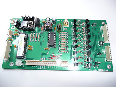
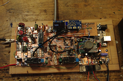
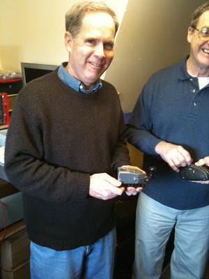
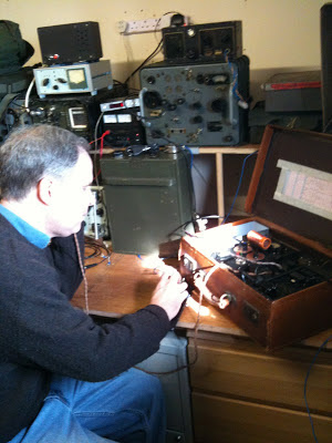
Wow, this is an example of dedication to the cause. I think many of us wimped out when confronted with the complex circuitry of the test device prescribed by DeMaw, but Rob G7WKE actually built the thing, and did a great job on it. I’m tempted to suggest that Rob might want to set up a small business leasing this rig out to less dedicated filter builders. Or perhaps he could have batches of crystals sent to him for DeMaw-ian analysis.

Hi Bill,
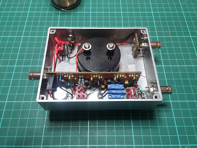
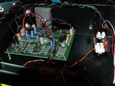
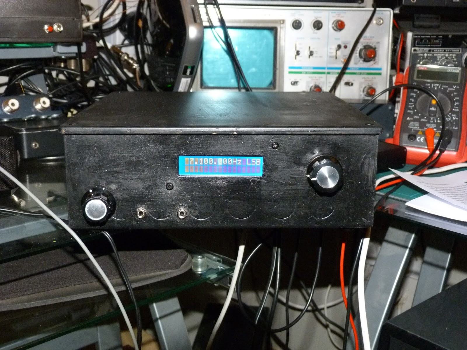
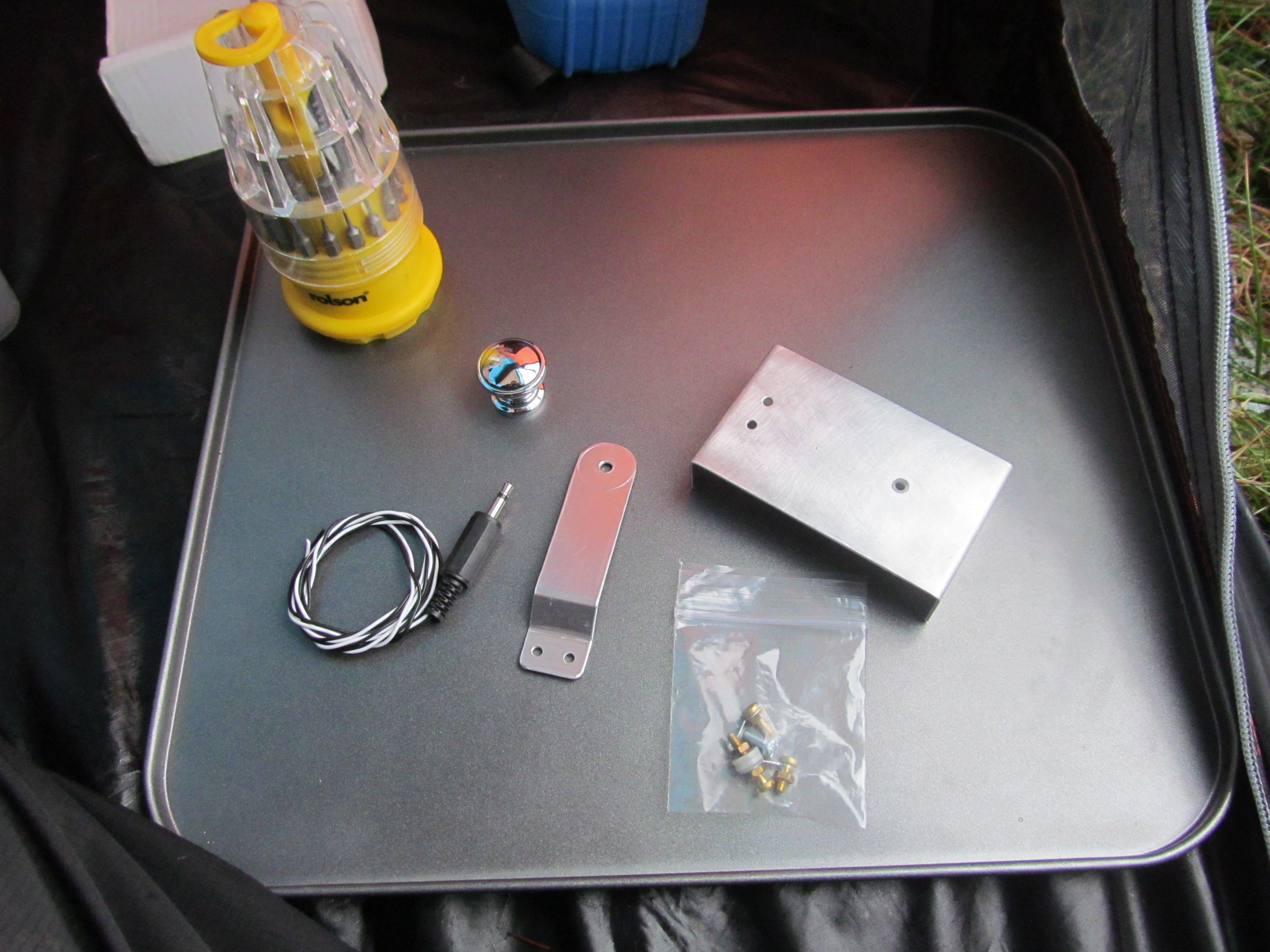
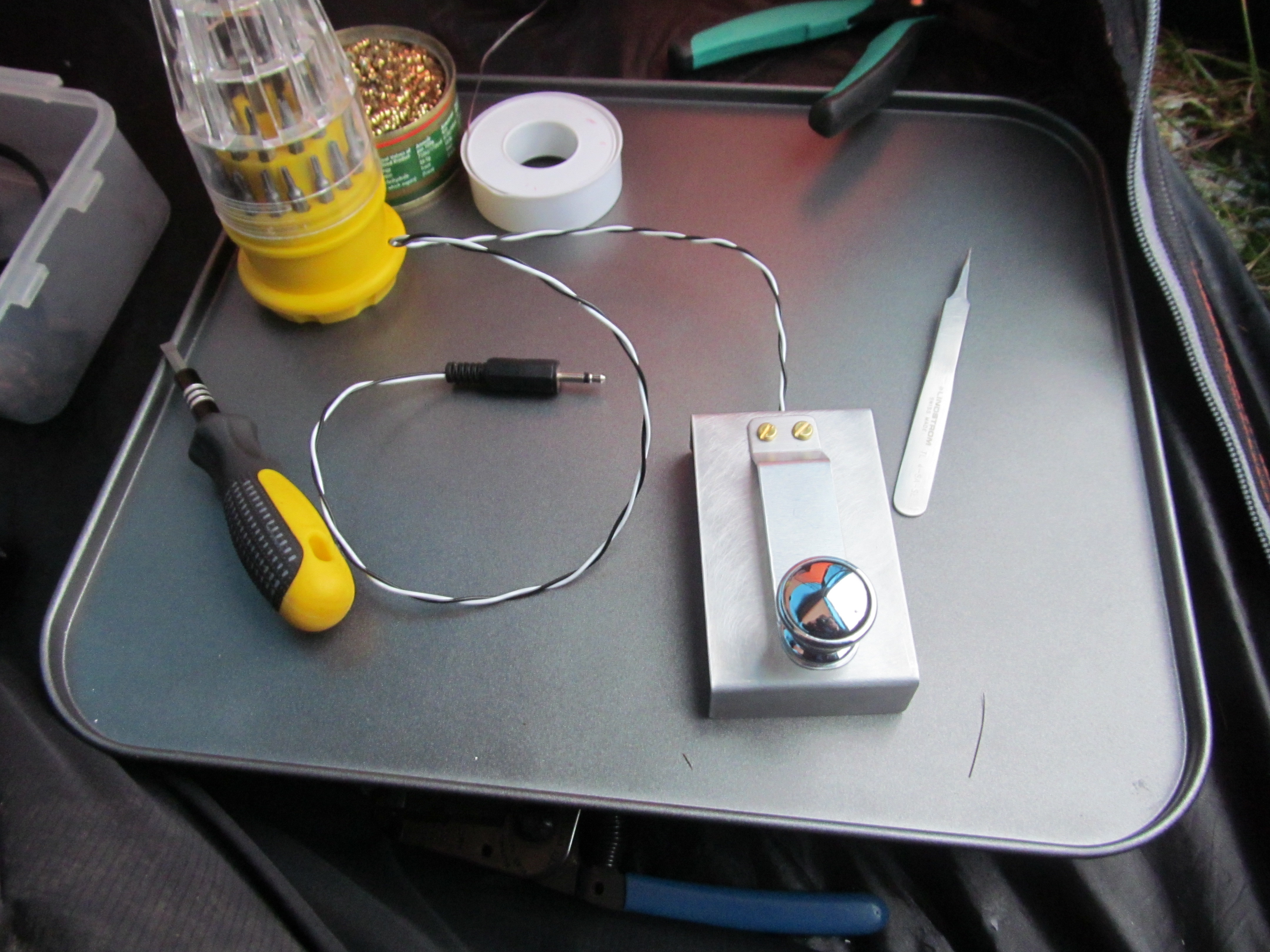
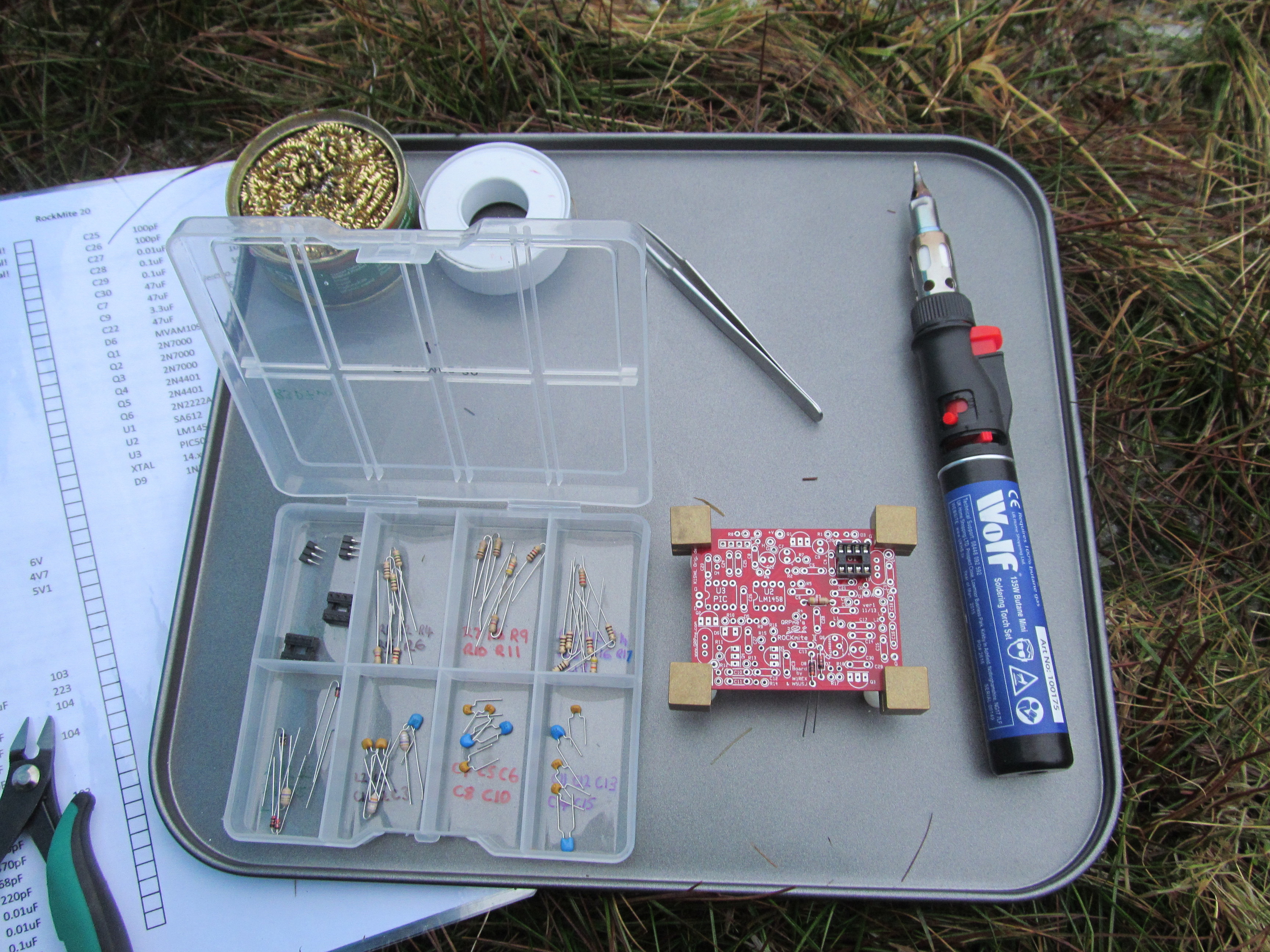
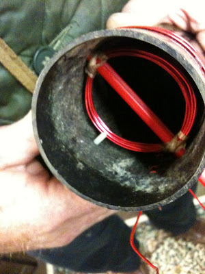
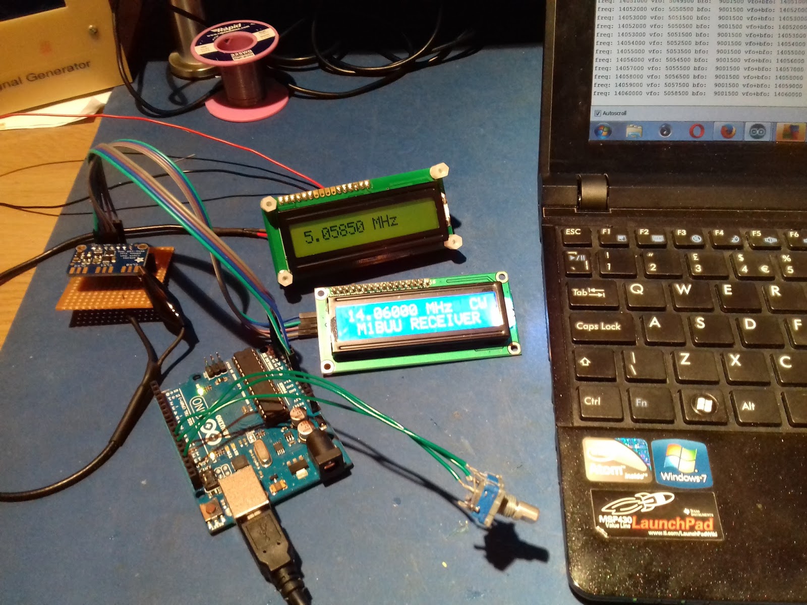
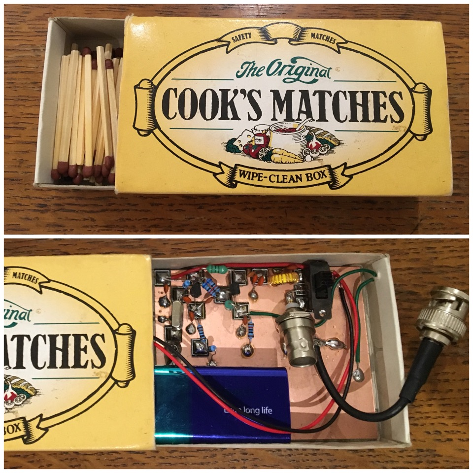
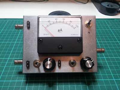
After listening to you and Pete discussing crystal filter design during SolderSmoke 197, I thought you might be interested in my latest project.

This is the Crystal Tester from January 1990 QST that is reprinted in W1FB’s Design Notebook, which I believe is the circuit you and Pete were referring to.

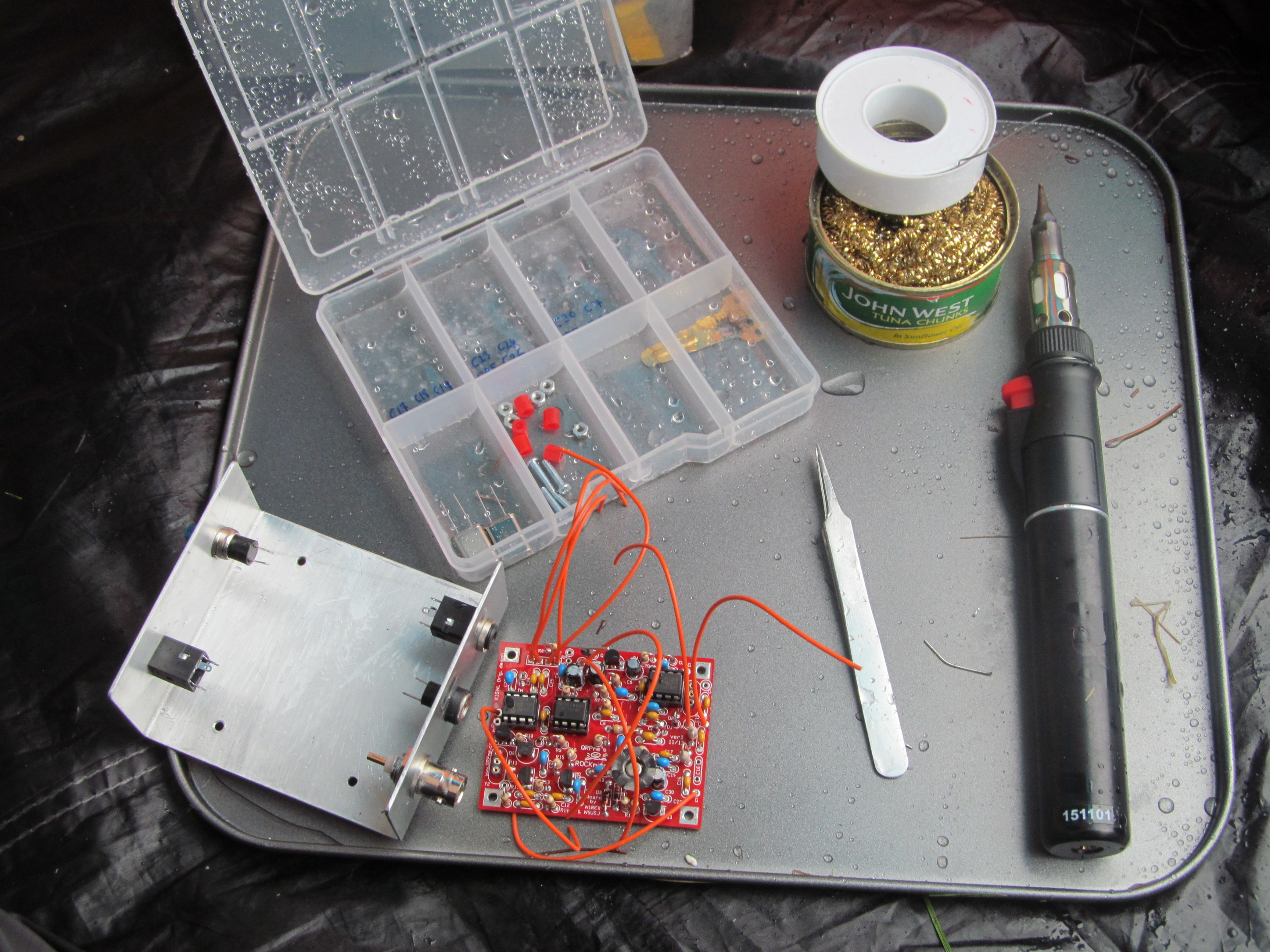
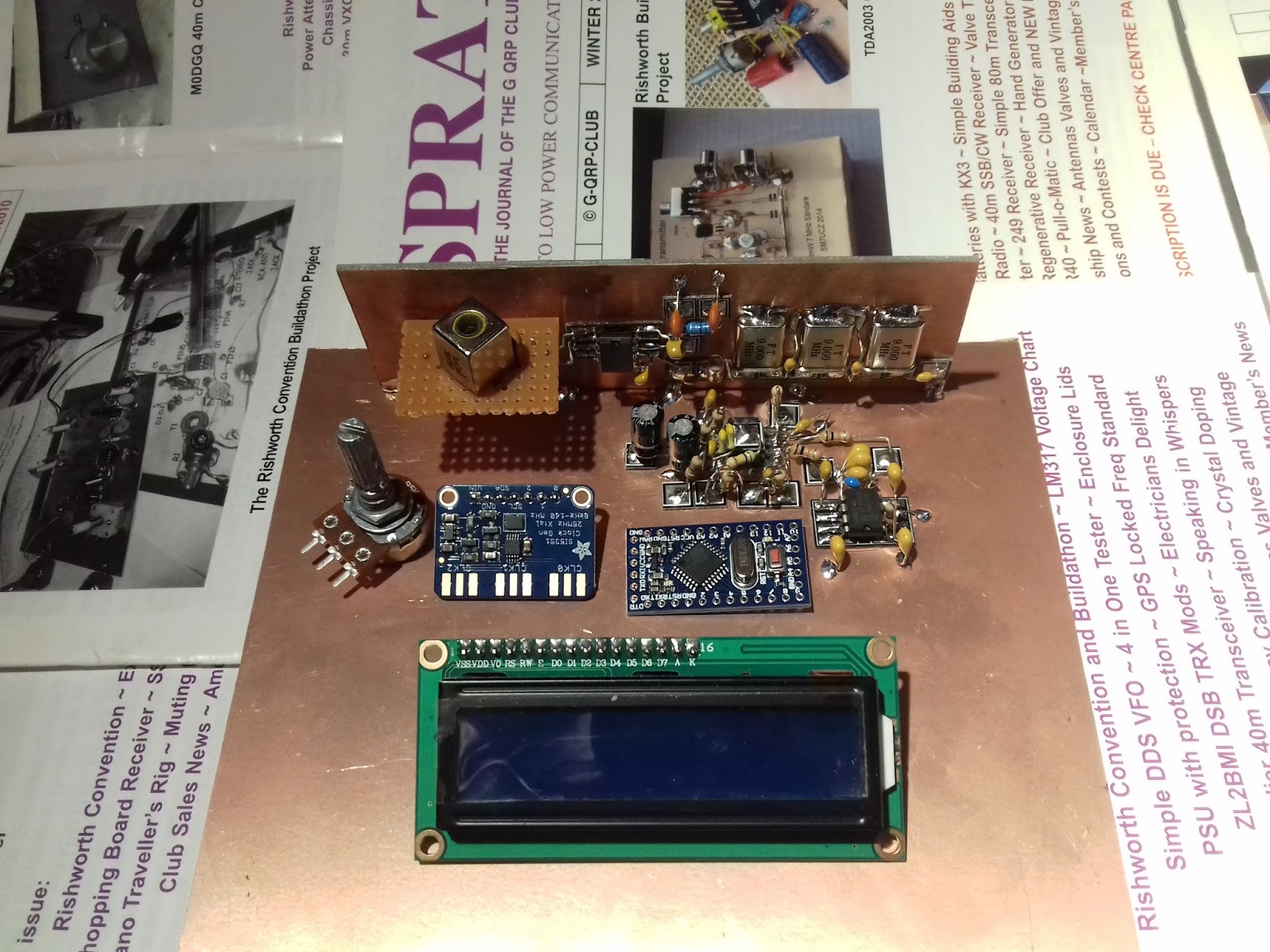
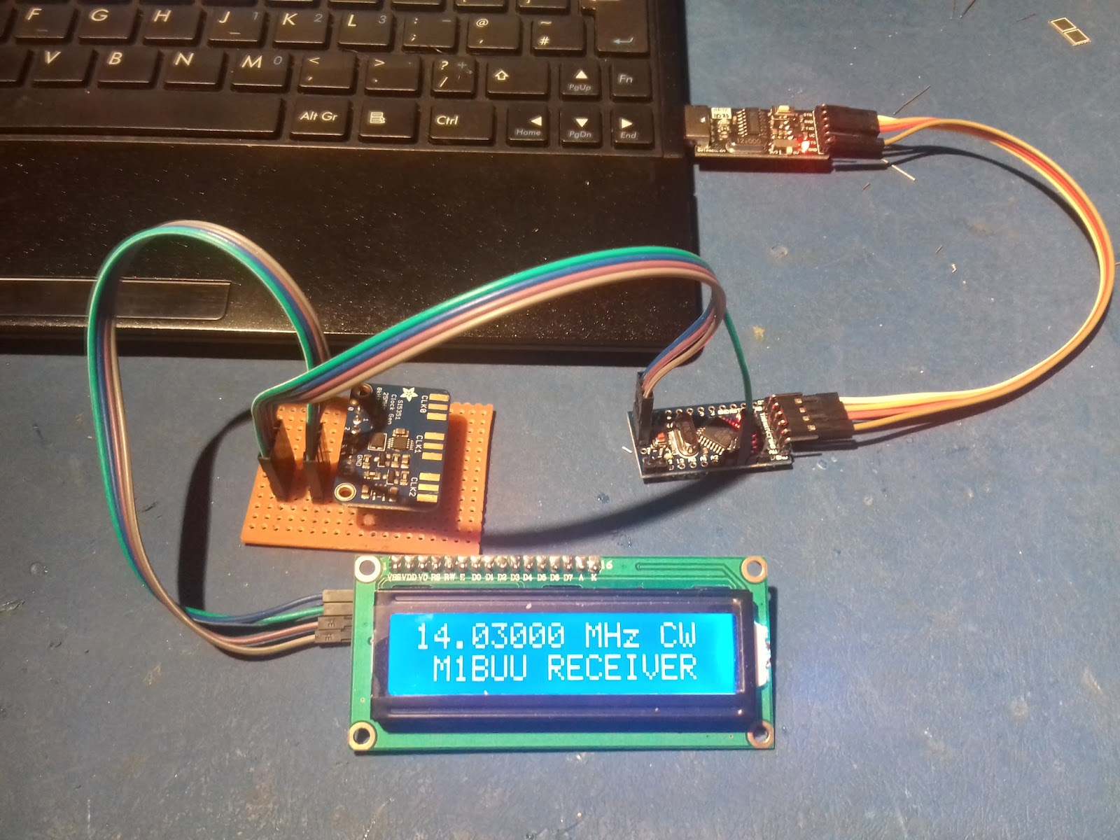
It all appears to function as it should, so the next step is to sit down quietly with a pile of crystals and hopefully start along the road to a working filter!

73s
Rob G7WKE.

Solstice Special: Midwinter BBC Messages to Antarctica


Thanks to SWL Post for alerting us to this wonderful annual event. BBC SW stations send a special program to the UK crews at the Antarctic bases. SWL Posts asks for listeners to record this year’s program:

http://swling.com/blog/2017/06/help-record-the-2017-bbc-antarctic-midwinter-broadcast-today/

Here is an excellent recording of the 2015 show.

https://soundcloud.com/vinylzone/bbc-midwinter-special-transmission-for-antarctica-on-9590khz-21062015-21230z

And here is a recording of the 2017 broadcast:

https://ia601501.us.archive.org/30/items/BBCMidwintersDayBroadcast/BBCWorldService-Antarctic-Midwinters-Day-Broadcast-5985kHz-2130-2200-21-06-2017.mp3

Les Moxon, G6XN

I was on 40 SB tonight talking to Don KC5YR. He is the creator of the web site known as the Moxon Antenna Project: http://www.moxonantennaproject.com/ That site had this great picture of OM Les Moxon, inventor of the wonderful antenna that bears his name. I also found this old QSL card that shows some of Les’s homebrew gear. Les has been a Silent Key for many years now, but his legacy lives on.

WU2D’s Wonderful Video on Retro-QRP

(Link to video appears below.)

Stephen G7VFY sent me the link to Mike WU2D’s Retro-QRP video. In the last month spoken to Mike at least twice on 40 and 75 meter AM. Stephen was responding to a post I did about a 1958 18 milliwatt solid state QRP rig.

Mike’s video is really wonderful. I’ve never been into military surplus, but this video made me think I might want an ARC-5. The rig Mike builds and tests is very similar to our beloved Michigan Mighty Mite. His description of the build and the testing procedures he used will be of great interest to those who’ve built the MMM rigs. And he made some contacts. Finally, there is a cameo appearance by Paris Hilton. And she is holding a HOT transistor! Wow!

Mike has a real talent for making these kinds of videos. Thanks a lot Mike — see you on 40. And thanks Stephen (Stephen has sent us so much great stuff over the years, including a fantastic box of British valves.) Pete: See how nice it is to get back to QRP?

Here’s Mike’s YouTube Channel. I love the intro:
https://www.youtube.com/channel/UCN7RQv_qmzhzuJV1HhJ4OEA

CONFIRMED: Andy G6LBQ Has The Knack (and OTD)


The early fascination with small light bulbs, switches, and batteries confirms the diagnosis. The Ladybird group seems to have led many a young British person down the path to OTD (see the web site for more info on this malady).

https://g6lbq.blogspot.com/

Andy writes:

Hi Bill
I have built a few BitX transceivers and developed a 9 band version which has been built by various hams around the world.
Always look forward to the SolderSmoke podcast which I enjoy immensely.
For your interest I have attached some pictures to show you some of the modules I have designed/developed and built for my Multi-Band projects. The SMD boards are for my latest project which I call the Irwell Transceiver, my intention is to make it all band HF and multimode.
Hopefully my pictures will meet with the SolderSmoke approval and the inauguration can take place for recognition that I officially have The Knack, failing this it will be a Basta moment at the G6LBQ workshop!
Keep up the great work you do with SolderSmoke which brings pleasure, fun and inspiration to hams all over the world.
Kind Regards
Andy de G6LBQ

Ken G4IIB’s BITX Journey

The work of Ken G4IIB has been on this blog before — he helped many of us make use of the amazing RTL-SDR Dongle SDR receivers. He has recently turned his attention to the BITX40 Module and offers some great ideas for testing and for modification. Ken’s description of the smoothness of his audio adds a very evocative term to the SolderSmoke Enhanced SSB lexicon.

Hi Bill, Pete

Many thanks for your respective responses to my plea for help in setting up SI5351 derived BFO to my BITX40 board. You were both on the money.


Pete suggested that I had too much gain in my HB amplifier from the SI5351 output to the modulator and indeed that proved to be true. Once sorted I also noted that I was getting extra hiss on switching to one of the sidebands as you pointed out Bill this proved to be due to incorrect placement of that particular BFO frequency.

These BITX40 boards that Ash Farhan has developed and released to the world wide community of Radio Amateurs are worth every penny. Because they are so hackable (not just the circuitry but now the Raduino code also) it means that you can tailor it to your specific specification and in the process you are likely to learn new stuff and make new friends. I describe my BITX40 incarnation and experiences below:

Upon first firing up the BITX I was getting quite a lot of mains hum from my PSU’s (I thought that at least one of these PSU’s was a quality item) but obviously not up to the job. I constructed a simple one transistor capacitor multiplier (this converted a humble 1000uF cap into a 1F cap) and the noise magically disappeared. By coincidence I note that Bill discussed this technique in a recent pod cast. Another advantage of this technique was that I got a 2V drop across the transistor so by running this on 13.8V I get 12V out so I run the PA section on un-smoothed 13.8V (this gives me 12 watts of RF out) and run the receiver section on the smoothed 12V output from the multiplier, happy days.

My thoughts were to turn my BITX into a multi band (several bands rather than all bands) rig and I figured that using high side mixing (running the VFO at 19Mhz (12Mhz + 7 Mhz) rather than the existing low side mixing (12Mhz – 7Mhz=5Mhz VFO)) would be a better option. For example running it on 17M would mean using high side VFO anyway. I also wanted the ability to be able to switch sidebands especially on the lower frequencies so that I could use the rig for Digital modes in my case this was to be achieved by coding the Arduino to run a BFO on one of the SI5351’s clk ports.

I bought my BITX prior to the release of the Raduino so I had already commenced (with the aid of a new found radio friend and RF mentor) coding an Arduino VFO/BFO using a UNO and SI5351. Like I said at the beginning once you let folk know that you are starting on a new and interesting project you start to engage the more practical members of the ham community and they just want to get involved and help. Yet another good reason to buy a BITX . We used code originally developed by Jason Mildrum NT7S and Przemek Sadowski SQ9NJE and tailored it to suit the BITX40 and our requirements. This include high side VFO with frequency step adjustment and a BFO with long push BFO changeover. This meant that my BITX front panel should stay very minimalistic 2 knobs.
Getting the VFO to work was simple as the DDS socket was used and to better accommodate the high side VFO I modified the board by tombstoning caps C91 & C92.

Getting the BFO to work proved to be more problematic I was troubled with hiss and other noise. Words of wisdom from Pete Juliano when asked if I was doing something wrong were: ” No –it is just that we tend to think our projects are like Lego type building blocks where everything mates and snaps together. Sometimes more is required”. True Pete and that gives us the opportunity to learn new stuff!

To cut a long story short I found that the best place to connect the BFO was on the modulation transformer T4 thus bypassing the BITX BFO stage altogether. I was also getting hash noise believed to be emanating from the Uno. At this stage my after market Raduino arrived from India. I fired this up and noticed that I was not getting any hash noise from it. This pointed us to a coding problem and the LCD refresh was altered on our code and the problem disappeared. Below a picture of the module showing the BFO connections to T4 and the large heat-sink with the IRF510 insulated from it. Also shown is the capacitor multiplier and a glimpse of the Raduino in the foreground. Not the most elegant box but this is likely to change pending further refinements. It’s still work in progress and this box gives me plenty of room.

The Raduino is a fantastic piece of kit for the money extremely neat and well thought out. The coding is comprehensive and innovative and works well. However, from an aesthetic and ergonomic point of view there were a few things that I personally did not like in terms of how it operates and performs. I could not get away with the potentiometer tuning, you can tune 50Khz of the band and then when you near the pot edge it increments/decrements and you can re-tune. I found this clunky to use and in addition the Raduino would hunt causing the last digit to increment then decrement causing an annoying warble on audio. In my opinion a Rotary Encoder would be better solution. On the plus side, although not mentioned on the Hfsigs web site the Raduino code does come with other functions such as changing sidebands by temporary high siding the mixer, a RIT, VFO B and CW tone. If you download and read the Raduino code from Github you will see this extra functionality which I believe you can make use of via extra switches (not supplied). The current Raduino code does not have any external BFO options as said it relies on the crystal BFO and temporally high siding the VFO to change from LSB to USB on 7Mhz.

The Raduino module itself is just too good and neat not to use. As I did not have the where for all to fully understand and amend Ash’s code I decided to use the Raduino but to load it with the code that we have developed for he Uno and Addafruit SI5351 board. This would give me near conventional tuning via a rotary encoder, adjustable step sizes via quick push of the encoder switch and USB/ LSB switching via long push of the encoder switch by virtue of the SI5351 generating the BFO frequency. I have retained a copy of Ash’s Raduino code just in case I wish to revert to it. I put a new header on the Raduino P3 connector so that I could connect a rotary encoder and use the 2nd clock output and then changed our code to run on a Nano. I had to add a correction factor in the code to cater for calibration differences in the SI5351’s (in my case 1.21Khz).

As previously indicated I had a little trouble arriving at the correct BFO frequencies I found that 119940 and 119970 gave me LSB and USB respectively for my high side VFO (19Mhz) if you use low side VFO (5Mhz) then these would be reversed. We further refined these frequencies by injecting white noise into the mic amp and looked at each transmitted sideband on my RTL-SDR dongle via HDSDR (a useful piece of test equipment). By adjusting the carrier trimmer to show the carrier in the extended HDSDR spectrum display we could see how much to move the BFO frequency to best occupy the crystal filter pass band, see image below. This frequency adjustment being achieved by a coding change. The frequencies I consolidated on to cater for my particular crystal filter are 119941 LSB and 119969 USB. We then nulled the carrier back out. My audio is now as smooth as a maiden’s inner thigh, trust me the image will follow!

So now I can get on and build an AGC and think about some sort of S meter. As for putting the BITX on other bands, whilst I now have a VFO capable of going anywhere, I would need to address band pass and low pass filter and switching arrangements. I may still experiment with this but, as pointed out by Ash in a recent pod-cast, the BITX single superhet design is not best suited to multi band operation but can be quite easily changed to operate on another single band. He also indicated that he was developing a dual superhet with consideration for multi band operation. Once released this might be a better option for multi-band use.

In the mean time folk should just get a BITX40, hack it to bits and share with us their customised versions.

Ken G4IIB


Colin M1BUU Achieves SOTA “Mountain Goat” Status — With Rig Built ON THE MOUNTAIN TOP

Stiff upper lip OM! MUSN’T GRUMBLE and all that…

Our friend and BITX builder Colin M1BUU has opened up a new area for ham radio masochism: EXTREME MOUNTAIN-TOP RIG BUILDING. That’s right my friends. You read that right. Colin has taken the solder smoke to new heights. Soon, these guys will be pouring scorn on those of us using “shack built” rigs. Congratulations Colin! Well done!

Colin’s write up from http://reflector.sota.org.uk/t/colin-m1buu-mountain-goat/14559 :

The general story goes something like this –
I started with SOTA way back in 2004, aged 24. Just after I found SOTA, I also found love – Fiona and I will celebrate our 10th wedding anniversary in April. You know how the story goes……….
Winter time has generally been quiet in terms of family stuff, so it’s generally this time of year when I activate, usually January to March.
You’ve heard of extreme ironing, right?


Being a prolific builder of radio kits, I thought I would do my own twist on Extreme Ironing – Extreme Solder Ironing!
Today was the day. I took a RockMite kit, a home made key kit and a home made vertical antenna kit up to the summit of Whernside G/NP-004. I assembled the kits using a gas powered soldering iron. Thankfully I took my little tent with me, the weather wasn’t exactly tropical.
The kits went together well and the RockMite fired up first time without any debugging, although the building took much longer than I had reckoned.
I was late on air, but eventually Barry N1EU found me for my first contact. Shortly after followed SP9AMH, OH9XX and finally EU2MM to earn me my needed points. Mountain Goat was in the bag! The QSB was very evident today, QSO’s were tough, except with OH9XX, who was ear blasting. :smile:
Firing up the FT817 (I intended to share my success with as many as possible!), I worked a handful more stations on CW and SSB, but my time was rapidly dwindling.

Finally, I’d like to say thanks for all the support given by numerous SOTA participants over the years, There’s a number of great, inspirational people we’ve lost in that time and I think about lots of them all the time. Roger G4OWG was particularly on my mind today as I learned of the route I took today from one of his posts. I never met Roger in person, but he was a keen chaser and fairly local to me.
73, Colin
Edit – I forgot to put forward my thanks –
Thanks to Dennis G6YBC (Kanga Products) for sponsoring a RockMite ][ ver. 1 PCB
Also thanks to Pete G4ISJ for supplying the solder!

SolderSmoke Podcast #193: BITX 40, OLEDs, KWM-4, Noise Abatement

SolderSmoke 193 28 Jan 2017


Report from Pete on BITX 40 Session with California radio club.

Update on the BITX40 Module Revolution
— Check out the BITXHACKS page. Send in contributions.
— BITX20 mailing list very active.
— Raduino!
— Interview with Farhan with W5KUB — Eliminating the commercial gear.
— BITX 40s on the beach in Australia. FB

Bench Reports:

Pete:
— Color Displays!
— KWM-4
— OLED MADNESS!

Bill:
— Fixing up the old HT-37 HT37 to HT37 QSO with W1ZB
— Dabbling in VHF with Ramsey Aircraft band receiver. NOT FUN.
— Going all IC with Si5351 OLED NE602 rig.
— BANDSWEEP
— OLED Noise and the Active Decoupling solution.

Using LTSPICE as a diagnostic or understanding tool.

Of Waterfalls, Homebrew Rigs and Casual Critics on 40 meters. Words of Wisdom from W8JI.

LEXICON: HAYWIRE TOMBSTONE BIKESHEDDING from Todd K7TFC

Some great recent interviews by Eric 4Z1UG:
Ian G3ROO Origins of ROO Regen at age 8
Hans Summers G0UPL Balloons! NO COMMECIAL GEAR
David White WN5Y ELECTROLUMINESCENT RECEIVER EXPLAINED
Rob Sherwood NC0B

MAILBAG:

Chris KD4PBJ’s BITX 40 with improved stability
Jerry W0PWE built a DIGITIA! Very nice. Worked Keith N6ORS and heard me! TRGHS
Mike AB1YK’s Al Fresco Scratch built BITX. But give that LC VFO another chance Mike!
Steve N8NM 30 meter rig with salvaged CB LC VFO. FB
Keith N6ORS Franken SDR rig with parts from the 1980s. FB
SKN Bandscan from Mike WA6ARA I worked W1PID Jim!
What is Mikele up to?
Rocking Johannesburg and Kirghizstan via local repeaters:


Wonderful “QSO Today” Interview with Ian Keyser G3ROO

N2CQR and G3ROO
I knew it was going to be a good Sunday morning in the shack when I saw that Eric 4Z1UG had posted an interview with Ian Keyser G3ROO. This wonderful interview brought back memories of my visit to G3ROO’s amazing facility in Dover. (Thanks to Tony Fishpool who brought me out there.)

In this interview, you will hear Ian state — in a very nonchalant English way — that he built his first receiver at age 8. And I really loved the story of how Ian got his call sign. FB Ian.

Ian is a very prominent member of the G-QRP club. I was oddly relieved to learn that he is working on a LEGAL LIMIT LINEAR AMPLIFIER. I hope he has special dispensation from Rev. George Dobbs. I intend to cite this project if we ever have to defend Pete Juliano from charges of QROism.

Listen to the interview here:


That is a key designed for use aboard a hydrogen balloon. This is the kind of thing that Ian has in his shack.

This is Ian’s variometer — mentioned in the interview.

That’s me using one of Ian’s spy sets.
Ian’s antenna book:
Here are the SolderSmoke Daily News posts about Ian and the Dover Construction Club:


Christmas Present! 4Z1UG’s Interview with Han Summers G0UPL

I found myself almost cheering out loud as I listened to this wonderful interview, especially at the point where Hans lets it be known that he has NO COMMERCIAL HAM GEAR in his shack! Yes! That’s the ticket! You can also hear the story of Hans and Farhan meeting up in Mumbai for dinner. The interview includes discussion of WSPR and QRSS and BITX and crystal ovens and, at the end, a special QSO TODAY overtime session in which Hans describes the little WSPR rigs that fly around the world, carried aloft by half-filled birthday party balloons.

Thanks to Eric 4Z1UG and Hans G0UPL for this very nice Christmas present.

Listen here:

http://www.qsotoday.com/podcasts/g0upl

Colin M1BUU’s New Receiver Project


Hi Pete,
Just checking in 🙂
I have actually been melting solder recently. I decided to build a little CW receiver. I love my regenerative RX that I built as a teenager, but after all these years, I’m tired of constantly tweaking the controls!
My project is a 20m CW only superhet receiver with a 9MHz home brew filter. I’m using the SI5351 for the oscillators. I originally thought I would cover multiple bands, but for now I have the parts for 20m coverage. I might tinker with other bands at a later point.
I’m using your LBS code on the Arduino, the one for 20m with 9MHz IF. I haven’t applied power to the rig yet but it’s not far off fully built. I tweaked the Arduino sketch using my Uno and tonight I have successfully transferred the code to a Pro Mini. (Code went into Pro Mini on first attempt – amazing!).
73 for now,
Colin M1BUU


From the Wizard of Wimbledon: Matchbox Junkbox Rig

Dear Bill


I hope that life’s treating you kindly over the left side of the pond. Your latest podcast really resonated with me as I’m hugely fond of junk box projects on a rainy afternoon. Fortunately Her Majesty’s weather men are generous…

Spy gadgets have long been a fascination of mine, particularly those disguised as harmless everyday objects. I remembered a Soldersmoke blog post a few months back showing a radio hidden inside a book. That got me thinking… then one rainy afternoon I stumbled across a half-used box of matches – surely an ideal enclosure for a covert spy transmitter!

Objectives:

1. The matchbox should remain fully functional and pass casual inspection
2. Transmitter, Morse key and battery should be hidden within the box
3. All parts should be cobbled-together from what I can find around the house
4. To build using “Manhattan style” construction for the first time

The transmitter borrows heavily from the Pixie 2 circuit and is based around two PN2222A transistors: the first forms a Colpitts oscillator for 7030kHz (plus/minus a smidgen of capacitor trim), the second acts as a modest Class C power amplifier (approximately 170mW out) – keying occurs here, to minimise chirp, before feeding a simple low-pass filter.

Discrete contacts set in the cardboard allow Morse to be keyed with my grandmother’s old sewing thimble – not only is this beautifully stealthy but it’s remarkably ergonomic too!


The transmitter can be easily teamed with an external receiver, selectable via a double-pole-double-throw switch. The switch simultaneously disconnects the battery, eliminating the audible whistle from the constantly-running oscillator.


This was my first experiment with “Manhattan style” construction and I can see why you swear by it. Even though I sketched the circuit’s layout before I started, I still found myself occasionally popping-off a square with a blade so as to optimise the tight packaging; Manhattan made this trivial, and fault-finding would have been easy with all connections on one side…

But remarkably the transmitter worked first time! Bench testing by calling CQ whilst monitoring the Reverse Beacon Network demonstrated that its tiny signal could be picked up as far away as northern France when driving my resonant end-fed antenna!

Ever since I discovered the magic of QSL cards I have always wanted to send one showing a hand-drawn diagram of my transmitter; perhaps I’ll now have a chance!

Please keep up the great work: you, Pete and the global brotherhood never cease to throw up new tricks for me to try. It’s a shame that this is perhaps one radio which I’d be best advised to not try to carry through airport security when my ever-patient girlfriend grants me permission for a holiday-time QRP operation…

73

Jonathan
M0JGH
——————————–

GW4ZUA’s “Let’s Build Something” Receiver

The LBS project of Pete and Ben continues to inspire homebrewers all around the world. Check out the video of GW4ZUA’s version. Peter GW4ZUA writes:

Hi Pete,

Thank you for your kind words,

I suppose it started with a knob and a pointer to know (guess) where you were on the band, probably most radio builders did the same, and some still do, but as long as it worked you were very satisfied, what a marvelous feeling when you switch on and those electronic components do their job and deliver the goods……amazing.

So time moves on you get better at building and technology gives you a hand, LCD displays, homebrew frequency counters,cheap components, wow now you Know where you are on the band.

Then I saw your rig with a colour display and DDS “I gotta get me one of these.”

I watched most of your videos, Your “easy going, down to earth manner” made it look easy to do.
I love the internet, without it I’d probably still be using knobs and pointers, there are is a wealth of knowledge available to those lucky enough to have access. I also love email, as you can now contact people who are willing to share their projects and give advice.

So the LBS well it certainly works, so few parts but they are all eager to please, with the display (did I mention the display) it is a project you can be proud of.

A big thank you to you and Ben for the project,

I don’t know if it will ever go in a box as I just love to look at it and I’m amazed at what comes out of the speaker.

Regards to you all……….
73’s for now. ………..Peter (GW4ZUA)
————————

As is well known, I’m more of a knob and pointer guy myself, but I understand the attractions and advantages of the glowing numerals. And I definitely sympathize with Peter’s comment about the beauty of an in-boxed rig.

Listen to Keith Ranger G0KJK on “QSO Today”

http://www.qsotoday.com/podcasts/g0kjk

Wow Eric,

I just listened to all of the Keith Ranger interview and was struck by the eerie parallels between YOUR 24 September podcast and OUR 24 September SolderSmoke podcast:

— Both shows discussed the involvement of Anglican clergy in the hobby.

— Both discussed the joys of simple QRP gear.

— George Dobbs G3RJV came up in both.

— BOTH featured discussion of the BD139 transistor (!!!)

— Both discussed the use of ceramic resonators in ham circuits.

Great minds think alike!

I really enjoyed your interview with Keith. I have enjoyed reading in SPRAT about his projects — years ago I built his MB4 receiver. I listened while I worked on my homebrew receiver. It was the ideal accompaniment. I also like the stickers on his transmitter.

Please pass this on to Keith if you can.
Thanks and 73 Bill

———————

I also liked Keith’s comments on the joys and perils of amateur electronic engineering.

In Search of the Elusive Imperial Whitworth

This beautiful old variable capacitor came out of a 1930’s British regen receiver that I picked up years ago at the Kempton Park rally near London. When I rebuilt that receiver, I found that the cap was thoroughly stuck. No amount of solvents could loosen it. I put it in the junk box and used a more modern cap in its place.

When planning for my current BIG VFO project (see yesterday’s post) I re-read Frank Harris’s chapter on VFOs. Frank recommended a non-linear cap — actually a cap that maintains a constant percentage change in capacitance as it goes through its tuning range. My old British cap seemed to fill the bill. Also, it appears to be brass or bronze which is said to have better temperature stability. So I pulled the Brit cap out of the junk box. It was still stuck, but as I tugged on it a bit, it suddenly loosened up. Wow! TRGHS.

When I tried to mount the capacitor in the QF-1 box, I discovered another problem: the nut for the main mounting screw was missing. And guess what: None of the nuts in my “big box of screws and nuts” (I know you guys all have one of these boxes) was the right size. Or, as Pete put it, all were of two sizes: a bit too big, or a bit too small.

Dex ZL2DEX informed me that the needed nut was likely an “Imperial Whitworth” (Don’t you love British names?). I started to think about how to get such an elusive part…. I thought about walking into Home Depot and asking them where they keep their Imperial Whitworths. This wouldn’t have been productive.
Then I started to wonder where the original nut went. It would have stood out in my junk box because it is brass-colored. I looked again in the junkbox. No luck. Then I realized that I might have used it to mount that replacement cap in my rebuild of the old British regen. I pulled that old beast (wooden chassis!) off the shelf. There it was, the needed brass nut. Cap and nut were reunited, problem solved.
It is kind of fun to include an old part like this in the new project.
Thanks Dex. And thanks again to Frank Harris for the great book.