Tim Hunkin on Drilling Holes (Secret Life of Components Video)

I guess that aside from being a great video, this is something of a test of technical nerdy-ism. If you find this hour long video really interesting, well, you know…

Really cool stuff from Tim Hunkin:

— I liked the angle driller. Need one.

— The placement of the magnets near the hole to catch the shavings was really cool.

— Tim’s reluctant admission that it is just better to buy new drill bits (as opposed to sharpening old ones) is good advice.

— WD-40! Yea!

— Note: No white “Boffin” coat for Tim. Just “overalls.” But as I watched I found myself thinking that he could probably have used an armor plate or at least a Kevlar vest amidst all that flying metal. Perhaps a bit more eye protection too…

— Fiddley. A useful tech term.

–Swarf: Another useful tech term: the metallic remnants (shavings) of drilling.

— The digi readout on the milling machine looked really useful.

Finally, I loved the sign that Tim has posted in his workshop:

SMALL HADRON COLLIDER

Four Old BBC Shows on Radio: Hams, Physics, and Antique Wireless

The first one, about ham operators in general, is pretty depressing. Then it goes downhill as they shift to those who are listening to baby monitors and cell phones. Yuck.

The second one seems to show some physicist having understandable difficulty explaining particle-wave duality in a short TV segment.

There is a short bit (that I didn’t quite get) about the BBC’s “Teddy Bear’s Picnic.”

The final one is about Gerald Wells and his Antique Wireless Museum in South London. Note the white coat — clearly a boffin. For a while I confused him with Rupert Goodwins G6HVY (similar white coat, but a different bloke).

More Info on the Cuban Jaguey Solid State DSB Transceiver

ZL2BMI Transceiver Layout (not full size here!)

Continuing our search for information the Cuban “Jaguey” DSB rig, Trevor Woods pointed me to Dick Pascoe’s QRP column in the (below) July 1998 issue of Ham Radio Today. I think the first SPRAT article about Eric Sears’ ZL2BMI DSB rig was in SPRAT 83 in the summer of 1995. This fits well with the sequence described below by Arnie Coro CO2KK.

I am still looking for a schematic and pictures of the Jaguey rig: If you can help in this, please let me know.

Speaker Made from Potato Chip Bag: Tim Hunkin’s Solenoid and Electromagnet Video

The potato chip (“crisp”) speaker is very cool (I have it cued up here), but the rest of Tim Hunkin’s video is also wonderful and worth watching. (Note: Posh bags work better as speakers.)

Thinking of our use of signal relays, I kept wanting Tim to tell viewers to put a diode and a capacitor across the relay terminals to prevent back EMF from frying circuits. But I guess this is not much of a problem with the arcade games that Tim builds.

As always, Tim’s scrounging and use of discarded parts is really admirable.

I noticed in the credits that he is dedicating these videos to the memory of his colleague Rex.


Thanks to Chuck WB9KZY for bringing this video to our attention. And thanks Tim.

Amazingly Cool MONTV Video on Direct Conversion Receivers with Glue Stick PTOs

I think this is one of Nick’s best videos. And he has made a lot of good ones.


This is a really excellent description of how a Direct Conversion receiver works. But more importantly Nick really captures the joy of building one of these receivers using discrete, analog components, including a Permeability Tuned Oscillator made from our beloved Glue Sticks.

Extra mojo comes in the form of a mixer designed by Pete Juliano using J310s to simulate a 40673 dual gate MOSFET. Fantastic. Icing on the cake comes from a W8DIZ AF amp out of SPRAT magazine.

There is a grand finale. I won’t spoil it. Watch the video. Suffice it to say that Farhan would be pleased with this.

Great stuff. Thanks Nick!

How the Diode Ring Multiplies by 1 and -1 — “The Secrets of the Diode Ring” — Plus another Bandsweep with the DC RX

A deeper look into how the Diode Ring detector works: “the particular go of it.” Here I rely on a wonderful diagram from the RSGB. This diagram clearly shows how in this circuit, the switching action of the diodes — controlled by the VFO — results in sum and difference frequencies at the output. This is amazingly illuminating. I then tried to build this actual circuit. It works, but I am also getting a lot of AM breakthrough from a local AM station (WFAX) and Radio Marti at 7335 kHz. I will try again. In any case, the diagram shows how the diode ring does its thing! I need to beef up the Band Pass Filter. I tuned around a bit on 40 meters — you can listen. Students at a local high school have been trying to get the DC receiver I loaned to them going — they may be confused by the intricacies of SSB tuning. I will see them next week.

Here is the RSGB diagram that reveals the secrets of the Diode Ring. (Now that could be the title of a book or movie. I claim the rights to that!) Click on the image for a better view.

Tim Hunkin’s “The Radio Set” Drawing, and The Secret Life of the Radio (Remastered)

Click on the image for a better view. Click here for the whole drawing:

I really liked this, and there is a lot more like it on the site of Tim Hunkin, the fellow who made all the great Secret Life of Machines shows. His site: https://www.secretlifeofmachines.com/index.shtml

They remastered the show about radios. It is worth watching:

Thanks Tim!

Nick’s “Shelf-17” Al Fresco Homebrew Transceiver — Frank Jones Would Approve!

This is a really wonderful video from Nick M0NTV.

Some reactions:
— Wow, a real celebration of Al Fresco! And of the wooden chassis — Frank Jones would be so pleased.

— Nick’s description of the tales of woe caused by metal boxes is right on the mark, as is his description of the benefits of leaving the circuitry visible. He’s right — this is an art and science kind of thing.

— That’s a shelf, but it is FAR from being a shelf of shame!

— I am jealous of the S-meter. I may need to include one of those in future rigs.

— Great to hear the shout outs to VK3HN, ZL2CTM, and N6QW — we are are indeed the IBEW!

— I think we can see the N6QW influence in Nick’s decision to use a steerable filter/IF amp board. FB.

— I liked hearing Helio PV8AL in Boa Vista. When I was building simple Direct Conversion receivers for 40 meters, I knew that I had it right when I could hear Helio’s roosters in the morning!

Be sure to watch this video, and to subscribe to Nicks Channel: https://www.youtube.com/c/M0NTVHomebrewing
He has done many other videos providing more details on the various stages that make up this rig.

I hope to work Nick on 17 HB2HB soon.

Thanks Nick!

Great Technical Info and Tribal Knowledge from GQRP

Thanks to Tony Fishpool G4WIF for sending us this link.

https://www.gqrp.com/tech.htm

There is a lot of great tech info and Tribal Knowledge on the GQRP page. This is all related to our discussion of how to set up an electronic workbench or workshop.

Thanks Tony and thanks to GQRP.

Why Do Some VFOs Tune More Linearly Than Others?

This has been one of the major complaints about our beloved analog LC VFOs: The frequency tuning on these circuits is often not linear. For given amount of VFO frequency dial turn you can get vastly different changes in frequency. At one end of the tuning range the frequencies are nicely spaced and tuning is easy. But at the other end of the tuning range all of the frequencies are bunched together. This is one of the problems that leads some homebrewers to defect to the sad land of “digital VFOs.”

But wait. It appears that the old designers found a solution to this problem. Just look at the tuning dial of my HT-37. The frequencies are all spaced out evenly. How did they do that?

I had been thinking that this success may have resulted from Hallicrafters’ engineers using the series-tuned Clapp circuit. Here the main frequency determining element is a series-tuned LC circuit and not the parallel tuned LC circuit that we see in the more commonly used Colpitts circuit.

But hold on — how could that be? The frequency bunching problem that we attributed to the Colpitts circuit must also exist in the Clapp, right? I went back to SSDRA where there was a good discussion of Colpitts and Clapp VFOs. The advantage of the Clapp was said to be in its use of a larger value coil which helped minimize the effects of stray inductances. But there was no mention of the Clapp offering improved linearity in tuning.

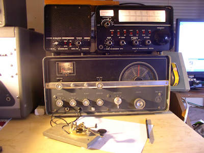
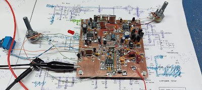
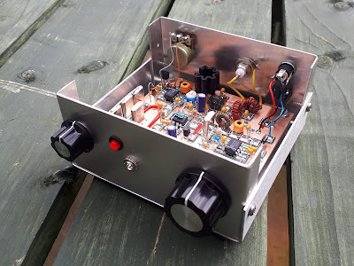
I have in front of me two transceivers: The Mythbuster uses a 9 MHz Clapp circuit (see below). The 17-12 rig uses a Colpitts Circuit. I checked the tuning linearity of both. Both appeared quite linear in tuning, with no real difference between the two.

Then I looked at the tuning capacitor in the Mythbuster 17-12 rig. It came out of an old Hallicrafters transmitter, probably the HT-44. I looked closely at the stator and the rotor plates. Both are curved. I’m guessing that this may yield a more constant change in capacitance for a given movement of the main tuning dial.

Next I opened up the VFO on the Mythbuster. (It is the VFO from an old Yaesu FT-101.) I couldn’t see the stators very well but it appears that their shape is different from the square shape we often see in variable capacitors. Could it be that this variable capacitor was also made to provide linear tuning?

Back in 2013 Norm Johnson wrote about all this in the Antique Radios.com forum:

A capacitor that has uniform increase in capacitance with rotation will have the stations at the high end of the band squeezed together. Another type known as the straight-line frequency variable capacitor has, as you might guess, a characteristic that gives even spacing of frequencies with shaft rotation. These were popular in the 1920’s but weren’t very good for superhets where you needed to have a dual section capacitor that would tune both the RF and local oscillator, and have them track each other properly. The midline variable capacitor is more compatible with a superhet, and easier to make both sections track properly. This is the type that you see in most receivers from the late 1930’s to the end of the tube era. They don’t have quite the equal spacing between stations across the band that the old straight-line frequency caps had, but they’re much better than the variables that change capacitance linearly with rotation.

I wrote an online calculator that helps in the design of the tuning. It shows what frequency range you’ll get with a specific type of variable capacitor, including the effects of padder and trimmer capacitors. It also displays a dial scale that shows how the frequencies are lined up accross the dial.
http://electronbunker.ca/eb/BandspreadCalc.html

Steve W6SSP also provided some really good info back in 2013:

There are three types of open, variable plate caps;
SLC= straight line capacitance where the capacitance varies linearly,
these are the most common and have half-circle plates
SLF= straight line frequency where the plates are tapered to allow
for linear tuning of the frequency
SLW= straight line wavelength, you get the idea…

SLF and SLW caps have oblong plates.

The effect on tuning a receiver can be dramatic. One example is the
Hammarlund SP series of receivers where the ham bands are very
compressed at one end of the tuning range. They used SLC caps
in the VFO. On the other hand rigs like the Kenwood TS-520
and FT-101 series have linear tuning across each band. These use
SLF variable caps. Most old 1920’s battery radios used SLW
where stations were identified by their wavelength.
Steve W6SSP

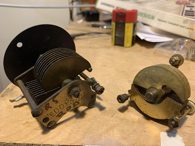
These two variable caps came out of my junkbox. Both are Eddystones, made in England. My guess is that the one on the left is SLF. But could the one on the right (out of an old regen) be SLW?


The Drake 2-B also has perfectly linear tuning. I looked at the manual: “The tuning condenser is of special design…” I’m guessing that they used an SLF variable capacitor. The 2-B had no need for ganged capacitors — the “preselector” was tuned via a separate front panel control.

I looked at the tuning dials on my Hammarlund HQ-100 receiver. It is fairly linear in its tuning, but not as linear as the HT-37 or the Drake 2-B; on all of the tuning ranges the frequencies seem to spread out a bit at the lower end. My guess is that Hammarlund used the midline variable described above by Norm Johnson. The HQ-100 did use a ganged variable cap, with one section tuning the RF amplifier and the other tuning the local oscillator.

Mythbuster on the bottom. 17-12 rig on the top

SolderSmoke FDIM Interviews: Hans Summers G0UPL Talks about the QDX and His New Balloon Tracker

Thanks to Bob Crane W8SX for getting us this wonderful interview with Hans G0UPL. Its really amazing to hear Hans talk about how many QDX rigs and Baloon Trackers have been sold by QRP Labs, and how quickly they sell. Really great. Hans’s comments on the realities of the parts shortage was also very interesting.

Listen here (about 7 minutes): http://soldersmoke.com/2022 G0UPL.mp3

U4B Balloon Tracker

Marconi the Fascist

For obvious reasons Marconi stories pop up in my news feeds. This morning an article from Wales reminded me of a very dark and disheartening aspect of Marconi’s life: his fascism and his participation in the persecution of Jews.

There have been at least 14 stories in SolderSmoke extolling the technological virtues of Marconi. I even met his daughter Elettra while in Rome and wrote it up for the blog. But it is just wrong to sing Marconi’s praises while ignoring his fascist involvement.

His fascism wasn’t even separated from his radio work. He won fascist honors and he won his appointment to Mussolini’s Academy of Italy because of his radio work. Take a look at this quote:


He became President of Mussolini’s Academy of Italy — and it was in that position that he participated in the persecution of Jews. He was a member of the Fascist Grand Council.

If you have doubts about this, just take a look at the short clip (above) from Marconi’s 1937 funeral procession. Note the fascist salutes, note Mussolini himself marching in the procession.


The article from Wales:

Tim Hunkin on Prototyping, Welding, and on Being a “Jack of all Trades”

I always like Tim Hunkin’s videos, even when they are not directly related to radio electronics. In this one we learn about his prototyping techniques — this does seem similar to what many of us do when building rigs.

I liked his explanation of welding, and of the dangers of the angle grinder (his precautions on this device were similar to those in a recent video by “Spirited Man” Van Neistat).

Tim’s final comment on how in the modern world we seem to have moved away from the notion of having one person skilled in many different areas — we are now very specialized, so the “Jack of All Trades” is increasingly rare. That’s a shame. Oh well, we can be Jacks of all Trades in our radio shacks.

Thanks Tim!

TV Homebrew 84 years ago — Tracking Down W9YEI’s 1939 Television Receiver — The CRT He Probably Used — Please Help Find More Info

A recent Hack-A-Day article about early television receivers got me thinking about the receiver built by young Johnny Anderson in 1939 and described by Jean Shepherd on WOR in 1973. In the 1973 program (skip to the 18 minute mark), Shep gives a good description of the device. It sounded a lot like the receiver from Peter Scozzari’s October 1939 “Radio and Television” article: Shep described a big chassis with angled pieces of aluminum one of which had a tube socket brazed onto it. Anderson may have bult the power supply on the same chassis as the receiver. Shep said that a 1 inch CRT was in this socket. Tellingly, he described the picture as being green in color.

Peter Scozzari wrote that oscilloscope tubes produced a “greenish hue.” One month after his first article, in November 1939 Peter Scozzari published another article in which he changed the CRT to to a tube that would produce a black and white (not green) pictures. See below for the part of the article that describes the shift to the larger black and white tube. This supports the idea that Anderson was using a tube built for oscilloscopes. The picture above shows what images from the three sizes of RCA oscilloscope tubes would have looked like (absent the green hue — this was a black and white magazine). I find them kind of eerie, considering that the person in the picture was probably born more than 100 years ago. And in that bottom picture we see an image (absent the green hue) very similar to what Shep saw in 1939, and described so vividly in 1973.

Scozzari’s receiver started out with a 2 inch tube, then a month later, he went with a 3 inch tube. But Johnny Anderson may have only had the 1 inch tube described by Shep. The Sherman QST article provided circuit details for all three sizes of RCA tubes. This information would have been very useful to Johnny Anderson. So my guess is that when Shep saw TV for the first time in 1939 in Johnny Anderson’s basement workshop, he was looking into an RCA 1 inch 913 CRT.

Here’s a great EDN article on the 1 inch CRTs available in the 1930s:

Here’s a fellow who recently built a TV receiver using an RCA 902:
Here’s the YouTube video of his 902-based receiver in action:
Previous SolderSmoke blog posts on this topic:

This is all pretty amazing: We are gathering details on a television receiver built some 84 years ago by a teenager in a basement in Hammond, Indiana.

Does anyone out there have more information on what Anderson built? Can anyone dig up more information on this? Any more info on Peter Scozzari? Anyone have info on Jack Neitz of California (he recently built the Scozzari TV receiver)?

Colin M1BUU’s Homebrew Manhattan SST

Wow, especially on St. Patrick’s day I think it is appropriate to say ” ’tis a thing of beauty. “

Colin did a great job on his homebrew version of the SST transceiver. It looks like his is on 30 meters. I especially liked his description of the troubleshooting that followed the construction. the assist provided by AA7EE’s blog was especially cool, and demonstrates the long-lasting power of internet-shared tribal knowledge.

Colin wrote (on Facebook):

I was inspired by Bill and his adventure with the SST-20, so I started gathering a few parts last year to build a Manhattan SST. I did a joint SOTA activation with a fellow homebrewer ham at the end of January and we started talking about classic portable CW rigs, it turned out that we both had an SST build on our ‘list’. I was challenged to build the SST for the next joint SOTA activation!
It took a lot of effort and a few late nights but I did manage to produce a rig capable of making QSOs for a joint SOTA activation of Fair Snape Fell, G/SP-007. I’d done a solo activation of Pendle Hill G/SP-005 a few days before with the rig for a trial run and I discovered that the AF was very low. After some troubleshooting I noticed that I’d soldered the LM386 gain set capacitor to an incorrect pad. Doh! I fixed my error and the rig had much more gain.
I found that with the improved AF gain, the rig would squeal if the gain was turned up. I was ready to give up really, but after a cool off period, I began researching the issue and it turns out that it’s very common and indeed I found posts from 1997 about it! It seems as though my recreation was so faithful to the original, I’d included the original flaws too! I added in a 0.1uF cap and resistor connected to pin 5 of the AF amp chip as per the suggestion on Dave AA7EE’s blog and now the squealing has stopped.
I’d made 14 QSOs during the joint SOTA activation, so I considered my challenge to have been met! It’s been a bit of an epic build!
73, Colin, M1BUU

Bluetooth, Winston Churchill, The Speed of Light, and a 1938 Zenith Receiver

Hello Bill –


It has taken me a while to put hands on keyboard to send you this message, but having seen or heard a few more of your references to Jean Shepherd, I felt I must. Being a fan of vintage radio equipment and the American scene of the late 1930s, sometime back I acquired a very nice circa 1938 Zenith 5-S-119 AM/Shortwave radio.


Though it had been recently re-capped, it took some effort to get the thing working (needed a new power transformer), and still needs to be aligned, but it made a nice addition to my 1930s NYC Art Deco-inspired office. One reason I bought it was to add a Bluetooth receiver to it so I could listen to podcasts, etc, from my phone. I like the big electromagnetic speaker that those radios have and thought it would be cool to bring this one back to life. I picked up a small Bluetooth receiver board and a power supply for a few dollars online and got it working in the Zenith with no difficulty, except for some AC hum and oscillator noise that I will work on when I have time. So, success!

But here is the Jean Shepherd part. I recall one of his broadcasts in which he offered his theory that every radio transmission ever made is still out there, traveling further and further into intergalactic space and getting weaker and weaker, but still there. What an idea that was. I would say he is right. I have pondered the idea ever since. So being also a Winston Churchill fan, what would be the first recording I would play through the Bluetooth? What else but his 1940 blood, toil, tears, and sweat speech! So there was the scene — the Churchill speech playing the same audio waveform through a radio that might very well have played it live (or close to live) back in 1940! Almost (though not quite) like detecting the original still-traveling radio signal out there past the star Phi2 Ceti or wherever it is now!

Well that was a quick adventure this past summer that I thought you might appreciate.

Keep the Solder Smoke podcasts coming!

Tom Fuhrman, WX2J