
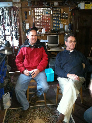
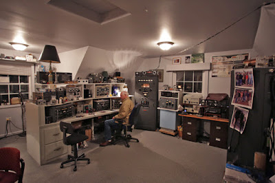
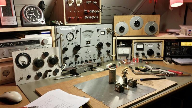
Very cool video. We have visited VE7ZWZ’s amazing shack before. This time he takes us inside a BIG commercial AM transmitter that he has modified for use on the amateur bands.
I know that he had the plate voltage turned off, but I still felt myself cringing when he reached up to touch the plate connectors on those enormous thermatrons. The filaments were on, adding to my unease. Dude, don’t do that! And if you are standing INSIDE the transmitter, keeping one hand behind your back might not be as beneficial as it normally would be.
His comments on his VFO were interesting. I was kind of disappointed that he went with a varactor circuit. A varactor? Amidst all those bread slicer variable caps? It just doesn’t seem right. (And BTW they are bread slicers, NOT “potato slicers.”) But I kind of liked the heater–thermistor–insulation set up that keeps the VFO at constant temperature.
I thought it was interesting that these transmitters were kept on, with the tubes glowing for years at a time.
Thanks Mr. Carlson, for another great video!
Category: Tubes
Video of a REAL Homebrew QRP Contact (by WU2D)
I think Mike’s video does a good job of showing what it is really like to get on the air with simple, homebrew QRP gear. It takes some patience and operating skill. I guess it is sort of like fly fishing (with home made lures); there are easier ways to catch fish, but they are not as rewarding.
Wonderful “QSO Today” Interview with Ian Keyser G3ROO
N2CQR and G3ROO
I knew it was going to be a good Sunday morning in the shack when I saw that Eric 4Z1UG had posted an interview with Ian Keyser G3ROO. This wonderful interview brought back memories of my visit to G3ROO’s amazing facility in Dover. (Thanks to Tony Fishpool who brought me out there.)
In this interview, you will hear Ian state — in a very nonchalant English way — that he built his first receiver at age 8. And I really loved the story of how Ian got his call sign. FB Ian.
Ian is a very prominent member of the G-QRP club. I was oddly relieved to learn that he is working on a LEGAL LIMIT LINEAR AMPLIFIER. I hope he has special dispensation from Rev. George Dobbs. I intend to cite this project if we ever have to defend Pete Juliano from charges of QROism.
Listen to the interview here:
That is a key designed for use aboard a hydrogen balloon. This is the kind of thing that Ian has in his shack.
This is Ian’s variometer — mentioned in the interview.
That’s me using one of Ian’s spy sets.
Ian’s antenna book:
Here are the SolderSmoke Daily News posts about Ian and the Dover Construction Club:
Boatanchors! HT-37 to HT-37 contact with W1ZB
Jerry W1ZB and I met up on 40 a week or so ago. He was running a Hallicrafters HT-37. This spurred me to clear up the T/R problem that had knocked me out of the competition on Straight Key Night (I’m sure I would have won!). One spray of DeOxit D5 on the HT37 relay contacts was all it took. Jerry and I set up a schedule for this morning on 40 minutes. Above you can see a short video of the first part of our HT-37 to HT-37 contact.
Jerry has an amazing collection of beautiful old tube radios. Check out his QRZ.com page:
https://www.qrz.com/lookup/w1zb
BTW: Speaking of old rigs talking to identical old rigs: Last night on 40 I worked TI2NF in San Jose, Costa Rica. He was running a Collins KWM-2 to a Collins 30-L1. It was real nice to talk to somebody who was using an unusual rig. Right after we finished, VE3OCZ called TI2NF. VE3OCZ was ALSO running a KWM-2 to a 30-L1. TRGHS.
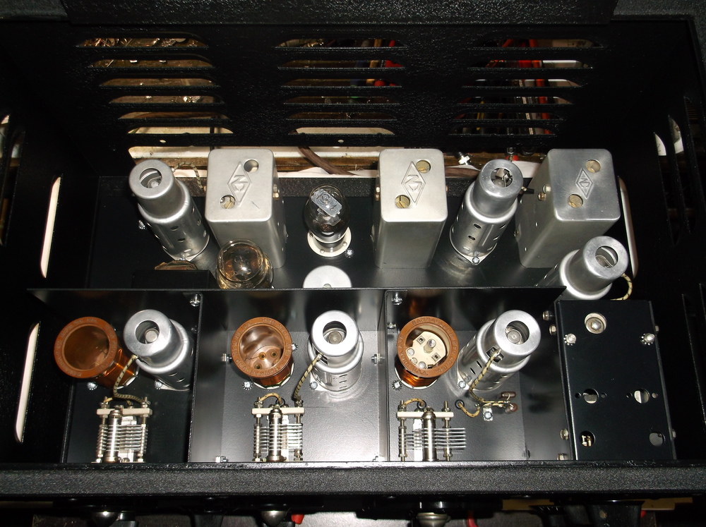
NO3M’s Amazing Homebrew 1934 Single Signal Superhet
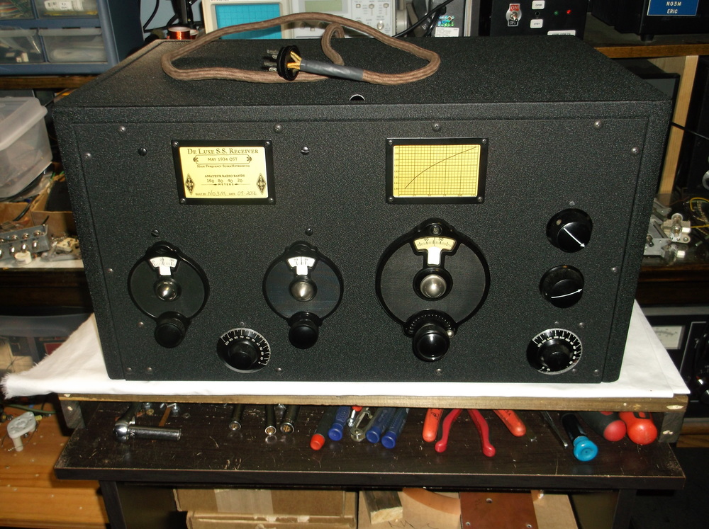
Jim AB3CV reminded me this morning about the work of Eric NO3M. Jim was pointing out that breadboard construction need not be ugly and that Eric’s work is the proof of that. Indeed.
Almost one year ago, I worked Eric on 160 meters. He was using one of his beautiful breadboard rigs:
Jim’s reminder sent me once again to Eric’s site. I see he has been melting a lot of solder, and to very good effect. In just three weeks he built the magnificent 1934 QST “Single Signal Superhet” pictured here.
Eric has a great series of articles on this project, with excellent pictures and videos:
Bravo Eric!
HB2HB: Butch K0BS with a KWM2 and a Hombrew 4-1000 Amp
Wow! Now THAT is a shack! This morning I heard Butch K0BS and his friends on 40 meter SSB. I knew I was listening to the voices of kindred spirits when I heard them talk about a drifting VFO and the need to heat up the filaments of an ART-13. As the group was shutting down to begin their preparations for Thanksgiving dinners, I gave Bruce a call with my BITX 40 Module. He was on a KWM-2 (the rig that had been drifting a bit) and a homebrew 4-1000 amplifier. I told him that I think a bit of VFO drift is a sign of good character.
You really need to check out the pictures on Bruce’s QRZ.com page:
https://www.qrz.com/db/K0BS
Happy Thanksgiving to all who are celebrating the holiday.
DONE! Jan’s AMAZING Mate for the Mighty Midget Receiver

Hi Bill,
Finally the Mate for the Mighty Midget is finished, just in time for the G-QRP Valve Day 12-13th of November.
Got the LO fixed for 40m by lowering the parallel capacitor from 150 pF to 100 pF.
Also the 68 pF series capacitor was lowered to 33 pF for some more band spread on 40m.
It now receives from about 7.0 to 7.4 MHz and from 3.45 to 4.0 MHz
Had to exchange C1 in the end, the one used initially quit every now and then.
I only had a large 3 section variable in the junk box covering 10-550 pF, which works fine now.
For the lower end of 80m I had to add additional 47 pF next to the 47 pF trimmer caps, so there it is about 600-650 pF max!
For the lower end of 80m I had to add additional 47 pF next to the 47 pF trimmer caps, so there it is about 600-650 pF max!
At the high end of 40, it is also just not too much.
The meter was used as a position indicator for C1.
Tried several ideas, but with no separate tube for AGC, I couldn’t get it to work as a S- meter
Read something about audio derived AGC, maybe this is worth a try.
The BFO can be switched off for AM reception.
Simultaneously the input on the mixer side of the crystals is disconnected but still coupled by some capacitance of the switch wires.
AM reception is possible, but not very good.
Need to find a better solution which doesn’t degrade the crystal filter properties to much.
(By the way, the detector regen. control ads about 4 dB to the AM sensitivity)
The receiver will mainly be used for CW/SSB reception, so maybe it stays this way for a while J
I hooked it up to the W1TS transmitter, which was very loud.
Didn’t foresee a T/R relay (learned a lot from this project 😉 ), so added this one between the front plates next to the RF and audio gain control.
The quit down everything a little, the RF gain pot is lifted of ground as suggested by James, N2EY at QRZ.com.
It helped a lot, but was still too loud if tuned exactly in the bandpass of the crystals.
The T/R relay now also switches an adjustable potentiometer at the input of the audio pre-amplifier.
The dial cord has no lag, and works very well for fine tuning.
Unfortunately the reduction drive went from 1:19 to 1:9…, the tuning capacitor only has a 180 deg. span.
Something to remember for the next receiver.
It’s a nice little receiver and quite stable after warm-up.
The only extra luxury a next receiver will have, is AGC.
But with no AGC it’s easier to tune the antenna tuner by ear J
There’s now a complete homebrew station here, antenna, feeder, tuner, receiver, transmitter, power supply, al home made J
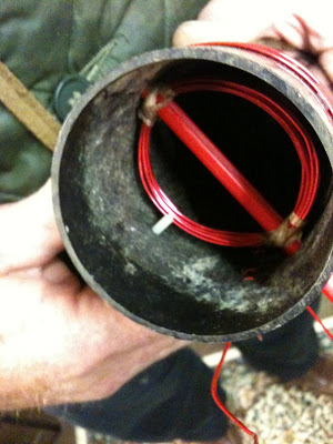
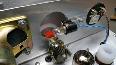
About the Mystery Hole….
If you haven’t guessed it by now, or Pete hasn’t told you, it is revealed in one of the pictures below.
I also made a little video:


K1RID’s 6L6 CW Transmitter from QST: “Barracks Bag VFO”
A new old thermatron device is coming to life on the kitchen table of K1RID. Don’t spill the coffee on that thing Ed.
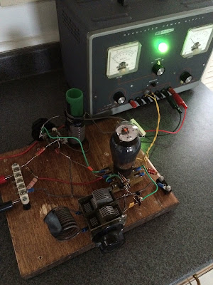
First Signals from the PA3GSV Mighty Midget Mate
Obviously the Radio Gods (Spirits in the Sky) approve of Jan’s work. How could they not? I can now see why he took the trouble to cut that hole in the sewer pipe cap that forms the large wheel on his homebrew reduction drive. But what are we going to see through that center hole Jan? What will the frequency readout be like?
———————-
Hi Bill,
Just finished the last stage of the Mighty Midget MK2.
There are first signals!
The first one I heard was a broadcast station, believe it or not, the song that was on was “Spirit in the Sky” ..
All stages were built, tested and as far as possible, adjusted separately.
It was built from back to front, so the RF amplifier was last.
I added an ECL82 for more audio, the first thought of only using an EL84 didn’t bring enough.
The triode of the ECL82 as a pre-amp, the pentode as final.
Furthermore ECF82’s were used instead of the 6U8, they’re more widely available over here.
The Miller coils are hard to come by, so the 300 uH coils are homebrew.
Also used a grid detector instead of the two germanium diodes.
The triode of V1 originally intended for audio was used for this.
Made the BFO adjustable as well, still remember the screwdriver sticking out of the coil on your side…
Happily there was not much troubleshooting needed.
The 80m coil was only 5 kHz off, the 40m coil 300 kHz (to low in frequency), still have to fix that.
Initially the receiver worked reasonably well without adjusting, but C1 quit at some point.
After some investigation, the problem was a dirty wiper contact on the rotor.
An ultrasonic bath fixed the problem, so no looking out for a replacement there. (hope it stays that way)
After adjusting, sensitivity is around -114dBm (0,4 uV) / 10 dB S/N! (with the FT241 crystals in place, and careful tuning of the controls)
Really not bad for this small receiver, Lew McCoy was right, it really is a Mighty Midget.
I wanted to make some video’s, but over here there’s a terrible S9 rattle from 160 to 15 meters.
Every now and then it appears out of nowhere, and disappears the same way.
As soon as it is gone, I’ll make some video’s.
I made one video though, just after completing the receiver.
Reception on CW and SSB sounds really well, but unfortunately didn’t record that.
The receiver is not finished yet.
Next to the 40m coil, S-meter has to be tried, and there’s still some work on the cabinet and front panel.
More to follow.
73 Jan
PA3GSV
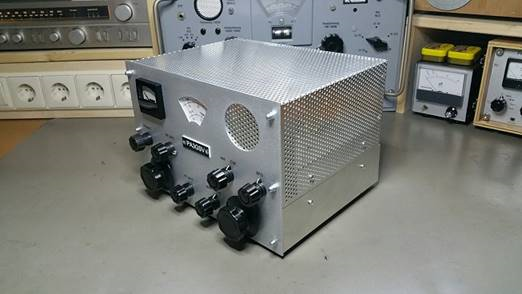
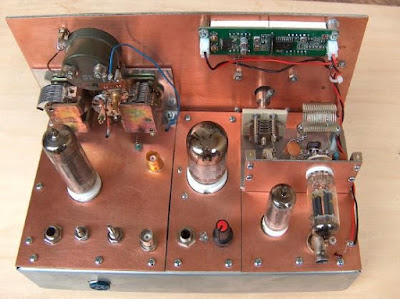
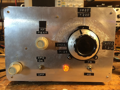
Jan PA3GSV’s Amazing Mate for the Mighty Midget
We have featured the amazing homebrew work of PA3GSV before:
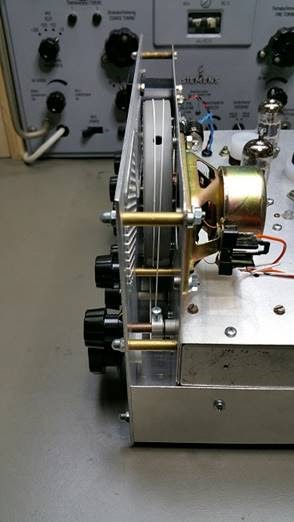
Jan is at it again, this time building a Dutch version of Lew McCoy’s Mate for the Mighty Midget. Look at front panel! But wait, there is more!
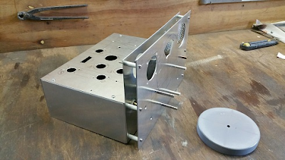
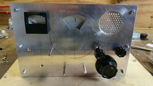
Here is a side view of the chassis. Wow. What, you may ask, is that round thing?
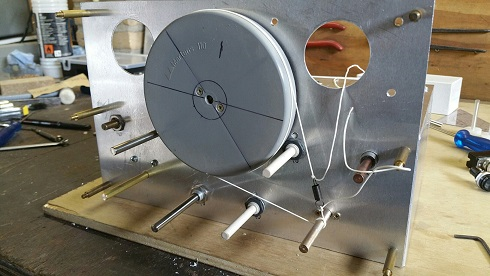
Holy cow! Homebrew Vernier reduction drive made from the cap of a sewer pipe. And a homebrew dial cord arrangement. Jan is clearly breaking new ground in ham radio homebrew re-purposing.
Jan writes:
Bill:
Here a little update on the MMrx.
Got almost all the parts, except for the Miller 4411 300 uH coils, for which I am attempting to make my own.
While I was looking for some pictures of this coil, if it was shielded or not (found a vintage online Miller catalogue J ),
I stumbled across this article, the W2MQ “Hamster”
There is no mention of the MMrx, but the text is very in line with the latter. Nice read.
Also while looking for parts, I saw this supplier of FT-241 xtals who sell for reasonable prices ($10) .
Maybe you already know this company:
Vernier drive 1:19
The drum is made from a sewerage end cap got from the hardware store.
Still under construction J
Added a front control to switch the BFO on/off, together with another crystal or some arrangement to make AM (broadcast) reception possible.
I want to try a regen detector instead of the 2 germanium diodes, followed by a pentode for some more audio output.
Regen and AF gain control are also at the front.
In your video it looked like there was a screwdriver sticking out of the BFO oscillator coil, a trigger to put this control on the front as well J
As there is no AGC, the (S) meter will measure the plate current of the RF amplifier tube.
So, a lot of experimenting to do, and still busy with some of the mechanics.
73 Jan
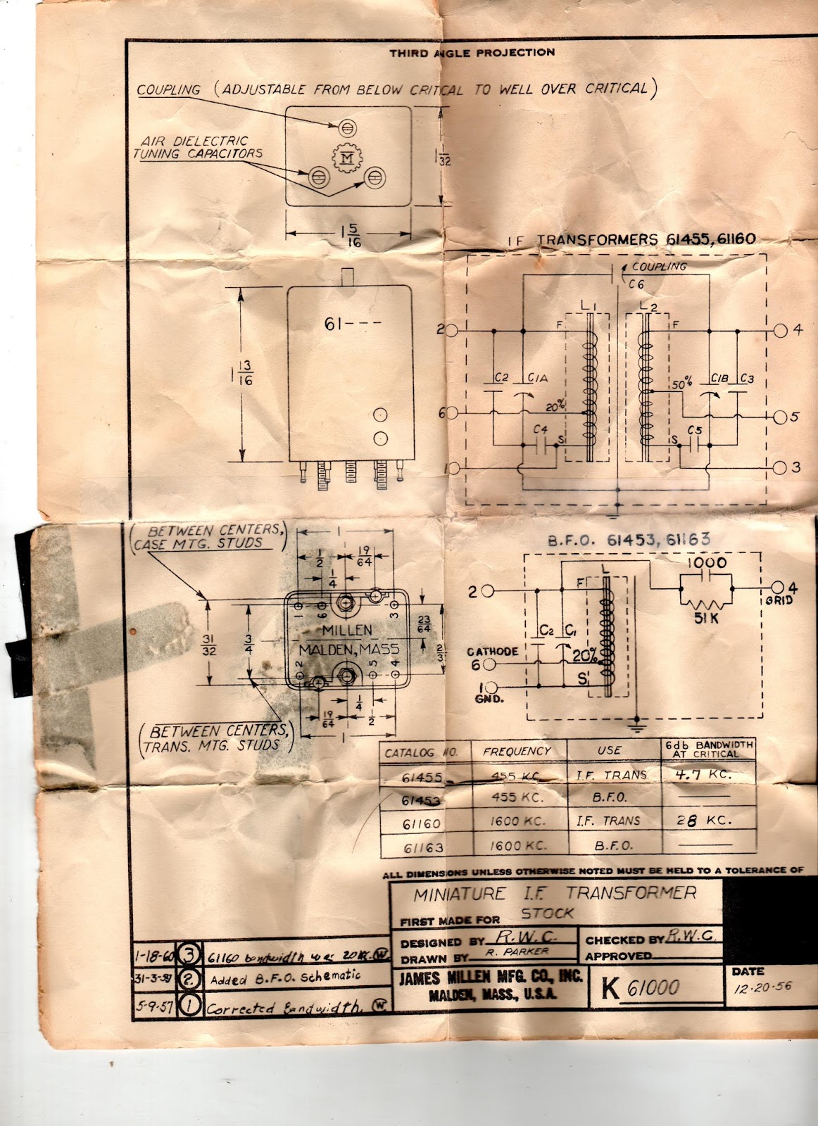
Inside a Millen 61455 IF Transformer
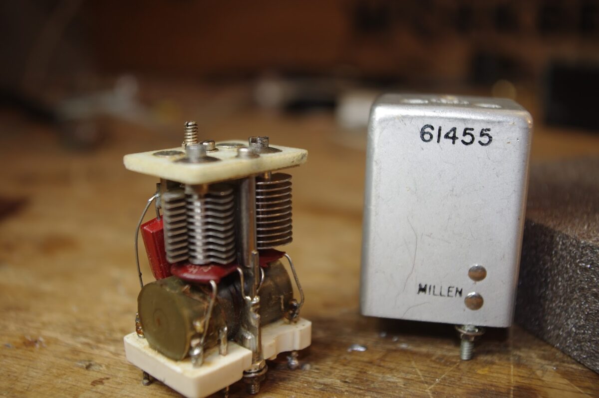
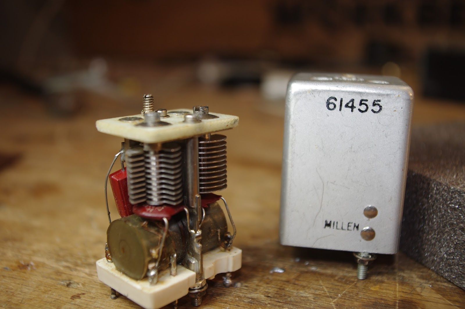
I found this in my junk box. I’ve put it in my old Mate for the Mighty Midget receiver, in the place of the Toyo CM455 crystal-mechanical filter (which I found to have excessive insertion loss). I think its very cool how they squeezed two variable caps into that little can. Designed in 1956. Works great. Note the promised passband: 4.7 kc at 6 db down. Not bad for an LC device.
Here is the spec sheet:
Excitatation! The Inspiring Knack Story of N3IC
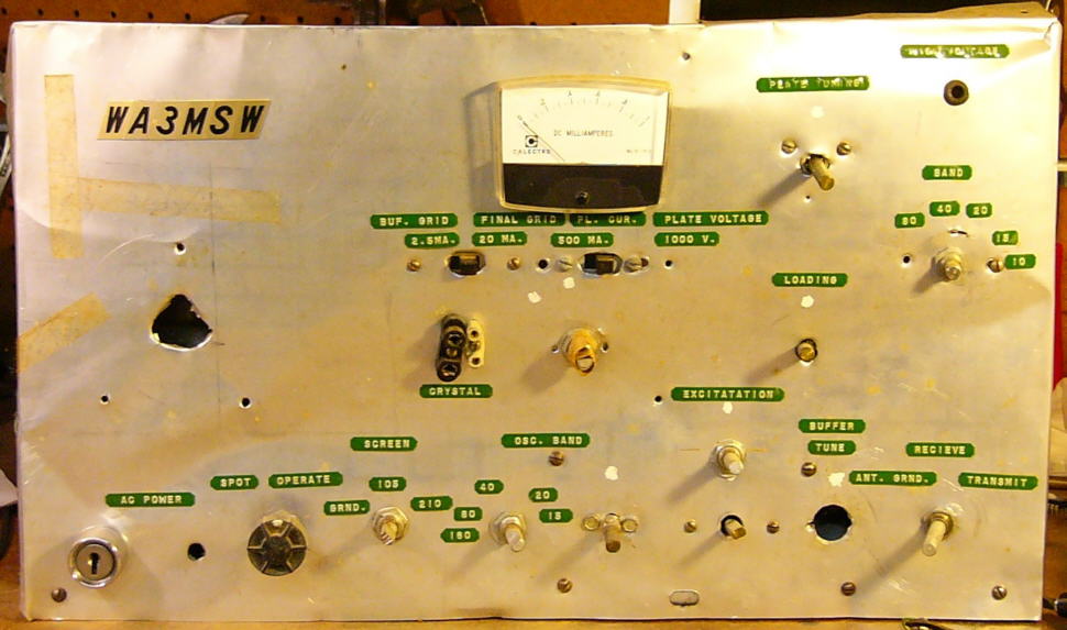
Steve Silverman sent me this link. This web site has been getting a lot of attention from the solder melting community. And justifiably so. Behold (above) the first transmitter built by Robert Glaser, now N3IC, circa May 1969. The chassis and front panel were made from flimsy printing press sheet metal. Note the key (as in lock and key) switch that the OM put on the front panel — he took his responsibilities under FCC regs quite seriously. My favorite part of this rig’s story is that when he got it done, he didn’t have the two 6146s for the final. So he just took a capacitor and used it to connect the driver tube to the output network. Brilliant! With that arrangement he made his first contact. No wonder he labeled it “Excitatation!” It was clearly more exciting than your standard excitation.
Those TV power transformers look very familiar. I was using similar devices to build a power supply for an HW-32A a few years after Dr. Glaser built this rig. It’s a wonder we survived.
FB. Check out his site. It is a wonderful catalog of all the stuff this very prolific builder has made over the years:
Ham project here:
A broader range of projects here:
Manhattan-style Vacuum Tubes: “An Evolution of Thermatron Homebrew Techniques” by Grayson Evans

Grayson Evans was at Dayton. Scheduling problems prevented him from being interviewed by ace correspondent Bob Crane, but Grayson was kind enough to e-mail us the essence of his presentation. And it is really wonderful. He brings the advantages of the Manhattan construction technique (fast prototyping, all components on the same side of the board, easy modification) to the world of tubes (aka valves or, as Grayson prefers, thermatrons). We also see in Grayson’s work an admirable willingness to bridge the digital-analog design, to bring into his rigs the best of the old and the new. Thanks Grayson!
Grayson writes:
An Evolution of Thermatron Homebrew Techniques
For a long time I have been trying to develop some techniques to prototype Thermatron projects as easily as the typical “Manhattan style” solid-state construction. Thermatron projects you see now-a-days still use the traditional technique of mangling aluminum-drilling and mounting everything to a “bud” style chassis. This just takes too much time and my projects always look disappointing.
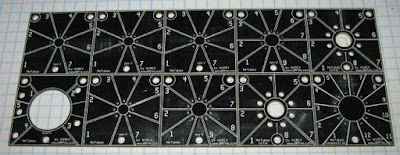
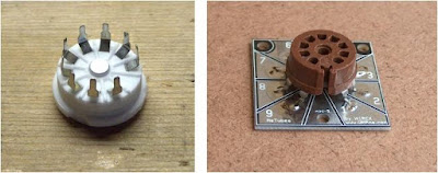
Fortunately, around two years ago, Rex Harper, W1REX, came to the rescue after hearing an earlier talk of mine and developed a set of thermatron socket pads. The MeTubes panel from QRPme consists of 10 prototype pads for thermatron sockets. The panel has v-scores for breaking the panel into single tube pads. The panel has pads for mini 7 & 9s, octal, compactrons and acorns. Awesome.
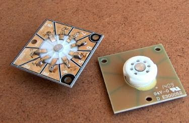

The best sockets to use with the pads are PCB style. These provide a large pin area to bend out and solder to the pad (see photos).
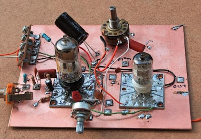

I pre-mount a dozen or so of the 7-pin and 9-pin sockets on MeTube pads so I have them ready to go when prototyping. The “crude” example below shows and 7 and 9-pin socket on one of my prototypes. I think this was a microphone amp for my AM transmitter. Pardon the mess.

The nice thing about the pads is that they provide plenty of room to tac solder lots of parts to a single pin–easy to add or remove parts. This is a lot easier than using the traditional tube socket pin.
Prototyping thermatrons in this way is FAST. No more punching out holes to hold thermatron sockets in aluminum chassis!
But it is still nice to be able to have the thermatron on the “top” of the board and the components on the “bottom” of the board. To do this and still use the MeTube pads, the thermatron has to be mounted on the other side. I did this by mounting the socket through the MeTube pad. This requires making a hole in the center of the pad to pass the socket through and then soldering the pins in the usual way. This is way easier with PC mount thermatron sockets and make a very nice installation.

This technique has some great advantages over using the traditional socket with pins. The pad has a lot more room to mount components to each pin. Normal thermatron socket pins are difficult to attach more than two wires and it’s a bit more difficult to get a good solder connection. The pads are easy to solder to and allow components to be easily attached in any direction since the “socket” is now flat.
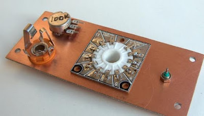

It is also easy to attach the socket/pad to a copper clad board. The same hole must be made in the copper clad board to pass the top of the socket through, then the pad is superglued to the board in the regular way.
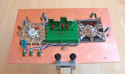
This is another example of “right side up” thermatron mounting on a prototype test board for crystal filters. I mounted a small “plug board” (not sure what you call these things) in the center to allow me to easily swap filter components. Notice the acorn thermatron soldered direct to the pad. The board works great, the filter design sucked. I gave up. Maybe too much distributed C.

I used this technique, combined with Roger Fell’s idea of using inverted aluminum chassis, to build my latest project, a QRP AM/CW transmitter. I’ve been wanting to try out a few new ideas and this seemed like a good project to try them on. I also wanted to build the transmitter in modular “blocks”, interconnected in a similar way to Rogers. It worked pretty good although I am still trying to get the thing to work right. Even new construction techniques can’t cure my screwups. BTW, the ANALOG VFO is ROCK SOLID. +/- 10 Hz over 30 min. Even I was impressed. The Hartley oscillator is the best circuit for thermatron circuits by far.

A 12AU7 Atop a Raspberry Pi
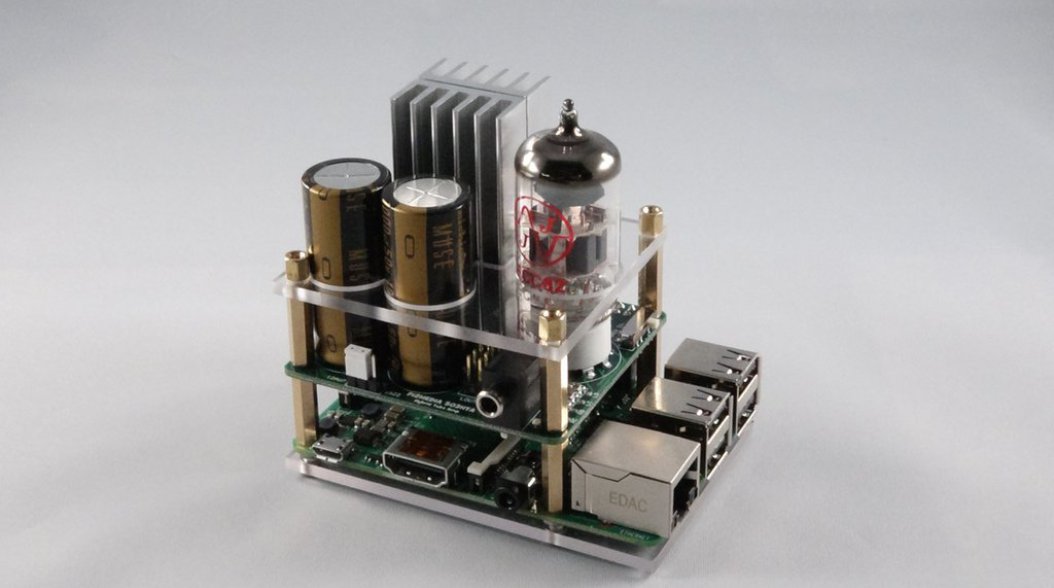
http://makezine.com/2016/05/06/warm-tube-tone-is-just-what-the-raspberry-pi-has-always-been-missing/
I don’t know what to say. One moment I find myself thinking that this could represent “the best of both worlds.” A minute later I’m thinking that this thing is a horrible chimera. And it has a whiff of audio fool-ism about it, don’t you think? Will it work better with oxygen-free cables and gold-plated fuses?
Still, overall — pretty cool.
1625 Tubes and Si5351 Chips: JH8SST’s FB Rig
Peter has been helping Jun JH8SST and other Japanese hams get their Si5351 synthesizers working with various displays. Jun has had some great success as you can see in the above video. I really like the combination of old (1625) and new (Si5351) technology.
Jun is a long-time homebrewer who as built some amazing stuff. Check out the pictures on his QRZ.com page:
And look at his cool 128×128 TFT display:
Other videos here:
A Reduction Drive for the Mighty Midget’s Mate Receiver
This morning I put a reduction drive onto the main tuning cap of my 6U8 Mate for the Mighty Midget receiver. Before I had been directly turning the 35 pf variable cap. The tuning rate was a bit too high for easy tuning of SSB stations. This drive went in nicely and it does reduce the tuning rate considerably, but it feels a bit tight. Is there anyway to loosen up one of these drives?
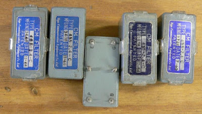
The meaning of “CM” in the Toyo CM-455 Filter
 |
| Photo by ZS1KE |
A while back I picked up (from e-bay?) a 455 kc crystal filter for use in my Lew McCoy “Mate for the Mighty Midget” receiver. I did a quick and dirty installation. It kind of worked, but I had it in the back of my mind that I had to work on the impedance matching to ensure minimum passband ripple. But when I learned what the P, B, E, and G pinout designations meant (plate, B+, earth and grid), I realized that this device had been designed with tube impedances in mind, so I probably didn’t have to mess around with input and output networks (as I’ve done with the BITX rigs). Last week I installed it as the manufacturer intended — it sounds great.
Today I started wondering about the passband characteristics of the device. What do the skirts look like? So I started Googling. There is not much out there, but I did come across a really interesting Epson site that describes the origins of this filter, and what the CM means. CM is for “Crystal Mechanical.” Wow, this little box combines the characteristics of a crystal filter AND a Collins Mechanical filter:
An excerpt:
“While at the Electrical Communication Laboratory of NTTPC, Mr. Nakazawa had had a flash of inspiration: ‘We could develop a crystal unit with a high Q factor by using the wire mount technology I’m studying now. Then, if we can achieve the idea of a mechanical filter that mechanically joins multiple units using quartz material, we should be able to develop a compact filter that achieves both excellent filter characteristics and thermal characteristics.’ Without a pause, he quickly tackled the next development issue, which resulted in the creation of the ‘crystal mechanical filter (‘CM filter’)*5). This CM filter was manufactured by processing the quartz substrate into an ‘H’-shaped filter element and functioned by using the long thin sections on the left and right sides as resonators (Figure 1). The middle portion connecting the two sides fulfilled the role of the coupler. This was precisely the ‘mechanical filter achieved using crystal (quartz)’ that Mr. Nakazawa had envisioned.
This filter was released on the market as a 455kHz intermediate frequency (IF) filter for single-sideband (SSB) modulation in radio communications. The use of quartz material meant that not only were good filter characteristics achieved, but thermal characteristics were also excellent. As this was the first filter to offer properties of this caliber, it sold extremely well throughout the world. Furthermore, this technology received the honor of being granted the Notable Invention Award from the Science and Technology Agency.”
Does anyone have the specs on these filters, and perhaps a passband graph?
Three cheers for Mr. Nakazawa!
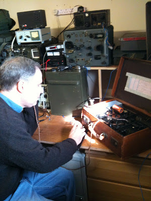
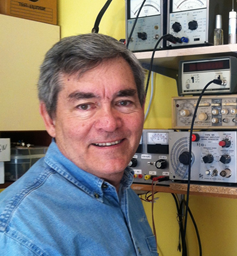
My Mate for the Mighty Midget Thermatron Receiver
A few days ago I received an e-mail from Jan PA3GSV — Jan is working on a receiver similar to my old Mate for the Might Midget and had some questions about how I’d handled the filter portion of the circuit. Then on Sunday, while listening to Eric’s interview with Farhan on the QSO Today podcast, I got so enthused that I felt compelled to work on a homebrew receiver. So out came the old Mate for the Mighty Midget. I built this thing in 1997-1998. It is described here:
In the above video I was listening on 75 meters to a very congenial early morning roundtable featuring W4CH, K5KBZ and others. I know, I know, this is the third or fourth video that I’ve made of this thing. This is almost as bad as 2B-mania. Or the Michigan Mighty Mite thing. I blame Jan. And Eric. And Farhan. And Grayson. And Lew McCoy!
Here is my e-mail exchange with Jan:
Bill:
I recently build the W1TS two tube xtal controlled transmitter, and am looking for a 80/40m companion for this that has a crystal filter.
At first, I wanted to build the “Simplex Super” and finally got hold of the 1700 kc crystals, but then they got lost in the mail…
Only part of a two box shipment arrived, with 455 kc fundamental frequency FT-241 crystals, so now I am looking for a diagram using a 455 kc IF. Jan
Jan: In this link you will find the schematic for the receiver I built.
I was not able to build the filter with the two 455 kc crystals. I could not obtain the needed crystals. I used two 455 kc IF transformers as described in my article. This resulted in a very broad frequency response but it was OK and quite good for AM.
Last year I put in a Toyo 455 kc SSB filter, but I did not match the impedances, so the results were not good. Your e-mail makes me want to work on this again!
Let me know how your receiver turns out.
73 Bill N2CQR
Thanks for your reply.
It is a neat looking little receiver.
And yes, I also have a cardboard box labeled “good junk” which is filled with stuff from ham fests J
Finally it will be put to good use!
I printed the article for some evening reading this week.
It will take me some time building this receiver, as there is some metalwork and mechanics involved.
I will let you know how the receiver turns out, and I am also curious what improvements you make on yours.
Thanks again, and I will let you know.
73 Jan PA3GSV
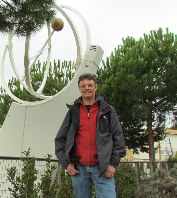
Wow, Jan has the Knack! Check out his station:
That’s the W1TS rig on the left. More pictures from Jan on his QRZ.com site. He too uses wood cabinets! I’m not alone! Here’s Jan, PA3GSV
Grayson Evans TA2ZGE on “QSO Today”
Eric 4Z1UG has a really great interview with Grayson Evans TA2ZGE. I’m writing this as I listen.
My reactions:
I sympathized completely with his reaction to EE professors who insisted that current flows from positive to negative. Indeed. Let’s turn those arrows in the diode and transistor symbols around!
I too stripped down a Heathkit VFO and rebuilt it from scratch.
I share Grayson’s aversion to metal work. Viva Manhattan!
Here is the interview:
Could Grayson’s Arduino Thermatron Shield Protect Us From Digi Domination?
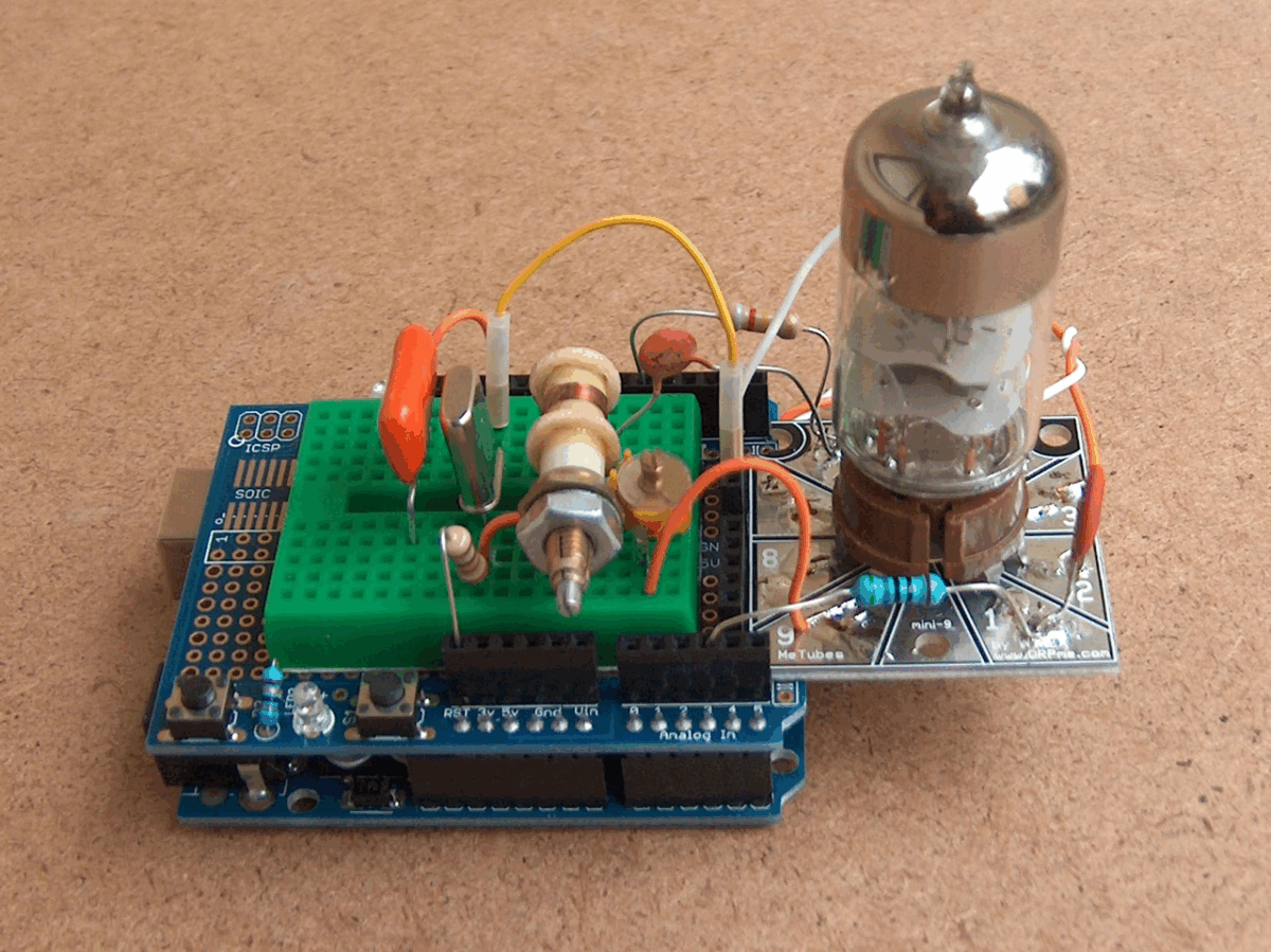
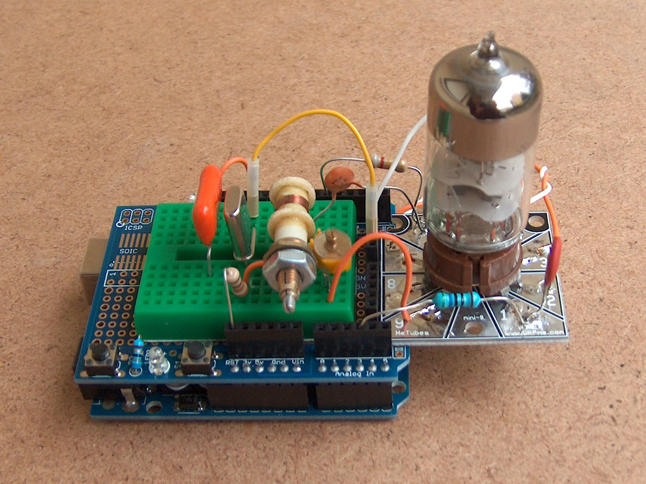
Something old, something new, eh Grayson? The author of “Hollow State Design” is engaged in an (I suppose) admirable effort to bridge the gap between our beloved Thermatrons and those new-fangled Arduinos. Here Grayson tries to explain and justify his flirtation with the dark side:
I want to do some experimenting with Thermatrons and Arduino. Sound weird? Maybe not.
I really like playing around with the Arduino even though it violates my ban on digital technology in my shop. (My excuse is I am trying to use it teach my son something he can use to get a job someday.)
Sure Grayson. That’s what they all say. “I was doing it for the kid…”
Kidding aside, that tube shield looks pretty cool. And I like the MeTubes base for the Thermatron.