“Our customers are interested in technology – some people buy paintings for their wall; our customers buy a technical piece of art. I think they appreciate the fact that someone is keeping old technology alive and they want to support us.”
There is a lot of Tribal Knowledge in this video. And good discussion of the many moral issues faced by those of us who work on old gear. — Mike seems apologetic about his blatant and blasphemous spray painting of the Drake copper chassis. As well he should be. — His stubborn replacement of the tube socket (to allow for shielding) seems wildly reckless to me. The Radio Gods may retaliate with some unexpected instability in that circuit. — He CORRECTLY refers to the rewiring of the final circuity (to accomodate 6146s) as “the evil thing.” Indeed. — I love in the beginning how he is listening to some ham radio chatter and the guy is talking about the selection of COM PORTS. With old radios “we don’t have COM PORTS — we have an antenna connector.” Well put Mike. — I was struck by how much the TR-3 innards look like my 2-B receiver. But the TR-3 has no dial strings. That is a major technological improvement. And it has a PTO. Was this a case of Collins envy? — Mike adds a useful word to the lexicon: “shotgunning” — the indiscriminate replacement of entire categories of parts in old radios. Now I don’t mind shotgunning the electrolytics (some people bitterly oppose this). But I agree with Mike on the wisdom of keeping the paper caps in there. I am looking forward to Part II. These videos are like “This Old House” but instead “This Old Rig.” And I will go back and look at Mike’s video on the Power Supply refurb. Thanks Mike.
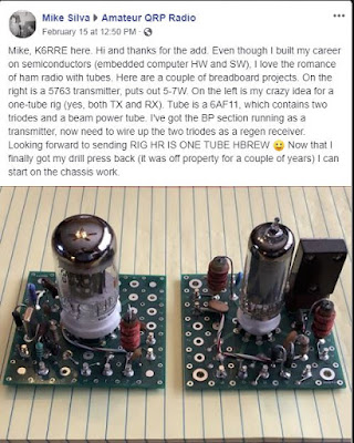
I was really impressed with Chuck KE5HPY’s 12AU7 Quarantine Regen! A very nice build and my hat is off to him! It caught my eye, as I also built a 12AU7 regen during this period, my first “Hollow-State” unit in sometime.
It would be interesting to find out what other construction projects fellow hams have involved themselves with during this trying time.
Thanks for upping the frequency of your podcasts. Each one is a welcome note to break-up the COVID monotony.
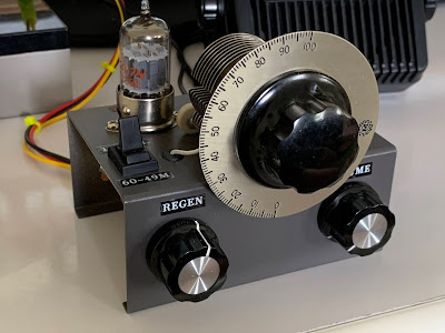
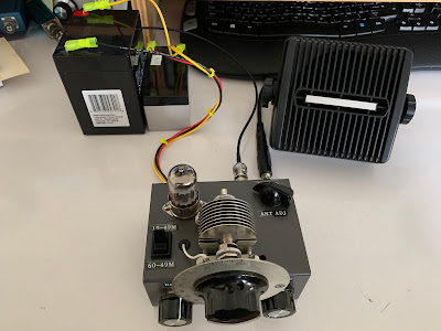
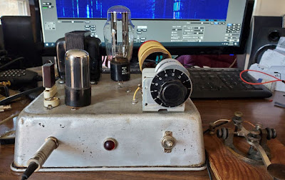
Following on to Bill’s 31m rx, I am pleased to have a new regen on the air and performing well. This started as the 12AU7 Hartley circuit found on the web; however, the original circuit needed some further work IMO. I made a number of modifications – outboard 30 MHz LPF (to remove our local Spanish FM station), inductive antenna link, variable cap for antenna coupling adjustment, up to 24V on the plate, extra by-passing, NE5532 audio section vs LM386 and a switched cap for a lower “band”. It’s still a starved triode oscillator/audio amp and it has that regen presence. Best DX is Singapore (BBC) and Madagascar although it’s ideal for easy listening on 19-60m to Romania, Greece, Cuban music, Spain, etc. As Bill said, there is still plenty worth listening to on a homebrew AM rx. 40, 30 and 20m copy OK, but bandspread is tricky! Adjusting regen is good for +/- 1 kHz, kind of a poor man’s BFO adjustment. I heard a TI station calling CQ on 20m and called him back on my Icom for a QSO.
By the way, this rx has some serious vintage mojo – Hammarlund varicap, National coil form, Millen dial and an RCA tube. The all-star team plays great together! It’s a kick seeing the filament glow while putting RF through recycled parts made decades ago.
Greetings from a fellow ham in Northern Virginia. I have enjoyed the SolderSmoke podcast for a few years now, and I just heard your recent presentation to the Vienna Wireless Society. We have a lot in common so it is about time I reach out to make your acquaintance.
I was born in NYC and grew up in Northern NJ. I was first licensed in 1969 as a high school student (51 years ago! Goodness!). My novice callsign was WN2JFX, and I progressed from Novice and then to General and Advanced as WB2JFX, and then eventually to Extra (in about 1990 — while the 20 WPM code requirement still existed). At that point I put in for a 2X1 callsign and received WX2J, which is a nice twist on my original call.
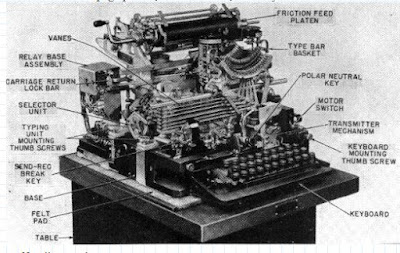
I was fanatically active in my early years in ham radio. My Elmer (George, K2VVI, SK) set me up with a DX-40, and my parents provided a brand new Hallicrafters S-120 (you could copy the whole 40 meter band without changing the frequency!). I think I Worked all States as a Novice and learned that the human brain is the most amazing audio filter on the market. When I made General, George lent me an old Hallicrafters SX-25, and then I was really in good shape. Besides CW, I was also very interested in RTTY. I had my own Model 15 leaking oil in the basement and had a blast watching the magic of that thing printing messages out of thin air. I have always been a home-brewer, and one of the first serious things I built was a two- or three-tube RTTY demodulator from the Handbook. Aluminum chassis, chassis punches, tube sockets — the whole works. I have no idea what the real inductance was of the inductors that went into the filters but somehow if the signals were strong enough, and on 850 Hz shift, it could actually demodulate signals. I probably still have that thing around here somewhere.
Another local ham bequeathed me his entire collection of 73 magazines – 10+ years starting with the first issue (~1960). I read them from cover to cover so many times I probably have them memorized. I became a real fan of Wayne Green, W2NSD, who was always ornery and controversial but a very interesting guy. I met him at a hamfest many years later and we had a great chat.
In any case I wanted to mention some other things that resonate with me as I listen to your podcast. As a kid growing up in the shadow of NYC in those years, you can bet that the Jean Shepherd broadcast was a regular part of our life. My dad used to listen to it every night — 10:15 p.m. I believe, on WOR — and we both used to greatly enjoy his stories of lighting up the fuse panel and nearly blowing up the house as he and his old man were playing with radios, etc. It was a common theme in our house too when my ham radio signal would blast into the TV set or I dangled new antenna wires off the house and out of the trees — “You’re going to blow this house up!” I studied electrical engineering in college and was commissioned in the Air Force upon graduation. I served a 20-year career in the Air Force and stayed somewhat active in ham radio. I was licensed and operated out of Okinawa (KA6TF) and England (G5ERE) during tours of duty in the early 1980s. Always an HF guy, in about 1982, in Japan, I bought myself a new Icom IC-720A, and this is still my primary rig. I was an early adopter of PK-232 and did some extensive building and experimenting with it. Sadly though, in the last 25+ years, my ham radio experience has mostly been vicarious as my work and family obligations have just not left much time for ham radio. I do have a G5RV wire antenna strung up but very rarely jump on the air — sometimes during contests.
In high school we made a field trip to ARRL HQ in Newington, CT. While there we did all the things people do on such a visit, but one of the high points for me was meeting Doug DeMaw. I can just hear how Shepherd would describe it — “I turned the corner and there he was! In person! The high priest of homebrewing! Doug DeMaw. In the flesh!” Cue the kazoo. I actually also met Shepherd at a book signing (Wanda Hickey’s Night of Golden Memories?). I remember presenting him with a computer-printed banner of his callsign — K2ORS — produced by one of the few functioning computer programs I had written in high school. I also heard him on the HF bands one night — I think he was in Florida — and actually made contact with him, if barely being able to exchange callsigns can count as a contact.
Well, more than you wanted to know. I just wanted to let you know that I enjoy your podcast and can personally relate to very much of what you say. Although I am steeped in Hardware Defined Radio, I am also a software guy so I expect that my future includes SDR. I hope you and Pete are able to continue the podcast for a long time to come because I need the full HDR-SDR spectrum to be covered — hi.
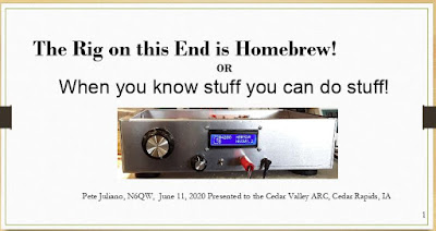
Earlier this month Pete N6QW spoke via Zoom to the Cedar Valley, Iowa Amateur Radio Club. This was an especially appropriate venue for Pete, the creator of the KWM-4; Cedar Rapids was the long-time home of Collins Radio. Many of those in the club used to work for Collins.
For the Zoom connection, Peter used his Linux Mint computer.
Pete mentioned that Gene Senti, while tinkering in his basement, developed the KWM-1. One of the guys in the audience confirmed Pete’s account, but added something: Collins employees could buy ham gear at a discount. Senti bought a brand new 75A4 receiver (commercial price in late 50s was about $900) and he modified it from being just a receiver into a transceiver. Imagine taking a new radio and doing that! But when he got it working, Art Collins came over to his home to see the invention. The rest is history.
Pete got grilled a bit on why he was still using “analog’ front ends on his several SDR builds — why not Direct Digital Conversion? Pete says he may now try to build a DDC rig.
There was also a lot of very nice feedback on the SS Podcasts – there were many regular listener’s in that group. You can see Pete’s slides here: http://soldersmoke.com/N6QWslides.pptx
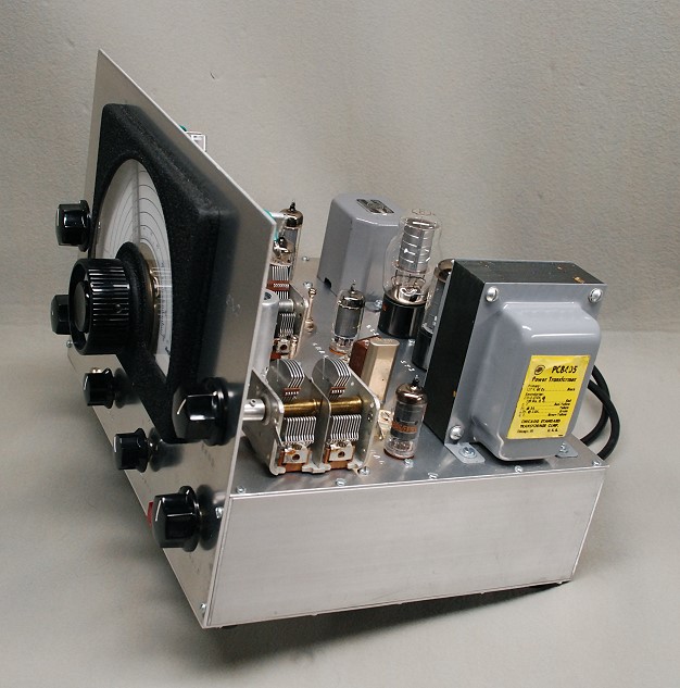
Alan Wolke W2AEW and I were recently discussing our Drake 2-Bs (again!). Both of our receivers have reduction drives between the main tuning control and the string mechanism that moves the main tuning capacitor. I wondered if these were the results of modifications by previous 2-B owners. I vaguely recall that my Elmer — Hilmar WB2NEC — had done this sort of mod.
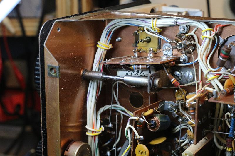
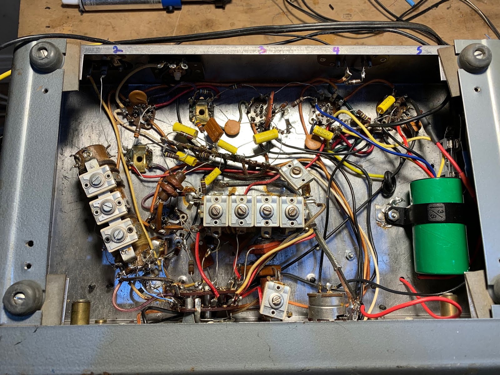
OM Wouter ZS1KE sent me this very illuminating photo of the inside of his Drake 2-B. No reduction drive. So Alan and I obviously have modified 2-Bs.
One thing that puzzles me: I can’t seem to find a single article that describes this apparently common mod. Does anyone know of an article in the ham magazines that might have described how to do this?
The 5-part PBS series from 1985, “Radio Collector” was nominated for a Los Angeles Area Emmy for Best Informational Series. Radio Collector was shot in 1985 on 3/4″ video, a marginal format that boasted 240 lines of resolution. It was edited 3/4″ to 3/4″ using a control track/insert cuts-only editor, then that 2nd generation 3/4″ was transferred to 2″ at KOCE in Southern California where the credits were added. KOCE sent it to PBS and it was available to all member stations, and it has been aired on many stations. Mike Adams’ students in Radio-TV-Film at California State University, Fullerton, were the camera operators, musicians, etc. Twenty eight years later CHRS President Steve Kushman transferred a copy of a copy of a copy of the master which went from 2nd generation 3/4″ to 2″ to 1″ to Beta SP to his computer. The story has held up well, and of course many of those profiled here are silent keys/valves. Mike’s inspiration for this series was the original “This Old House,” thus “This Old Radio.” Enjoy
Every dark cloud has a silver lining. Here is a very small silver lining for this terrible COVID-19 situation: I had time to do a proper replacement of the electrolytic capacitors in my Drake 2-B. Three cheers for Hayseed Hamfest LLC for providing the replacement capacitor. Go to their website to find capacitors for many other old rigs: http://hayseedhamfest.com
— Copper Clad board: Pete’s boards use CEM 1. CEM 1 is low-cost, flame-retardant, cellulose-paper-based laminate with only one layer of woven glass fabric.
— Peter VK2EMU continues to build his amplifier. But it is NOT for 50 MHz. It does have 6 different meters on the front panel. But it is not a 6 meter rig!
— Rich K7SZ – “now look what you’ve done”Fixing up an S-38
— Rich WD3CProvided some great SWL links:
https://www.short-wave.info/ if you move the green dot to your location it will predict what the signal strength would be at your location and will also allow you to search by station, language, frequency, etc.
My work on the S-38Es, on the HRO-dial receiver, on the Mate for the Mighty Midget, and on various mechanical filters has caused me to think (once again) about why we ended up with 455 kHz as the IF frequency for so many radios. I’ve heard many explanations for this, but unfortunately I’ve forgotten the explanations and lost the sources. I started digging into this again today. I found the below e-mail from Al N3FRQ on the Boatanchors mailing list (2008). I contacted Al to find out if he had learned anything else on this topic. He has not. So if anyone out there has answers to Al’s questions, or anyother info that would shed light on why they went with 455, please let us know. ——————————-
Every so often the question comes up: Why are all the IF’s 455 KHz? I’d like to get an article together that solves this riddle while the people who know are still with us. I know parts of the story, but I need help with a couple of issues. There are two major consideration is the choice of the intermediate frequency used in a superheterodyne receiver. The lower the frequency, the easier it is to attain high selectivity. Also, in the early days, before tetrode and pentode tubes, it was easier to achieve a high degree of amplification at lower frequencies. Conversely, a higher IF frequency results in better image rejection. Early superhets had the IF at 100KHz or lower in order to get adequate gain from the available triode tubes. They suffer severely from “two-spot tuning” (images). By the early 1930’s, broadcast set had settled in at 175KHz, and automobile receivers would later adopt 262KHz as a standard. The advent of the short-wave craze, and multi-band broadcast receivers dictated a higher IF frequency to achieve adequate image suppression on the short-wave bands. The broadcast band occupied 550-1500KHz at this time, and the designer encounters sever problems if his radio tunes across it’s own IF. Some shortwave sets used 1600-1700KHz for better image rejection, but one couldn’t go higher if the 160-meter ham band (1800-2000KHZ) was to be covered. Most multi-band receiver settled in near 450KHz, a comfortable distance from the first broadcast channel at 550KHz. Questions: Odd multiples of 5KHz, 455, 465, etc., were usually chosen so that the image of the carrier of a broadcast-band station could be zero-beat with the carrier of the station being tuned to achieve minimal interference. (This assumes 10KHz channel spacing. Did the Europeans (9KHz) do something else?) The Radiotron Designers Handbook, Third Edition, p. 159, states “A frequency of 455 Kc/s is receiving universal acceptance as a standard frequency, and efforts are being made to maintain this frequency free from radio interference.” (1) Do FCC and international frequency allocations reflect this? (2) I’ve heard the term “Clear-Channel IF.” Can anyone cite references? (3) At lease one news group posting claims that broadcast frequencies in a particular market are assigned to prevent strong inter-modulation products from falling near 455KHz. Is this factual? Need reference.” (4) Was this (3) at least part of the reason for “Radio Moving Day” in 1941? See: http://www.dcmemories.com/RadioMovingDay/032341WINXFreqChange.jpg (5) Many National Radio sets used a 456KHz IF’s and I think I remember a 437 somewhere. Why? Are there different considerations for short-wave CW operation? Further input, corrections, and elaborations are greatly appreciated. Scolarly reference will be looked upon with great favor. Regards, Al -- Al Klase - N3FRQ Flemington, NJ http://www.skywaves.ar88.net/
It is always a pleasure to see a new video on Mr. Carlson’s awesome YouTube channel, especially in these days of Staying-In-The-Shack (SITS). Obviously Mr. Carlson is doing his bit in this area. FLATTEN THE CURVE! Thanks OM! My recent bout of S-38E madness has peaked my interest in the All American Five design, so this March 10, 2020 video was especially interesting to me. Mr. Carlson puts out so much great tribal knowledge. I didn’t know about “rounder” resistors. I didn’t know that you have to be careful not to short out (to the IF can case!) the 455 kc transformers. I really like his approach to dial cord restoration. Mr. Carlson’s discussion of the adjustment of the front end tuner circuit on this broadcast band radio was very interesting. Unlike the S-38 radios, there are no front end coils being switched in as you change bands. In fact, it appears that that big coil/antenna inside the back cardboard piece IS the front end coil. This discussion has caused me to question my front end alignment technique for the S-38E. Did I have an appropriate antenna or antenna substitute across the antenna terminal when I set the peak on the input LC circuit? I will check on this. Hooray! One more thing to do during the COVID-19 SITS period. UPDATE: I checked on this using the test set up described in an earlier post, but this time with my antennas connected. First with a 40 meter dipole, then with my 130 foot doublet, then with a 50 ohm dummy load I was still able to see the resonance dips at exactly where I wanted them to be. My favorite bit of Carlsonian wisdom from this video? Mr. C’s confirmation that some hum in All American Five receivers IS NORMAL! (This may be too much for the folks who find normal band noise to be offensive.)
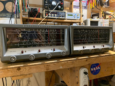
I have been talking bad about the Hallicrafters S-38E receiver for several years now. For a long time I agreed with my friend Pete Juliano in his colorful description of the receiver: “a pig with lipstick.”
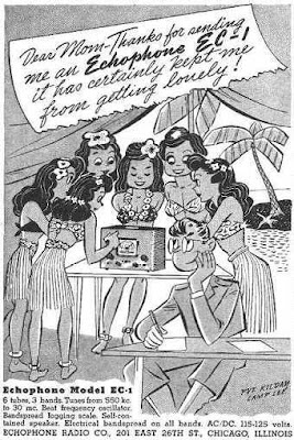
But as I’ve gotten to know the receiver better, I have come to like it. It is very simple. There is a certain minimalist thing that explains the attraction; it is a challenge to make the most of this very low-budget 1950’s receiver. It uses tubes, but the voltage is not really in the very lethal range. It covers a wide range of frequencies. Its frequency stability is fairly good. And it sounds great on AM (scroll to the bottom to listen). It seems to be technologically related to the Echophone EC-1 — we have been posting about the WWII advertisements featuring Hogarth and his (unbelievable) efforts to attract women with this receiver.
The S-38E has a big “picture window” frequency dial, marked with exotic foreign locations (Java!). I share with it a similar vintage with the S-38E: IGY. The S-38E was produced from 1957-1961. Duck and cover my friends; the CONELRAD frequencies are marked on the dial. Working on these two receivers has kept me busy during the first few days of the COVID-19 emergency.
I now own two of these things. I might get a third. I thought it would be worthwhile to write up my experiences with the S-38E. I hope this information will be of use to others who might work on this piece of gear.
Winterfest RX on the left, junker on the right
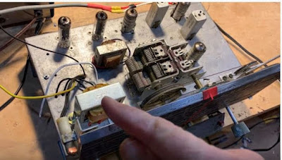
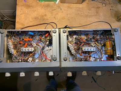
SHOCKINGLY BAD? I had an S-38E as a kid. Around 1980, I gave it to my cousin Mary’s husband Mike so he could listen to shortwave broadcasts. Recently I asked him about that S-38E — he said it had given him a nasty shock. That was because of the “transformer-less” AC/DC power supply — if you plugged the AC line cord in “the wrong way” you would be putting 115 V AC on the chassis. Ouch. AC/DC DESTROYS AN ANTENNA COIL I picked up an S-38E at a Vienna Wireless Winterfest a few years ago. I think I paid ten bucks. I didn’t pay attention to the polarity of the AC plug and managed to plug it in the wrong way. Then I managed to short the antenna terminal to what turned out to be a very AC hot (115V) chassis. This destroyed a significant portion of the antenna coil. Smoke was released. ISOLATION TRANSFORMER Not wanting to repeat the hot chassis disaster, I installed an isolation transformer. On the junker, I used the Triad N-49X, available from Digikey. In retrospect I probably should have gone with the larger, 35 watt N-51X, but Fred KC5RT provided a great suggestion that would make the smaller N-49X adequate: Run the filaments in series DIRECTLY from the AC line, with neither side of the AC line to the chassis. Then run the rest of the circuitry through the isolation transformer. This would take a lot of current out of that little transformer and would likely make replacement with a larger unit unnecessary. I will try this later. Update: 2 April 2020: I tried to run the S-38E with the filaments in series fed with AC directly from the line cord and the rest of the circuit running through the isolation transformer. I got it working this way. Sort of. But AC hum was a lot louder and I found myself back in the AC/DC transformerless situation with the chassis going hot if the set is plugged in “the wrong way.” So I retreated, going back to having the whole receiver running off the isolation transformer. The hum went back to the earlier (normal) level and the chassis would not go hot no matter how I plugged it in. On the Winterfest S-38E it looks like I had used a larger isolation transformer. I put a 500 ma fuse in the primary circuit. On the N-48X the black lines are primary, the red are secondary. One black line goes to the fuse, then on to the front panel on/off switch. The other side of the switch goes to the AC line. The other side of the AC line goes to the other black line. Neither of the AC lines goes to chassis. On the secondary side, one of the red lines goes to Pin 4 of V5 (rectifier); the other goes to the B- line which is Pin 3 of V3 the 12AV6 which is also connected to the volume control. I put the isolation transformer on the top side of the chassis. It ends up close to the speaker, and fairly close to the AF output transformer. This raises hum concerns.
Where I placed the isolation transformer on both my S-38Es
HUM? I did a test to see if my placement of the isolation transformer was adding to the hum. I simply took the S-38E back to its original transformer-less configuration and then listened to the hum. I noticed no difference and concluded that the isolation transformer is NOT adding to the hum. If there is a difference, I’d say that there is less hum with the isolation transformer. (And yes, I did make sure the AC line plug was in the correct way with the old power supply configuration.) See what you think:
The hum is not really a problem. You can only hear it when the volume control is turned all the way down. As soon as you turn the volume control to the right, band noise overwhelms the hum and you can’t hear it any more. I think this was the normal condition of this very economical receiver. The two receivers have different speakers. The Winterfest speaker measures 7.6 ohms (DC) and the junker has a 3 ohm speaker (closer to that called for in the schematic). I think the 3 ohm speaker results in somewhat less hum. REPAIRING/REPLACING THE ANTENNA COIL
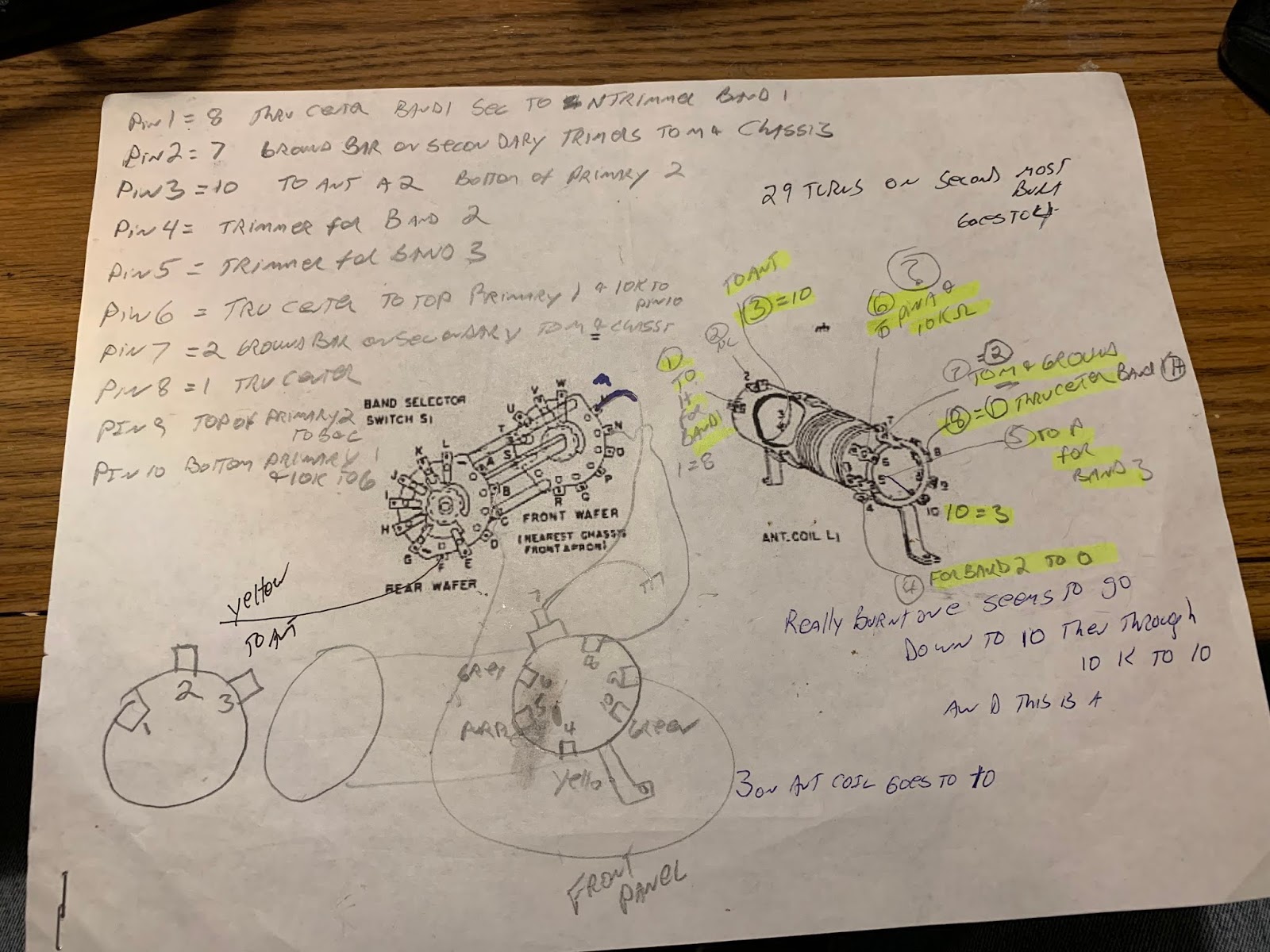
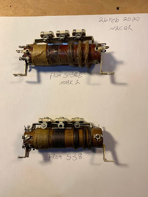
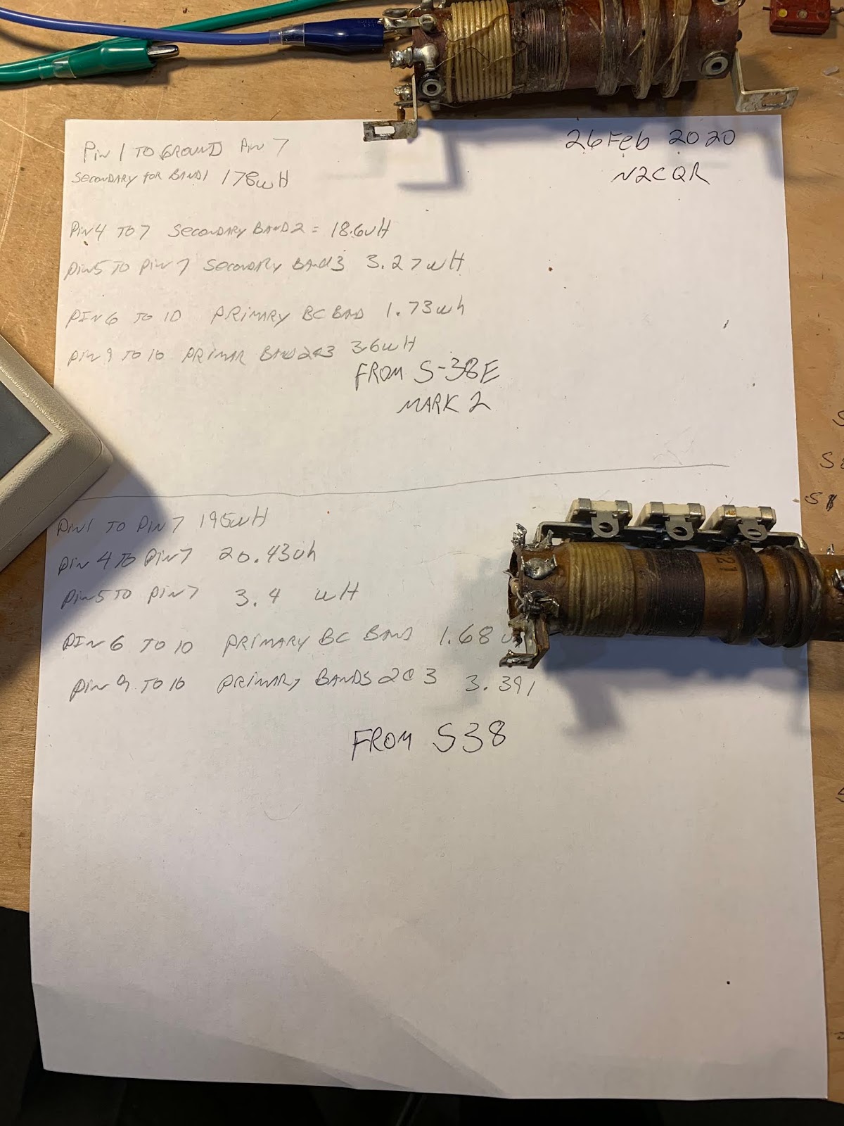
After the smoke release, I tried to re-wind the burned out portions of the antenna coil on the Winterfest S-38E, but I got tired of the project, cursed all S-38s, and sent mine to the basement/crawl space. I would have given it away, but I was afraid that the recipient would electrocute himself. So it sat in the basement for a couple of years. Recently I got interested in shortwave listening again, so I pulled out the S-38E. On e-bay, I found and bought an S-38 antenna coil. I put it in my S-38E, hoping that it would bring the receiver back to life. But I had a lot of trouble with the front end alignment. I theorized that the coil I had bought was from the original model of the S-38, and perhaps the S-38E coil had different inductances. So I went back to e-bay. There I found a junker S-38E being sold by Mark W1MEM. It had been owned by KA1WFY. At the suggestion of Scott W1NB on the AntiqueRadio forum, before installing the coil from the junker, I measured the inductances of the S-38E coil and the previously obtained S38 coil. I was surprised to find that the values were almost identical. That meant that my theory about coil inductance differences was incorrect. But I took the S-38E coil from the junker and put it in my S-38E. I took note of the fact that the junker did not in fact look like junk, but there it was, sitting on the floor of the workshop, having had its antenna coil extracted. And I had in hand the old S-38 coil that I knew from testing was very close in value to the S-38E coil.
I was kind of getting tired of S-38s at this point, and I thought about leaving work on the junker S-38 for another day (or another year, or decade), but familiarity with the innards of the rig and alignment procedures is perishable, so I decided to try to get the junker going while it as all still fresh in my mind. I installed the isolation transformer mod on the junker and put the S-38 antenna coil in. That is how I came to own a second S-38E.
RF ALIGNMENT PROBLEMS One of the problems I had was that the alignment instructions for the S-38E are very sparse. For the front end alignment, they just tell you to put signal generator signal into the antenna terminal, put a meter or scope on the audio output then tweak the antenna and oscillator coils for max output. I had no trouble getting the oscillator on the right frequency — for bands 2 and 3 that would be the signal frequency PLUS .455 MHz. For Band 4 it would be signal frequency minus .455 MHz. But I could not get the LC circuit in the front end to peak on the input frequency. Now, if you have the peak for the input LC circuit in the wrong place, your receiver will still work (sort of) but image rejection will be even more horrible than it is designed to be. For example, assume you want to tune a strong signal at 7.0 MHz. Your VFO is at 7.455 MHz. The difference frequency is .455 MHz. This signal goes through the IF transformers and you hear the signal. But now tune down .910 MHz to 6.09 MHz. Your VFO will be at 6.545 MHz. 7.0 – 6.455 = .455 Unless the front end LC filter blocks the strong signal at 7.0 MHz, it will also show up at 6.09 MHz on your dial. If the S-38E is aligned properly, that front end LC circuit will track the tuned frequency. In this case it will be peaked at 6.09 MHz and the strong signal from 7.0 MHz will not get through. Oh happy day! That 7.0 MHz signal shows up only on one place on the dial. All is right with the universe. Of course there is another image problem. If you are tuned to 3.9 MHz, your VFO is at 4.355 MHz. If a shortwave broadcaster fires up on 4.81 MHz, well 4.81 – 4.355 = .455 That is why I can hear “Brother Stair” raging away, seemingly at 3.9 MHz. Even if a simple receiver like this is properly aligned, a powerful shortwave broadcast signal will often get past the puny single LC circuit in the front end.
But what happens if the S-38E is misaligned? What happens if that LC circuit is peaking above the desired frequency? Now when you tune to 6.09 MHz, the front end tuned circuit may be peaked at say 6.5 MHz. There is only one tuned circuit in this receiver front end, so the “skirts” are quite wide. Wide enough to let that 7.0 MHz signal through to the mixer where it mixes with the 6.545 MHz VFO output to produce a very audible output. This is what was happening when my S-38E was misaligned. The 40 meter ham band and the 75 meter hambands were both showing up at two places on the dial. After alignment, this problem disappeared.
I realized later what my problem was: I was putting far too much faith in the accuracy of the frequency readout needle on the front panel of the S-38E. Many of these receivers had had their dials restrung over the years, so in many cases the placement of the needle was significantly off. MY RF ALIGNMENT METHOD
What you really need to do is this: At first, don’t pay much attention to where the red or yellow frequency indicators are pointing. View them as rough measures. Put a signal generator across on the A1 antenna terminal, with ground from the sig gen going to both A2 and GND. Then put a scope probe across the same A1 -A2/GND terminals. On Band 2 set your sig generator to, say, 4.0 MHz. Tune the main tuning dial UNTIL YOU SEE A BIG DIP ON THE SCOPE. At that point your front end is tuned to 4.0 MHz. Now, you need to set the oscillator coil to 4.455 MHz. I used a separate general coverage receiver (Radio Shack DX-390) tuned to this frequency. I slowly tuned the trimmer on the oscillator coil until I could hear the oscillartor on 4.455 MHz on the DX-390. At this point the front end is in alignment. It might not be that easy at first. You may need to use the LC trimmer and the oscillator trimmer to kind of “walk” the two desired frequencies close to each other. But by doing this, I was able to get the LC circuit to peak at the frequency at which the VFO was .455 MHz above the freq at which the LC signal peaked (the desired signal frequency). Now, you may notice that the red frequency indicator is not at 4.0 MHz exactly. Later I decided to tackle this problem of front panel calibration. I decided to only worry about Band 2 (1.6 -5.0 MHz) and Band 3 (4.8-14.5 MHz). I picked two frequencies on these two bands that would use the same position of the red tuning pointer. (I put they yellow bandspread pointer at 0. ) I chose 9 MHz and 3.1 MHz. For Band 3, at 9 MHz I set up my sig gen and scope as described above. With the sig gen on 9 MHz, I tuned the main tuning dial for a dip at 9 MHz. Then, keeping the tuning cap at the same spot, I moved the red pointer to exactly 9 MHz. (I just pinched the cord to the front panel with my finger and slid the red pointer down along the cord a bit. I then turned on my general coverage receiver, set it to 9.455 MHz and turned oscillator trimmer H (see above) until I heard the VFO at that frequency. I then moved the S-38E to Band 2. I set the sig gen to 3.1 MHz. Leaving the main tuning cap and the red pointer exactly where they were, I tuned the antenna coil trimmer L until I saw the dip on my scope. I then turned the general coverage receiver on to 3.555 MHz and tuned oscillator trimmer K until I heard the oscillator signal at that frequency. The S-38E was then aligned for RF on Bands 2 and 3 with fairly good front dial calibration.
Here is how to tell if you’ve got it lined up right. Tune to the 75 meter band on Band 2 or to the 40 meter band on band 3. Then tune 910 kHz BELOW where you found the ham band. Do you hear the ham chatter in that second location on the dial? If you do, the signal strength should be significantly lower than the signal strength 910 KHz up. If you don’t hear it at all, great. If you hear it at significantly reduced strength, that’s OK too. the S-38E has only ONE tuned circuit between the mixer and the antenna, so you can’t expect really great image attenuation. But if you hear the image at the same strength (or stronger!) than the desired signal, you have placed the peak of the antenna input tuned circuit in the wrong place. See above. Try it again. IF ALIGNMENT IF alignment was relatively easy: I put a 455 kHz signal onto the grid of V1 and my scope on pins 5 & 6 of V3. I then peaked the four IF transformer coils. The IF cans in he Winterfest receiver were close to .455 kHz. The coils in the junker were quite a bit out of tune. RECAP On the first S-38E I assumed that I would have to change out all the electolytics and the older tubular capacitors. So I did. But with the second (“junker”) S-38E my replacement capacitors from Hayseed Hamfest had not yet arrived. So I pulled out my Variac and made a somewhat hasty effort to re-form the original caps. It seemed to work. No smoke was released. Nothing exploded. There is no horrible hum. But I could tell that all was not quite right. The BFO really wasn’t oscillating properly. When the capacitor kit from Hayseed Hamfest arrived, I replaced all the caps. The receiver works great — including the BFO.
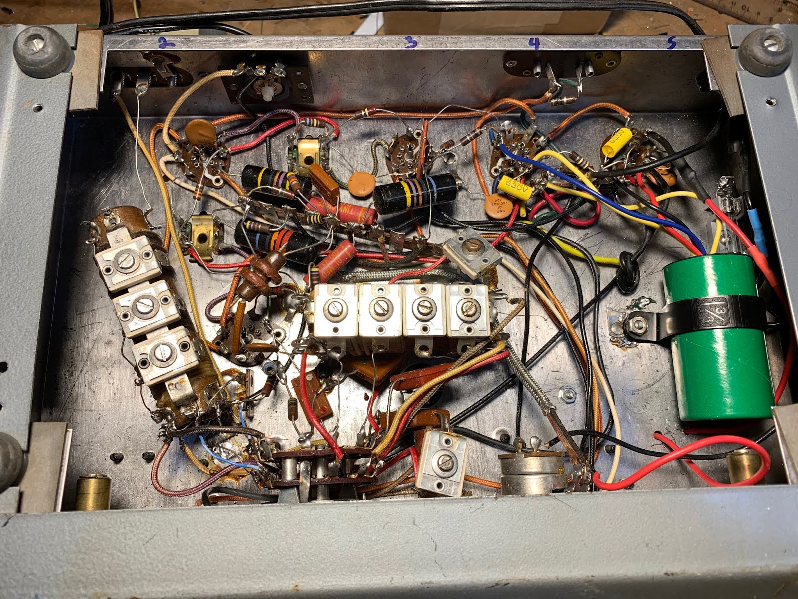
Recapping in process. Hayseed electrolytic in green can.. Old tubular caps being replaced by new yellow caps.
Recapping completed
ALIGNMENT OF THE JUNKER Armed with my newfound knowledge of how to align an S-38E, I applied this skill to the junker and was able to get it aligned without difficulty. RE-STRINGING OF DIAL CORDS On both of these S-38-Es there were dial string problems. Interestingly, both problems were with the BANDSPREAD dial cord, NOT with the MAIN TUNING dial strings. I see this as evidence that these receivers were used by ham radio operators. You don’t really need the bandspread to tune AM shortwave station, or AM broadcast band stations. But novice ham radio ops would be frantically tuning that bandspread control up and down, wearing those dial springs out. The Bandspread dial string on my Winterfest S-38E broke while I was turning it — I replaced it but it is not really smooth, so I may try again. The Bandspread dial on the junker broke also.
Broken Bandspread string from Winterfest S-38E
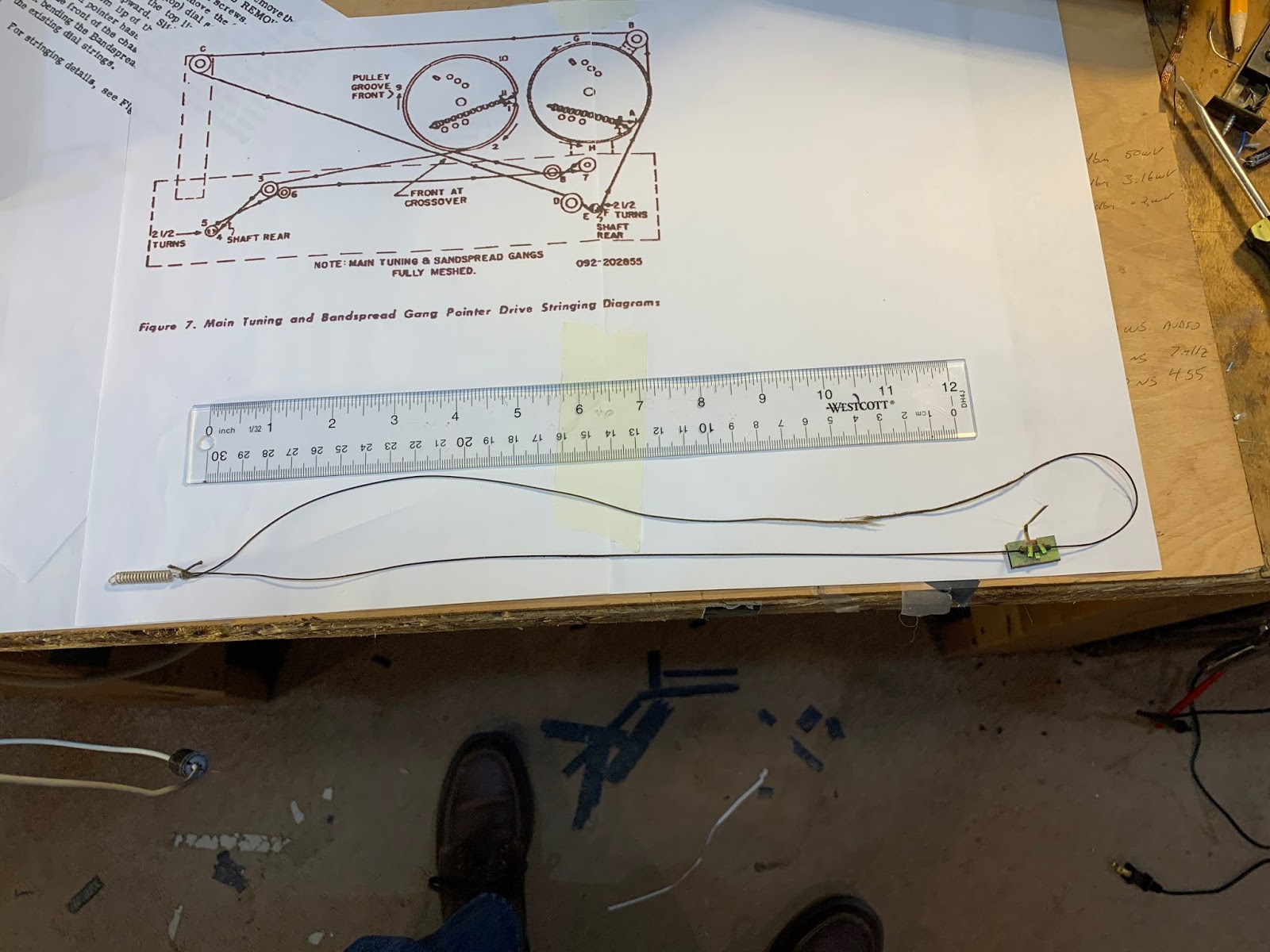
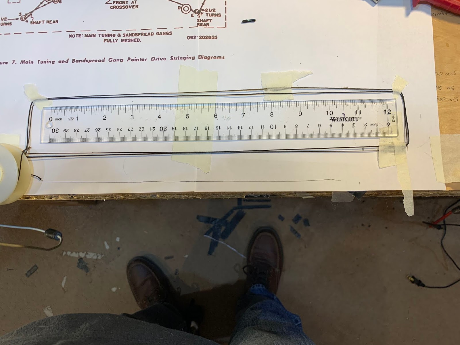
Approximating the size for the replacement string
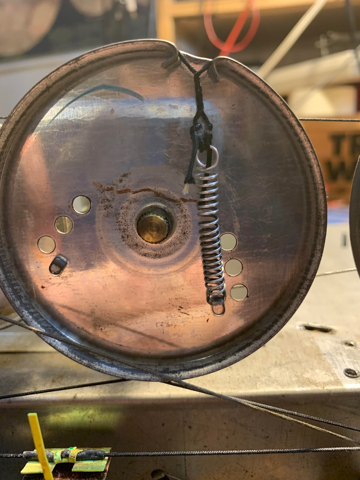
My re-stringing skills were better the second time around. Tips: use a small file to “roughen up” the spindle on the tuning knob (just the center of the spindle, so it will grab the cord better). Before installing, rub the new dial cord with an isopropyl alcohol pad, then run the string (still a a bit wet) several times over a piece of violin rosin. This seemed to prep the dial cord well. Sometimes you need a bit more tension on the string to get the tuning spindle to grip properly. Unlike the Drake 2-B, the S-38E does not have several hooks on which to attach the spring. Not wanting to have to start all over just to add a bit more tension on the string, I came up with an easier solution: Just put a few twists in the string near the spring by twisting the spring (with strings attached) around a few times. Like this:
You also need something that allows the indicator needle to grip the dial cord. I cut open a short piec of heat-shrink tubing, put it over the cord at the desired spot, hit it with hot air, then put a small dab of super glue at each end of the tubing. ( See above.) This allowed the dial pointed to grip the cord very firmly. Because you may need to move the red pointer during dial calibration (see above) I’d recommend NOT putting the drops of glue on the cord for the red pointer — you may need to slide the red one up or down a bit.
TUBES
On the Winterfest S-38E, the BFO had a very rough tone, making it impossible to copy SSB or even CW. I thought it might be a bad set of filter caps, but after I replaced them, the problem was still there. So I then replaced the tubes (warning — that 50CS audio amplifier is expensive). This fixed the problem
The junker had original Hallicrafters tubes. LISTEN! Here are some YouTube videos of the S-38Es in action:
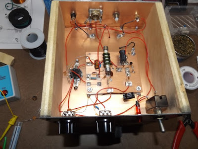
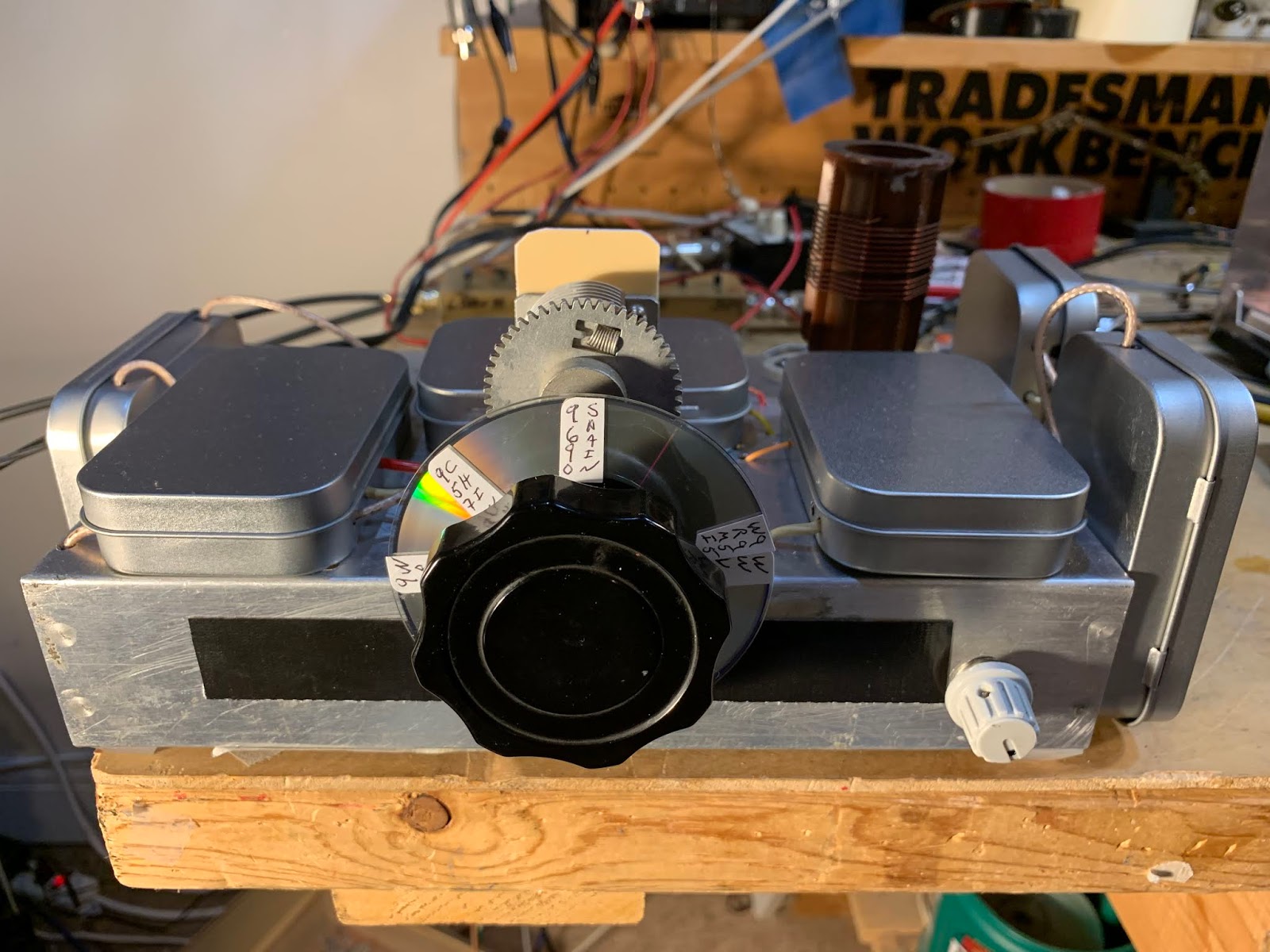
The Thing-of-Beauty above is “The Scrounger” homebrew transmitter of Jon WS1K. Jon writes:
The rig I used this morning was the Scrounger. I built it a couple of weeks ago. It took me about 2 months of trolling a local thrift store for the right pan. I wanted a pan that captured the spirit of a true Novice built rig.
As a side note, the key that I’m using is a JH Bunnell that I bought at one of the MIT flea markets last summer in Cambridge. It’s mounted on a piece of plywood and written on the plywood is the Novice callsign WN1UMD. Cool or what?
We have posted before on the amazing homebrew creations of Mike Bohn KG7TR. Today I watched this 54 minute video in which Mike describes his rigs. (Thanks to Pete Eaton, WB9FLW for pointing me to a site that has this video.)
Quote from KG7TR: “I have never destroyed a pristine Command Set.” Wonderful tribal knowledge throughout, especially on the metal work, parts acquisition, front panel work and toroid placement. Clear you schedules. This is really worth watching.
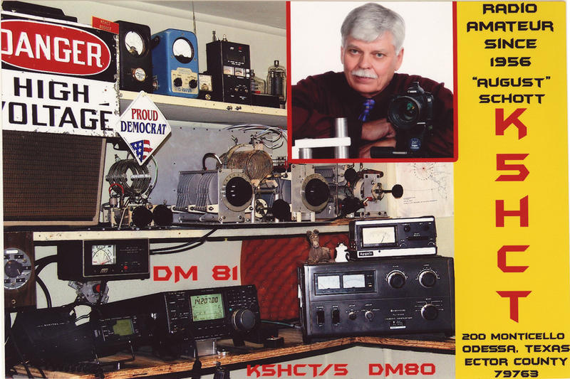
The lower portion of the column on the right-hand side of this blog is where I put links to interesting blogs, YouTube channels, and web sites. Yesterday one of the links there led me to the above video. It presents a regen receiver using one 12AU7 tube and a 12 volt power supply. Wow! I have many of those tubes. And at 12 volts I am unlikely to electrocute myself. Count me in. In the final minute or so of the video, the builder tunes around the 40 meter phone band. Suddenly I heard a familiar voice. It wasn’t recorded long enough for the callsign to be heard, but I was pretty sure it was our old friend August, K5HCT (Here Comes Texas) from Odessa. Odessa, Texas is a good skip distance from both California and Virginia, so Pete and I have both talked to August many times. When I was testing out new homebrew contraptions, August was often there to help me out. I was pretty sure it was August in the video. I checked with Pete — he too recognized the voice. Then I got an e-mail response from August — yea, it was him. On the air, I often recognize a voice before I hear a callsign. In this case it happened via a somewhat wobbly regen and the internet. THE RADIO GODS HAVE SPOKEN. Now where did I leave those 12AU7s?
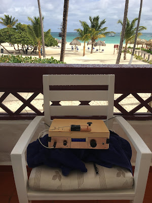
Travelogue! Dominican Republic trip. uBITX on the Beach. EFHW. LiPo Battery. First contact of the new year.
Bill’s Bench Report
Following up on proposed uBITX mods:
— Put pot on sidetone line from Raduino to keep the sidetone a bit quieter.
— Fixed the key — pounding brass
— Will install 4 States QRP Active AF filter.
— Need to reduce power on CW to 5W
— Stereo to mono headphone adapters.
— Turning off display and mic amp circuit not really worth it — they don’t pull much current.
Pete’s Bench Report:
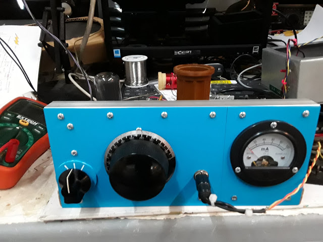
ELMAC Power Supply project
1930s era transmitter?
Teensy and SDR
PETE’S IDEA ABOUT GETTING LSB AND USB FROM BITX40
KWM-2 suggestions
Back to Bill’s Bench:
Working on HRO-ish Receiver.
Bad SBL-1
Got idea for wider ceramic filter from Paul VK3HN
Ordered parts from Mini-kits in Australia. They sent 6kc filters.
Bruce KK0S sent me some 10 kc filters too.
Installed 6 kc filter with L network matching networks. Works great.
Also installed Infinite Impedance Detector that Paul used.
Needed some additional amplification ahead of the IID, so I used one stage of BITX amp.
Works great. I can tune full 40 meter band AND 49 meter SW band. Radio Romania, China, Radio Marti, Brazil, South Carolina.
Beefed up the shielding to cut down on AM detection.
MISCELLANY
— AM and DSB in LTSpice
— Duly Noted: Paul VK3HN’s RIG: “THIS MACHINE KILLS KILOWATTS”
Kanji YC3KNJ’s QRPesso Expresso Coffee in the field
— The DANGERS of powerful magnets.
MAILBAG:
–KK4DAS Dean doing great things. MMM heard at Penn State. Where is the rest of the CBLA?
— Thanks to Don for kind donation to the SolderSmoke cause
— Dale BA4TB — First SolderSmoke feedback from China. Thanks Dale!
–Steve Silverman: Sideswipers and bugs were made to handle “carpal tunnel of the day” So do I need a keyer for casual CW work?
— Peter VK8VWA on the limited knowledge gained from kit building. Listens to podcast while walking on the beach in Australia.
— Allan Hale — Clothes Pins as Toroid holders. Yes! More Clothes Pins Wild Woody Keys from Dave Ingram
— Pete WB9FLW 100 Watt Amp from WA2EUJ
— Dave Wilcox K8WPE A medical question: Does the Michigan Mighty Mite work differently depending on what kind of medicine was in the pill bottles used for the coil form? Good question Doc! Dave suggest that putting CBD on the coil or the crystals. Anything to mellow out the ham bands…
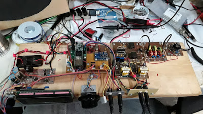
Pete’s Plank SDR When you know stuff, you can do stuff!
I cringed when, at about the 32 minute mark, during a discussion of the moral necessity of preserving old gear, Michael appeared on the screen with a Heathkit Q multiplier sitting right there next to him. It was as if he was talking about me. I felt as if I had been hauled into Ham Radio Court, Judge Michael Murphy presiding.
I have already REPEATEDLY admitted to sacrificing MULTIPLE Q MULTIPLIERS. But I did it for good reasons: 1) I have some objections to use of regeneration, especially in superhet receivers. After all, Armstrong created the superhet in part to free us from the tyranny of regeneration (that he had also invented). 2) This is a case where the parts ARE greater than the sum. Specifically that variable cap WITH reduction drive. And that perfectly sized metal box. Those capacitors are currently in service in at least two of my homebrew SSB transmitters. And as I look around the shack, I see one of those boxes housing an Si5351 VFO, and another holding the dual-digital frequency displays for my DX-100/HQ-100 AM station. 3) Mike notes that these Q-multipliers are being sold for TWO DOLLARS at hamfests. At prices like this, temptation is just too strong. So I plead guilty, your honor. But I ask the court to consider the circumstances under which I dismantled this obsolete gear, and the good uses that I made of the parts that I obtained. Also, I’d like to make note of the fact that I salvaged from a junk pile a Heath VF-1 (I completely rebuilt it) AND I restored to usefulness a Heath DX-40 — both these devices appeared in the WU2D video. Finally, if anyone really needs the remaining parts from the now deceased QF-1s, I’d be willing to donate them (in an effort to redeem myself). Thanks Mike!