Could Grayson’s Arduino Thermatron Shield Protect Us From Digi Domination?

Something old, something new, eh Grayson? The author of “Hollow State Design” is engaged in an (I suppose) admirable effort to bridge the gap between our beloved Thermatrons and those new-fangled Arduinos. Here Grayson tries to explain and justify his flirtation with the dark side:

I want to do some experimenting with Thermatrons and Arduino. Sound weird? Maybe not.

I really like playing around with the Arduino even though it violates my ban on digital technology in my shop. (My excuse is I am trying to use it teach my son something he can use to get a job someday.)

Sure Grayson. That’s what they all say. “I was doing it for the kid…”

Kidding aside, that tube shield looks pretty cool. And I like the MeTubes base for the Thermatron.

HEAVY METAL! How to Handle HEAVY Boatanchors — And Which is Heavier: R390 or DX-100?


Grayson:

I was on 40 AM today and I mentioned to the guys your thoughts about the possible need for a block and tackle and a metal beam in your shack roof to help you deal with your R-390A. They sympathized completely. One fellow claimed he knows hams who are working out with weights just so they can handle their boatanchors. Another guy said he is thinking of building a small crane, perhaps powered by his chain saw (yikes!). A third fellow said he actually bought a thing called a “lifting table” from Harbor Freight.
This got me to thinking: How much do those R-390s really weigh?
A MERE 85 pounds! That’s it? Holy cow, the DX-100 has a listed shipping weight of 120 pounds!
73 Bill
Bill:

Nice thing about a “regular” boat anchor (DX100, HT37, SX101, etc.) is that you can put it on its side and get fairly easy access to both sides, and all the components at once. The problem with the R390 (and a lot of Collins military gear) is Collins worked hard to cram so much in a “small” space that you have to take whole sections apart to get at anything. So you have to “flip” the chassis over, side, over, on its back, etc. UGH. To get at the RF front end components, you gotta take the front panel off before you can remove the RF chassis. UGH
I know about the lifting table from harbor freight. A really nice shack accessory. Puts the rig at a better height to work on. With a “lazy susan” thing on top, a nice arrangement! Maybe next Christmas.
73, TA2ZGE


Grayson
TA2ZGE – Ankara, Turkey
KJ7UM
Follow the Hollow-State Design Blog


Sputnik Replica Transmitter, an “Error” in the Sputnik Schematic, and Why 20.005 MHz?

Mark K6HX pointed me to very interesting Hackaday article on Frank PA3CNO’s Sputnik transmitter replica. As blog readers will recall, we went through a period of Sputnik-mania a few years ago: http://soldersmoke.blogspot.com/search?q=sputnik Chief Designer Comrade Mikhail Rainey AA1TJ sent me some of the Russian tubes (like those pictured above).

The Hackaday article pointed to our post reporting that Oleg RV3GM had found the schematic:
http://soldersmoke.blogspot.com/2013/04/sputnik-schematic-found.html Stefan reports that PA3CNO found “an error” in the original Soviet schematic:
http://www.radio.cc/post/Franks-power-supply-for-sputnik A mistake you say? HAH, I say! Hah! This must have been part of a sinister commie plot to prevent the capitalist imperialists from ever being able to reproduce the glorious transmitter of the Soviet people. They almost succeeded.

Just kidding.

In the course of looking through our old Sputnik posts, I came across a question I posted:

I have a question: OK so the crafty Soviets picked 20.005 MHz for some good reasons: Being so close to the WWV freq, it would be easy for hams and SWLs to find it with precision. In the November/December 2007 issue of “Break In” (from NZ — thanks Jonathan-san!) ZL3DW notes that this frequency selection would allow a receiver set to exactly 20 MHz to “produce an audio tone plus or minus the Doppler shift without ever going through zero beat.” But zero beat with what? Most of the receivers out there would not have had BFOs, right? So the Soviets wouldn’t have been using ordinary CW, right? Were they using AM, with the beeps produced by an audio oscillator modulating the carrier?

Was their diabolical plan to use WWV as the BFO for those using ordinary AM SW receivers? If so, a 5 kHz separation from WWV seems to be too much right? Especially when the Doppler shift on approach would push the frequency up a bit. Maybe they just chose this freq to make it easy for listeners to find — just a bit above WWV. Comrade Rainey surmised that they were keying the PA stage — the oscillator “backwave” was at times audible on the ground.

What do you think Comrades?
DSW and 73.

Design Wisdom from Allison, KB1GMX

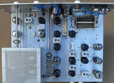
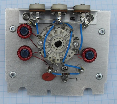
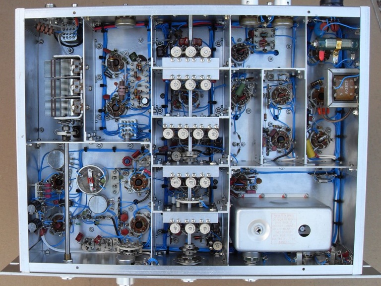
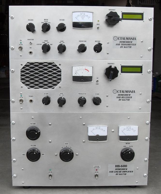
Allison KB1GMX has helped me out of numerous battles with recalcitrant amplifiers. She provided an interesting contribution on the r2pro mailing list thread that I referenced yesterday:


Interesting thread…

I see Rick as having provided the basis and tools and it up to the collective ‘US” to use them to
create that next generation radio. All you have to do is decide the performance and
then go about looking at the means to do so. All the blocks are there.

Dynamic range, how much is enough? When I’m portable or mobile raw sensitivity is
more useful as the antenna is usually a compromise. Overload is easy to handle with
switchable attenuator. The exception to this was a radio designed for contesting in a
hostile environment (a KW user 800ft away) if you burn power you get overload
performance. Its not a battery friendly radio (RX power is over 1A for headphone output).
Look at what you need and not what you want.

TX power is just adding stages. I’ve worked MOSFETs, LDMOS, GaN FETS and there
are some pretty cool devices out there and some not designated for RF are cheap.
If all else fails the IRF510 gets both raves and derision. At 12V its a tepid device
but at over 20V and at 24V it starts to wake up and really perform. I’ve run The WA2EBY
design for a few years at 45W level using two of those push pull at 28V and its clean and
solid and the original pair are now over 6 years old! I also run 8 of them (4x4push pull)
at 32V at 6M for a cool 210W with good IMD. I’d add all the good (high gain, low IMD)
power fets perform better at 28 or 50V. For those into CW consider class E as I’ve
worked with this and using GaN fets have generated 15W with 82% efficiency at
13.56mhz (includes driver and osc) and using the lowly IRF510 at 12V a full 10W
with 85% efficiency. Class E can be amplitude modulated.

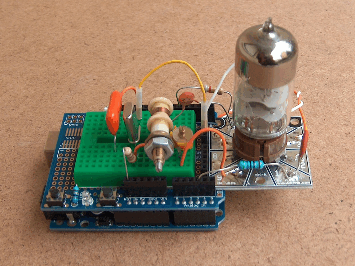
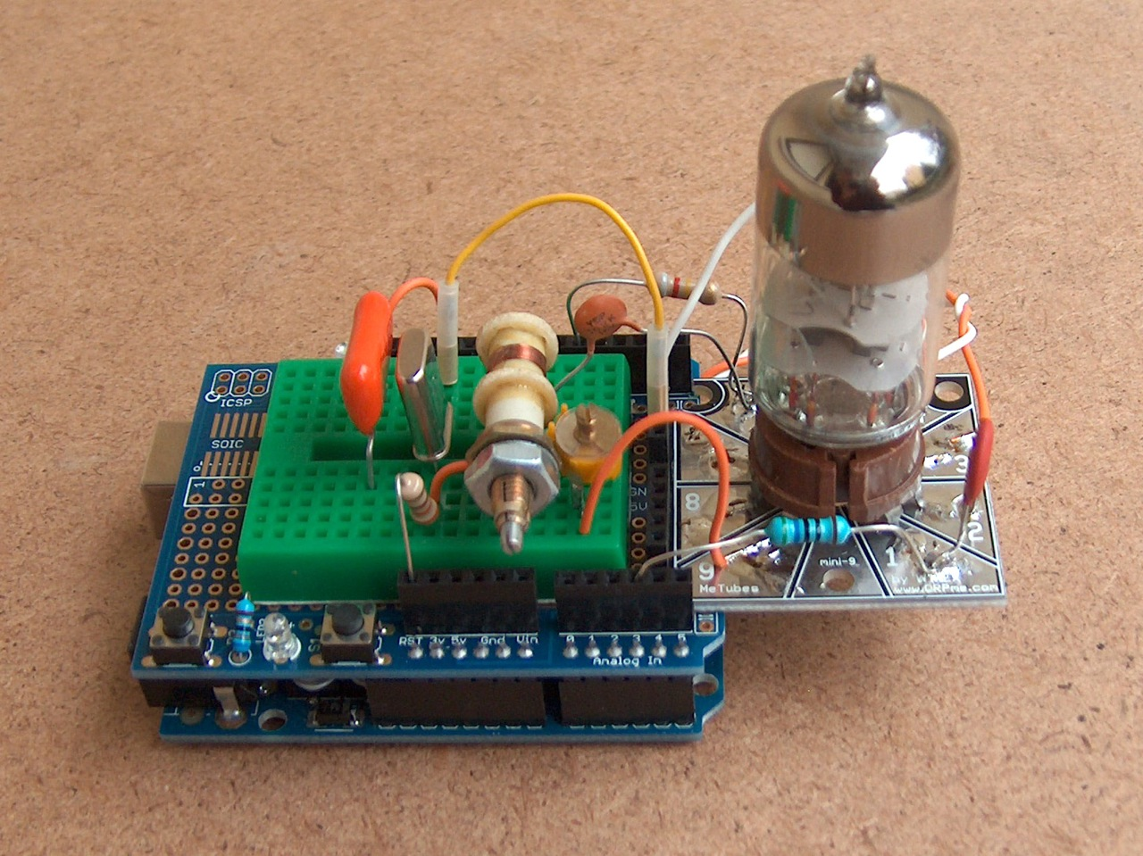
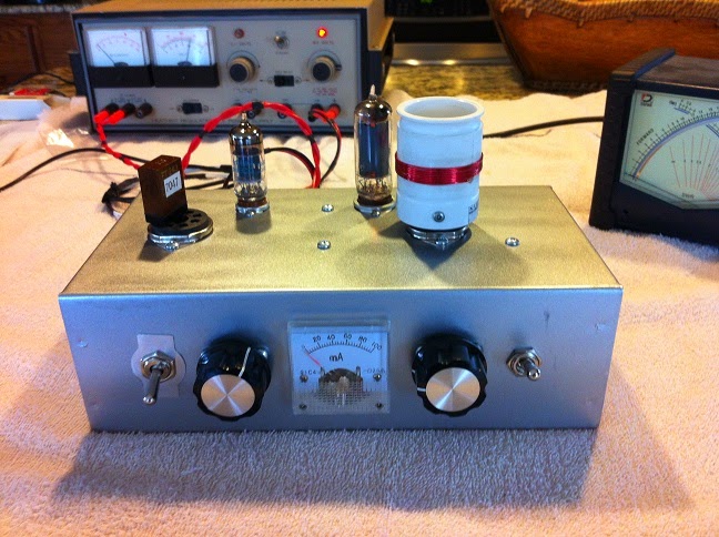
As to the thermionic FETs, a 6AU6 crystal osc driving a 5763 for 10W gets a lot of raves
on 40M from a buddy that runs CW. The same deal plate modulated can sound good
at 5-6W AM on 75M. For those that want more a 6C4, 6aq5, 6146 will get you over
50W on CW and 25W AM. Change the bias a little and inject IQ SSB into the driver grid
and be running 50-80W PEP. A 12BY7 or 6CL6 driving a pair of 6146 will get you into
the 180-200W DC input range for about 100W. Remember the hybrid radios solid state
low level and rugged tubes for the heavy lifting. The Pi network (or Pi-L) will load anything
from about 28 to 100ohms more if you use enough taps and variable caps. That and DC-DC
converter for the HV are not terrible at 80% or better (even the 1960s transistor designs
were better than 75%).

In the end it all starts with the receiver. For that you can always start with a 1T4 RF and
a 1R4 converter and a 1T4 as regen driving a 3V4 audio. Power it with 45V (five 9V battery)
and a C cell and go portable. It should run for a very long while. Hollow fets run well at low
drain currents. 🙂

Allison

N8NM: Thermatron Meets Silicon (Part II or III)

Steve N8NM has been pushing the limits of radio hybridization. In this receiver he has 12AX7 thermatrons running alongside an Arduino and a Si5351. Somehow I find this both very appealing and deeply disturbing. Many of you will know what I mean. But FB Steve — keep them coming. Put these unique rigs on the air and strike a blow against the Yaesu-Icom-Kenwood monotony!

Bill:

Here’s a pic of a Thermatron-Meets-Silicon receiver that I’ve been working on. Tubes are 12AT7 mixer, 2x6BA6 IF amps, 2x12AX7 (product detector, AGC amp and 1st AF) and 6AQ5 audio out. An Arduino controlled Si5351 provides the LO and BFO as well as handling all of the switching, and the mixer and product detector use variations on Dr. Pullen’s dual-triode circuit. I’ve had this one on the air, but the hardware and software still need some, um, refinement. And painting the panel has to wait until spring as my XYL doesn’t share my affinity for paint fumes.

73 – Steve

TIA-Tube Hybrids from Steve N8NM (Part 1)


Last week Steve sent us a picture of his Straight Key Night rig which consisted of a homebrew thermatron transmitter and a TIA BITX as the receiver. I asked Steve for more info on the TIA BITX.

Bill:

Shot these right after making the first QSO using the TIA rig as the receiver. The Arduino and ‘5351 are still on a breadboard, otherwise, all of the PCB modules except the filters and PA are installed on the chassis.

The QSO was uneventful, which is a good thing!
73!
Steve

N8NM’s Straight Key Night Rig

Hi Bill,
Just wanted to drop you a line to let you know that I’ve recently discovered your SolderSmoke podcasts and am enjoying the heck out of them! In fact, you and Pete have inspired me to break away from the thermatrons and delve into the wonderful world of the TIA transceiver, and after several weeks of sniffing rosin, my new rig is now receiving signals without the aid of any external life support! It’s still a bit haywired, but I’m looking forward to pairing it with my little 6AG76L6 transmitter for a few SKN QSOs tomorrow.
I haven’t taken any pics of the new rig yet, mainly because, at this point, there’s not much to see, but here’s it’s little octal-based friend with its AD9850/6AG7 hybrid VFO (works a bit better than the VF-1 that it replaced J):
Anyway, thanks for putting forth the time and effort to do the podcast! All the best to you, Pete and your families in the new year.
73,
Steve Murphy, N8NM

The Pleasures of AM, and The 807 (Truly a Bottle Worthy of the Gods)

Sometimes a message posted in the comments section of the blog is so good that it needs to be raised up and converted into a posting all its own. Such is the case with a message that Rupert G6HVY sent us last month about AM and old rigs. 60 meters eh? Hmmm…


Rupert wrote:

It’s always a pleasure to listen to AM QSOs, which hereabouts seem to be mostly on 80 and 60. I bought an FM board for my FT-101ZD with the intention of getting some 10m action, but now I think I’ll leave the AM board in (you can’t have both) for when I get the beast out of storage. AM, even AM that hasn’t been optimised for beautiful audio, sounds so much nicer than SSB.

The other side of AM is to get old military rigs up and running, which is quite the opposite to the golden voice crowd. Another project waiting for time and energy here is an RCA-built Wireless Sets Number 19, which can put out ten watts or so of AM from its 807 (truly a bottle worthy of the gods) – and of course, there are infinite numbers of 50s and 60s vintage thermionic projects in the contemporary magazines. It would be particularly satisfying to find the original PSU for that, as it has two Dynamotors to convert the 24V DC supply to HT, with the transmitter one cutting in when the PTT (sorry, pressel switch) is hit. I say cutting, it actually runs up to speed over a couple of seconds, giving an original 19 Set a very distinctive slow fade-in at the start of an over. Hearing one of those crackling away on 5 MHz is utterly delicious.

Rupert, G6HVY

Octalmania — KG7TR’s Amazing Thermatron Rigs

Grayson in Turkey alerted us to Mike’s homebrew rigs:

Bill, Pete:

German Thermatron Homebrew

Michael DF2OK has been melting solder in Germany. Above is a short video of the first sounds made by an AC-1 replica he built. Michael notes: “Yeah, I love these old style radios. You can see nearly everything. 🙂 BTW: All without Arduino and other black boxes and chips!”
FB Michael.

During the AC-1 build Michael struggled with a bad tube. His discovery and resolution of the problem is presented in this video (understandable even to those who don’t speak German):

Finally, here is a nice video of Michael’s 40 meter regen receiver. Anyone who has built or worked with a regen will understand perfectly this video. Watch Michael tune in stations while adjusting the regeneration. Note his demonstration of the lack of hand capacitance. FB Michael! Thanks!

Alan Re-Caps His Drake 2-B

That Drake 2-B is a beautiful thing. Every time I look at an older tube rig I’m reminded of the three dimensionality of these old machines. Solid-state rigs are in Flatland, but tube rigs are in three dimensions.

Alan makes a very cool use of the I-pad in this repair. And I’m jealous of his Hayseed Hamfest Electrolytic (I opted for the multiple caps hanging below the chassis). Excellent management of the solder-sucker by Alan. And I was impressed by the disciplined way he pulls solder from the reel — he has the reel right next tot he rig and dispenses it directly. I tend to hack off small lengths of solder and end up with lots of little bits of solder on the bench.

Glad to hear that the other caps on the Drake are standing the test of time. I wish the same could be said for all the caps in my Heath HW-101.

One thing caught my eye in Alan’s video: The dial cord. You know you have become a true 2-B aficionado when you have actually gotten good at replacing the dial cord. It is something of a rite of passage. Perhaps this will serve as the basis for a future video by W2AEW,

Thanks Alan! And congrats on passing 4 MILLION YouTube views. People watch because your videos are so good.

Our book: “SolderSmoke — Global Adventures in Wireless Electronics” http://soldersmoke.com/book.htm Our coffee mugs, T-Shirts, bumper stickers: http://www.cafepress.com/SolderSmoke Our Book Store: http://astore.amazon.com/contracross-20

Rigs vs. Radios: A Real RIG in a Real SHACK

Earlier this year Pete and I were talking about the use of the word “rig.” For me this is a hallowed term that captures much of the essence of ham radio. Sadly, in modern parlance “rig” seems to be increasingly substituted by word “radio.” If you are wondering what the difference is, well, I think this video presents a good example of a rig.

There was a nice exchange of e-mails on QRP-L about this video:

Jun 2 at 9:54 PM

Our book: “SolderSmoke — Global Adventures in Wireless Electronics” http://soldersmoke.com/book.htm Our coffee mugs, T-Shirts, bumper stickers: http://www.cafepress.com/SolderSmoke Our Book Store: http://astore.amazon.com/contracross-20

Hank’s New Rig


Pete, Bill:
Applied power to the 6C4 / 5763 transmitter for the first time today. I made RF. No smoke was released to the wild. Only issue is the load air variable cap is fully meshed at full capacitance and still not getting the dip on it. Need to root in the junque box for a 220 or 330pF silver mica and wire that in across the load cap.

As it is its putting out 2w. Listening on a general coverage receiver I’m not hearing any chirp or drift. Will build a low pass filter and have to interface in the power supply. Still have a few details to do such as labeling the controls but for the most part I just built a transmitter from scratch. Happy day at the workbench.
Another fix is to redo the coax from the RX / TX switch. Didn’t have any RG174 so I just grabbed a clipping of RG8X had laying around. Ugly but got the job done.
Thanks for all the help and encouragement.
Till later
Hank Ellis K5HDE

Our book: “SolderSmoke — Global Adventures in Wireless Electronics” http://soldersmoke.com/book.htm Our coffee mugs, T-Shirts, bumper stickers: http://www.cafepress.com/SolderSmoke Our Book Store: http://astore.amazon.com/contracross-20

Who is this earnest young radio amateur?

Name that ham! Here are his comments:

This is vintage early 1960’s and my call sign at that time was K3???. One of my favorite rigs was the Johnson Adventurer which I built and had a 6AG7 driving an 807 –50 watts input. On the top shelf near the lamp is the screen grid modulator for the Adventurer. I was in tall clover.

On the bottom opening is a 40M CW transceiver I built it had a 6CX8 MOPA—about 5 watts. The RX was a two tube regen.

Our book: “SolderSmoke — Global Adventures in Wireless Electronics” http://soldersmoke.com/book.htm Our coffee mugs, T-Shirts, bumper stickers: http://www.cafepress.com/SolderSmoke Our Book Store: http://astore.amazon.com/contracross-20

Tube Transmitter in a Cuban Cigar Box

Beautiful use of a cigar box by Ben, KK6FUT. Ben is working in close proximity to Pete N6QW and has obviously fallen under the influence of Pete’s “Build Something With Tubes” field.
Watch out for the high voltage Ben. You aren’t in Arduino-land anymore! One hand behind the back OM!

Our book: “SolderSmoke — Global Adventures in Wireless Electronics” http://soldersmoke.com/book.htm Our coffee mugs, T-Shirts, bumper stickers: http://www.cafepress.com/SolderSmoke Our Book Store: http://astore.amazon.com/contracross-20

Dear Santa: I want a Knack Watch. The one with real tubes…

This is what all the cool homebrewers will be wearing next year. Just be careful at airport security — they might not understand!

Check it out: http://www.johngineer.com/blog/?p=1595

We received some comments from some noted Thermatron authorities:

Hi Guys,
This will cause all of the bells, whistles and sirens to go off all it once.
Now all that is needed is a logo on the watch that says
EBOLA ( Electronic Bi-state Operational Long Arithmetic) and this will cause you to go to jail without passing Go or collecting $200.
Pete


———————

Wow, I love this thing!…even though it uses little black plastic things to work. Have no idea what they are. (johngineer has knack squared)

Reminds me of a project I am trying with fellow ham. We picked up an old HP nixie tube freq counter at junk yard. We were going to strip out the nixie tubes to make a clock, but decided we could make it as clock as is. Want to program an Arduino thing into generating a frequency that is the time and feeding it into the counter.
For example 3:45:25 would be 34,525 Hz.
But my Italian is terrible so haven’t been able to get the Arduino to work. Just learning it. Project a bit over my head. picked up one of those online language courses on Italian. Hard, but not as hard as Turkish!
Grayson
TA2ZGE – Ankara, Turkey

KJ7UM
Follow the Hollow-State Design Blog


———————–

I’m wondering if I could do it Manhattan style, with discrete components…

Our book: “SolderSmoke — Global Adventures in Wireless Electronics” http://soldersmoke.com/book.htm Our coffee mugs, T-Shirts, bumper stickers: http://www.cafepress.com/SolderSmoke Our Book Store: http://astore.amazon.com/contracross-20

Kiwi Lunchbox Sideband: The Tucker Tin Two

Pete Eaton sent us links to an old article from the New Zealand magazine “Break-In.” So many good, simple rigs come to us from New Zealand! Who can forget ZL2BMI’s DSB rig? This one is the work of Fred Johnson ZL2AMJ. It is especially interesting and is in some ways similar to Peter Parker’s “Knobless Wonder.”

It uses the phasing method of sideband generation. No crystal filters in this one. You need TWO balanced modulators. You have a 90 degree phase shift network for the RF (from the carrier oscillator) and a second 90 degree phase shift network for the AF from the mic amplifier. When you combine the signals from the two balanced modulators — viola! — one of the sidebands disappears. The balanced modulators take care of the carrier, and an SSB signal is launched. That is how my old HT-37 works, and similar ideas seem to be at work in modern SDR rigs.

G3TXQ has the complete set of Break-In articles (it includes a VFO):
http://www.karinya.net/g3txq/temp/tucker_tin/

Here is a Canadian article on the rig. A “Tucker Tin” is apparently what the Kiwis call a lunch boxes (shades of Benton Harbor…).


Thanks Pete!

Our book: “SolderSmoke — Global Adventures in Wireless Electronics” http://soldersmoke.com/book.htm Our coffee mugs, T-Shirts, bumper stickers: http://www.cafepress.com/SolderSmoke Our Book Store: http://astore.amazon.com/contracross-20

SSB with Just Two Tubes

Here is the two tube SSB transmitter that Pete was telling me about. This would be a nice companion to the “Mate for the Mighty Midget” receiver that I built a long time ago. Another Benton Harbor Lunchbox may have to be sacrificed…

Our book: “SolderSmoke — Global Adventures in Wireless Electronics” http://soldersmoke.com/book.htm Our coffee mugs, T-Shirts, bumper stickers: http://www.cafepress.com/SolderSmoke Our Book Store: http://astore.amazon.com/contracross-20

Eclectic Electronics: Powering Arduinos with Tube Filament Voltage

You know that you are dealing with a broad range of technology when you find yourself discussing how to power an Arduino microcontroller from the 12V AC voltage on a vacuum tube filament line. Thanks Pete.

Hi Bill,
There is only so much that can be said in 1 hour and 19 minutes so maybe here is some stuff for the blog.
The 1st thing on the list when working with the Arduino when it is not connected to the computer is to have a proper power supply. My research as indicated that 9 VDC “raw” is a good starting point to power the Arduino boards so here are two supplies that will provide that power.
I did find that it was necessary to have an isolated supply when working with the “toob” radios and even to isolate the RF into the radio using a ferrite core transformer –some more tribal knowledge.
One supply takes an 8 VDC regulator and boosts its output to 9 VDC. The second uses a switching regulator and the beauty of the second is that the input can be either 12 V AC or DC. This is ideal for use in toob radios where you can sample the 12.6 VAC filament string.
73’s
Pete

Our book: “SolderSmoke — Global Adventures in Wireless Electronics” http://soldersmoke.com/book.htm Our coffee mugs, T-Shirts, bumper stickers: http://www.cafepress.com/SolderSmoke Our Book Store: http://astore.amazon.com/contracross-20