Overheard at Dayton: Drake 2B Market Manipulation! (& Help needed with 455 kc IF can)


I received a very nice message from Preston Douglas. Conveniently, he is an attorney, and I have asked him to stand ready to defend me in court should I ever be accused of manipulating the markets for Drake 2-Bs (and perhaps the market for SSDRAs).

Can any out there help Preston with his SX-110 455 kc IF can?

May 20 at 3:38 PM
Hi Bill,

I enjoyed #160, even though I heard those talks, live at FDIM.

I thought you’d be amused by what I overheard in the flea market on Saturday in Dayton. I was looking at a Drake 2B and Q multiplier being offered by a lady who said they were her father’s. They looked to be in pretty clean shape, though of course there was no way to know what was going on under the hood. She was asking $200 for both, and said she was open to reasonable offers. Now, I already have a 2B and haven’t found any need for the Q multiplier. And I had flown out to Dayton from NY, so would have had to ship the pair of boxes home–probably should have bought them anyway and sent them home by UPS for that kind of money.
Anyway, there were two other guys looking at the 2B. One said to the other that these were among the best receivers of the tube era, but that the prices had become inflated by this guy who does the Soldersmoke podcasts talking up the virtues of the 2B. Couldn’t help smiling at that.
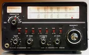
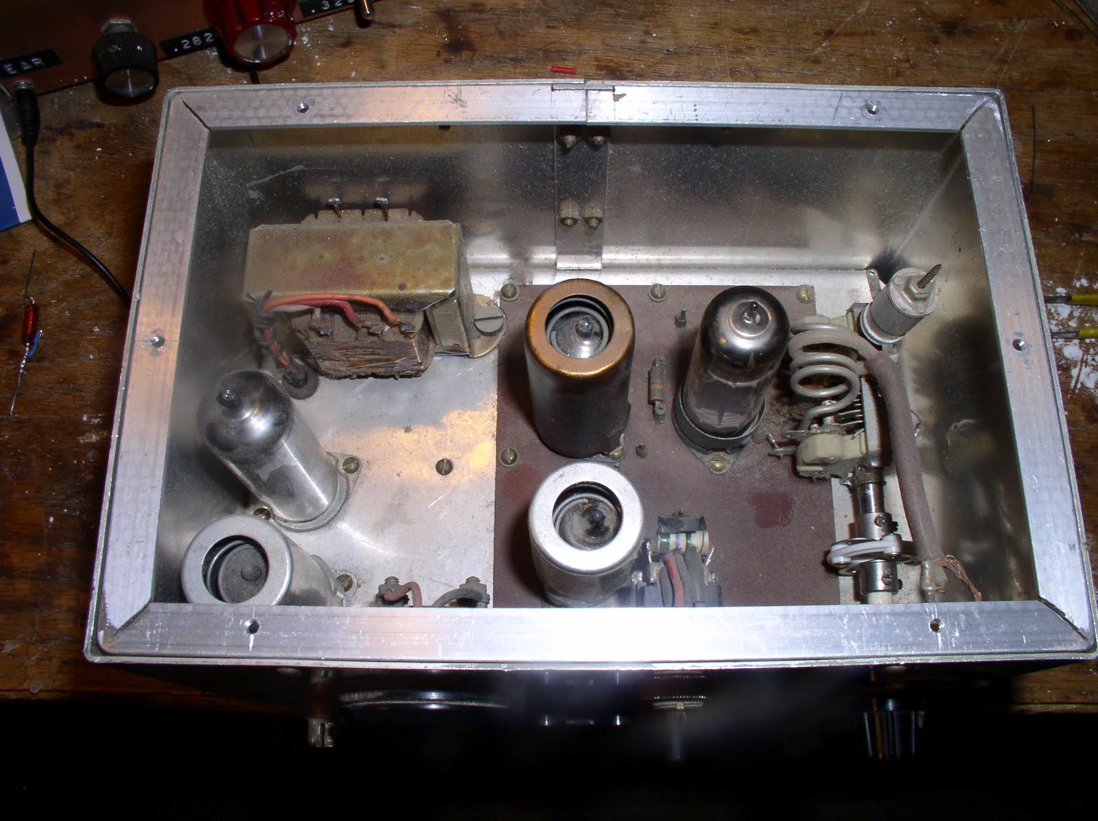
As to the Hallicrafters SX-110 on the repair bench. Well, I worked out a deal with a professional tech guy to trade him my non-working HP 8640b sig gen for some bench time on the 110. He found that the first IF transformer that I was having so much trouble aligning was non-working. He had no replacement, so he bypassed the whole transformer with a cap to get signal to the next stage. This is, of course, not a satisfactory solution. And nobody has that IF can to sell. I did read on another radio repair guy’s web site that he, too, usually stops working on a set with a bad IF can because repair is so labor intensive.
Frankly, I don’t accept that. I mean what’s inside there? A couple of coils and some open silvered mica leafs. So, I plan to remove the can, open it, and fix it. According to the Internet, the built-in caps on these cans become defective and need replacement by modern capacitors. Or, maybe a wire is broken off. Before I do anything, I am going to see if that transformer is really unable to peak at 455. Anyway, maybe I’ll get some time to mess with this radio over the holiday weekend.
One of the guys (or was it you?) recently said he builds ’em, makes a few contacts to prove they work, and then puts them on a shelf. Then he builds another one. It’s like that sometimes.
PRESTON DOUGLAS

Our book: “SolderSmoke — Global Adventures in Wireless Electronics” http://soldersmoke.com/book.htm Our coffee mugs, T-Shirts, bumper stickers: http://www.cafepress.com/SolderSmoke Our Book Store: http://astore.amazon.com/contracross-20

Herring Aid Motorboating STOPPED!

FIXED! Following up on suggestions from Tony Fishpool and from Roy Morgan, I put a 10 ohm resistor between the two supply lines and put 100 uF caps to ground at either end of the resistor. I can now operate the receiver at high AF gain (no problem running a speaker) without the KLUDGE of two power supplies. The RX sounds great. I will soon match it up with the equally awesome Tuna Tin 2 for 1976 QRP EXTRAVAGANZA.

Our book: “SolderSmoke — Global Adventures in Wireless Electronics” http://soldersmoke.com/book.htm Our coffee mugs, T-Shirts, bumper stickers: http://www.cafepress.com/SolderSmoke Our Book Store: http://astore.amazon.com/contracross-20

Stopping the AF oscillations in the Herring Aid 5

Thanks to all who responded. This morning I got a significant clue: Following up on Tony Fishpool’s suggestion, I separated the power supplies: I ran the RF amp, oscillator and mixer base bias off a small 12 V battery, with the mixer collector circuit and the AF amps running of the bench 12V supply. The AF oscillations completely stop under these conditions. So the feedback is probably taking place via the 12 V supply lines. 73

Our book: “SolderSmoke — Global Adventures in Wireless Electronics” http://soldersmoke.com/book.htm Our coffee mugs, T-Shirts, bumper stickers: http://www.cafepress.com/SolderSmoke Our Book Store: http://astore.amazon.com/contracross-20

Direct Conversion Receivers, AF Transformers, and Motorboating

The Herring Aid 5 is a direct conversion receiver (scroll down for details). It is a minimalist design from 1976 using parts available at Radio Shack stores. One of the parts no longer carried by Radio Shack is a 10K-2K ohm audio transformer. Following NORCAL’s 1998 design update I ordered an equivalent Mouser part (Xicon 42TU002-RC). I had been running the receiver with simple RC coupling instead of the transformer.

Yesterday the Mouser part arrived and I put it into the circuit. An increase in AF gain was immediately apparent, but the thing went into AF oscillation as soon as I turned up the AF gain.

I tried beefing up the AF decoupling. But I think the real problem is just the presence in the middle of the board of a rather large (1 inch x 1 inch) audio transformer. I moved it around a bit to get it away from the toroid of the preceding stage. This helped a bit, but it still breaks into oscillation if I turn up the AF gain.

Any suggestions? Or is this just part of the minimalist 1976 lifestyle?

Our book: “SolderSmoke — Global Adventures in Wireless Electronics” http://soldersmoke.com/book.htm Our coffee mugs, T-Shirts, bumper stickers: http://www.cafepress.com/SolderSmoke Our Book Store: http://astore.amazon.com/contracross-20

Some notes on the Herring Aid 5


Sure, this receiver is not “state of the art.” But that’s the whole point. I wanted to finish the receiver project that I couldn’t finish back in 1976.

I tried to stick as close as possible to the original design and parts. NORCAL came up with an updated schematic in 1998 with parts that are more readily available. But Designer Jay Rusgrove was shooting for something that could be built with all the parts coming from Radio Shack. I think that is probably one of the factors that attracted me to the project way back when. That’s why Jay went with varactor tuning (no hard-to-get variable caps!). And that’s why he used coils that were wound on Radio Shack 10uH RF chokes (no need for hard-to-find toroidal cores). In this sense there is some common ground between the BITX rigs and the Herring Aid 5.

I stuck with the RF-choke as a coil idea for the VFO, but went with the NORCAL-prescribed toroids for the front end and mixer coils. (I may go back and try to use chokes in these circuits, but I’m not sure my junk-box will yield the kind of RF chokes that Jay used).

I wish I had known a few things when I was building this back in 1976: More knowledge about how to wind the coils would have been a big help. I wish I had realized that I could use a SW receiver to get the oscillator on the right frequency. I guess this was in the days before Ugly and Manhattan building techniques, but it would have been nice to know that there was no need to actually etch a board for this project (I did!).

The coils really are a bit tricky. Jay didn’t use any trimmer caps, so I guess you had to just hope that the front end coil and cap resonated somewhere near 40 meters. As for tuning the oscillator, Jay recommended scrunching and un-scrunching the turns on the RF choke. Yikes! Give me some trimmer caps!

I also found that you have to watch the level of the RF going from the oscillator to the mixer. Too much, and the receiver is deaf. Too little, same result. You need to experiment a bit with the number of turns on the pick-up coil from the oscillator.

The warnings about the pitfalls of that single BJT mixer were right on the mark: Lots of AM SW breakthrough. But I kind of like the background music. Strong RFI from local FM broadcast stations was another story (WMZQ is a country music station!). I reached into my junkbox and found a low-pass filter from a Heathkit DX-60. I just put that between the antenna and the receiver and the country music was GONE!

I really love this little receiver. I have it playing 40 meter CW as I type. It sounds great. I feel the urge to built a Tuna Tin 2 and put both of them on 40.

In the original Tuna Tin 2 article, Doug DeMaw notes that Jay Rusgrove was thinking of doing a companion receiver and says that he was thinking of calling it the “Clam Can 5” ! There were jokes about receivers for hams with “tin ears” and about there being “something fishy” about these rigs.

Thanks to Doug DeMaw and Jay Rusgrove and QST for bringing us these little circuits.

Our book: “SolderSmoke — Global Adventures in Wireless Electronics” http://soldersmoke.com/book.htm Our coffee mugs, T-Shirts, bumper stickers: http://www.cafepress.com/SolderSmoke Our Book Store: http://astore.amazon.com/contracross-20

Herring Aid 5: Working after 38 years!

I know, it is just a little Direct Conversion receiver. Getting it going is no great technical achievement. But this little receiver gave me such trouble as a teenager, it has been in the back of my mind for a long time. Finally, yesterday afternoon it started picking up signals.

I felt a bit bad about insinuating (a few days ago — see below) that QST may have made an error in the 1976 schematic. They didn’t. So it was kind of spooky when I heard that first call-sign coming through the speaker: It was W1AW! It was as if they were saying: “See, the schematic was correct!”

Our book: “SolderSmoke — Global Adventures in Wireless Electronics” http://soldersmoke.com/book.htm Our coffee mugs, T-Shirts, bumper stickers: http://www.cafepress.com/SolderSmoke Our Book Store: http://astore.amazon.com/contracross-20

Herring Aid: It was NOT the dots! Rotational Sense and Phasing

Opposite “sense” winding and resulting phase shift


My second attempt at building a Herring Aid 5 (the first was 1976) continues.

I thought I had discovered an error in the schematic that (I hoped) explained my failure to get this simple receiver running (scroll down for details). But Dex, ZL2DEX, in New Zealand spotted something that got QST off the hook and put all the blame back on me:

I had failed to check the rotational sense of the windings. The schematic called for 4 turns over the Radio Shack choke. So I just went ahead and wound them. I didn’t pay any attention to the direction of the winding. I then hooked it up in accordance with the phasing dots in the diagram. And it didn’t work. So I switched the coil connections around. And it worked. Aha! I thought! QST messed up! It wasn’t my fault.

Dex brought me back to reality. He noted that I probably wound the coils with the wrong rotational sense. I confirmed this. I rewound the coil following the rotational sense of the choke. I hooked it up following the phasing dots of the schematic. This time the oscillator started right up. So the problem wasn’t an incorrect drawing of the phasing dots. Instead it was my failure to remember that phasing is more than just the top or the bottom of a transformer’s winding. Rotational sense is also important. That’s why “phasing dots” are sometimes referred to as “sense dots.”

This doesn’t come up very often, because most of the toroidal transformers we make are bifilar or trifilar — the windings are always in the correct sense because we twist the wires together before putting them on the coil. When we look at those phasing dots, we are focused on getting the proper tops of coils connected to the appropriate bottoms of other windings. We don’t pay any attention to the sense of the windings. Thanks to Dex for bringing me back to my senses 😮

Grob’s Basic Electronics has this definition for those phasing dots:

Used on transformer windings to identify those leads having the same instantaneous polarity.”


This morning I did a little experiment to confirm all this: I took a toroidal core and wound a little transformer. Using a dual trace scope, I looked at the input and output wave forms. Sure enough, when the windings are in the same rotational sense, there is no phase shift. But when that secondary is wound in the opposite sense, you get a 180 degree phase shift. I know this is very basic, but it was fun to re-learn it and to confirm is.

But I still don’t have the little receiver running. I think there are a few problems. That single BJT mixer stage needs a lot of RF (2.5 volts p-p) from the oscillator. Also, I think the 10 uH chokes that I am using are not the same as the chokes used in the original Herring Aid design. So when I build transformers on these chokes, they don’t work very well.

But I will keep at it. It has been 38 years… I can wait another week or two.

Our book: “SolderSmoke — Global Adventures in Wireless Electronics” http://soldersmoke.com/book.htm Our coffee mugs, T-Shirts, bumper stickers: http://www.cafepress.com/SolderSmoke Our Book Store: http://astore.amazon.com/contracross-20

38 Year HB Mystery Solved? Was it the phasing dots?

During the summer of 1976, at the age of 18, I made an audacious attempt to join the ranks of the true homebrewers. I tried to build a receiver. It was the Herring Aid 5 from the July 1976 issue of QST, a 40 meter Direct Conversion receiver intended for use with the famed Tuna Tin 2. As I have recounted (perhaps ad nauseum), I never got it to work. My recent encounter with the ORIGINAL Tuna Tin 2 (Mojo was transferred to my BITX17, and it definitely works better now) got me thinking about this painful experience. I decided to try again.

There is an updated NORCAL schematic for this rig. I found it (and some good articles) on the NJQRP club page. In the original, designer Jay Rusgrove, WA1LNQ, used only parts that could be found at Radio Shack stores. In the days before the internet and Mouser, this was a good idea. Instead of toroidal ferrite and iron powder coils, Jay built his coils around Radio Shack solonoidal 10 uH chokes.

The NORCAL version dispensed with the Radio Shack chokes, and used toroids. But I wanted to try to find out what went wrong 38 years ago. So I dug up some 10uH chokes.

I know that my problem was that I never got the oscillator working. I remember being able to hear signals with my “almost” receiver when I put my HT-37 in “CAL” mode and tuned through 40. I was so close! The Herring Aid was picking up RF from the HT-37 and using that in lieu of the LO energy that obviously wasn’t coming from my Herring Aid VFO. But WHY didn’t that oscillator work?

Today I started with the VFO. Again, it didn’t work! But now I have decades of troubleshooting experience under my belt. So I poked around a bit. Then I decided to look closely at the phasing.

Take a look at the schematic(above) and the picture (below). L7 is the 10uH choke. L6 is 4 turns wound over it (or adjacent to it). Now, here is the key question: Look at the phasing dots. How would you guys connect those coils? For me, the schematic indicates that the TOP of L6 should go to the Zener and the BOTTOM of L6 should go to the drain of the JFET. The TOP of the choke should go over to C5, and BOTTOM of L6 should go to ground. Right? Or am I reading the phasing dots wrong?

Well, the oscillator was not oscillating in this configuration. Then I did something that I might not have known to try back in 1976: I reversed the phase of L6: I put the top of the coil to the Drain of the JFET and the bottom of the coil to the Zener. Bingo. The joy of oscillation. Now it works. (The picture below shows it as it is when the oscillator is working well.)

So, is there an error in that diagram? Was this not all my fault?

Aha! I just looked at the schematic of the NORCAL version. Check out the dots! I think that was the problem!

Our book: “SolderSmoke — Global Adventures in Wireless Electronics” http://soldersmoke.com/book.htm Our coffee mugs, T-Shirts, bumper stickers: http://www.cafepress.com/SolderSmoke Our Book Store: http://astore.amazon.com/contracross-20

BITX20/40 Update #6: 20 Meter Exorcism


The transmitter was working fine on 40, but was horribly unstable on 20. In the past, this kind of thing would really drive me nuts, but experience has made me more patient. I know that “taming the beast” is part of the homebrew process.

I knew that layout was part of the problem: I had significantly less room on the board with this rig than I’d had with the BITX17: the additional bandpass filter and low pass filter, and the associated relays, used up a lot of copper clad real estate. So by the time I built the PA chain, the inputs were too close to the outputs.

The fact that the rig was stable on 40 but not on 20 led me to believe that this was not a problem of insufficient decoupling. Instead, I thought that I was getting additional inductive feedback at the higher frequency.

I noticed that the instability disappeared when I put the 1X scope probe on the input to the first amp in the RF chain (Q14). That was an important clue. Looking closely at the circuit, I realized that the base of Q14 had a long lead (several inches) up to the low pass filter. I had experienced problems with this lead on the BITX 17 project and had cured it with a relay at the low pass filter — this relay took one end of the lead out of the circuit on transmit, preventing it from becoming a little radiator. I used that mod in this rig, and figured that that cured the trouble. Wrong. The other end of that lead was still connected to the input to the RF power chain. It was picking up enough RF to send the PA chain into oscillation.

I put a SECOND relay at the other end of the line. That took it completely out of the circuit. And the instability disappeared. I fired up the rig and worked California on 20. Very satisfying.

Our book: “SolderSmoke — Global Adventures in Wireless Electronics” http://soldersmoke.com/book.htm Our coffee mugs, T-Shirts, bumper stickers: http://www.cafepress.com/SolderSmoke Our Book Store: http://astore.amazon.com/contracross-20

Words of Wisdom (on Amplifier Stability)

From “A Simple SSB Transceiver” by Ashhar Farhan:

“What if your transmitter is unstable? Don’t curse your fate. All transmitters start out as unstable beasts. Relax.” Farhan goes on to provide some good pointers on how to tame the beast.

I’ve had very good luck with the PA in the BITX — very little cursing of fate on this project.

Our book: “SolderSmoke — Global Adventures in Wireless Electronics” http://soldersmoke.com/book.htm Our coffee mugs, T-Shirts, bumper stickers: http://www.cafepress.com/SolderSmoke Our Book Store: http://astore.amazon.com/contracross-20

BITX Build Update #14 — STABILITY!

Good news on the BITX. I think I have solved the low frequency oscillation problem in the power amplifier. I tried running the PA off a separate power supply — the oscillations disappeared leading me to conclude that the feedback was taking place via the power supply lines. I put a 22 uF cap to ground from the top of the PA’s RF choke. With this cap in place I can dispense with the separate supply kludge. The amp is stable.

This morning I also resolved a different stability problem. I’m using a relay for T/R switching. One set of contacts controls the DC power, the other set was supposed to disconnect the receiver input from the antenna/lowpass filter when on receive. But I had positioned the relay too far from the LP filter and RX input, so I ended up with this long piece of coax that was hanging off the PA output terminal and carrying lots of RF on transmit. Yes, this led to oscillations. I thought about repositioning the relay, but I think part of the problem is that even if optimally positioned, the long unshielded contact levers inside this relay would be radiating a lot of RF and causing stability problems. So instead I put a small reed relay very close to the PA out and RX in connections. It carries the signal to the receiver when in R mode, and disconnects the RX when in T mode, without any long coax lines or unshielded relay levers. It works.

I still have a few things to do:
— I need to build a proper speaker amplifier so that I can dispense with the amplified computer speakers KLUDGE.
— I need to get a 3 pole double throw switch and some crystal sockets so that I can switch crystals from the front panel. Three rocks will cover all of 17 meter phone.
— I have to build a case for this rig. I’m thinking wood, with tin or aluminum sheeting glued to the inside (for shielding).

Our book: “SolderSmoke — Global Adventures in Wireless Electronics” http://soldersmoke.com/book.htm Our coffee mugs, T-Shirts, bumper stickers: http://www.cafepress.com/SolderSmoke Our Book Store: http://astore.amazon.com/contracross-20

Yikes! Screeching Transistors Throwing off Blue Light!


I found a quote from Doug DeMaw that I wanted to share. This one seems appropriate as I struggle with unwanted oscillation (and as Halloween approaches). From the January 1986 QST:

“Self -oscillation occurs not only in the low-frequency and high-frequency spectrum, but it often takes place at audio frequencies! I have actually heard the transistors “screeching” when strong audio oscillations were taking place in a homebrew transistor power amplifier. On one occasion I could see a bluish glow coming from within the transistors (visible through the ceramic heads of the devices) during a period of instability. Needless to say, the transistors self-destructed.”

I’ve been having some instability problems with my BITX 17 IRF510 final. But I think I have the problem identified. I was getting low frequency oscillations (around 100 KHz). Tonight tried putting the IRF510 on a separate power supply. The oscillations ceased and I am getting a nice clean 3 watts out. So I’ll go back and beef up the decoupling on the power supply lines.

Our book: “SolderSmoke — Global Adventures in Wireless Electronics” http://soldersmoke.com/book.htm Our coffee mugs, T-Shirts, bumper stickers: http://www.cafepress.com/SolderSmoke Our Book Store: http://astore.amazon.com/contracross-20

Tek Troubleshooting Triumph

Thanks to the manual provided by Jim and the HV test gear provided by Alan Wolke, I was able to finish the troubleshoot on the broken Tek 465. It is the HV multiplier, U1432. The cathode voltage is supposed to be -2450. It initially tested at -1000. The manual calls for a jumper to be removed to take the HV Multiplier out of the circuit. As soon as I did that, the cathode voltage went to -2500. Bingo.
Now I have to get a replacement for U1432. Any carcasses laying around?
Thanks guys.

Our book: “SolderSmoke — Global Adventures in Wireless Electronics” http://soldersmoke.com/book.htm Our coffee mugs, T-Shirts, bumper stickers: http://www.cafepress.com/SolderSmoke Our Book Store: http://astore.amazon.com/contracross-20

VE7BPO on “Killing Q”

I’m still scratching my head a bit about HOW the resistor prescribed by Edgardo, LU1AR, cured the 250 kHz oscillation problem that was plaguing the JBOT amplifier in my 20 meter DSB rig. Earlier I’d posted an excerpt from a CQ article in which Doug DeMaw talks about swamping and Q killing. Last week I got a very thoughtful e-mail from esteemed homebrewer Todd, VE7BPO. Here is an excerpt :

Thoughts and Considerations
Let’s discuss squashing low frequency oscillations in a QRP transmitter; say at 200 KHz or so. A low value resistor across the coil (12t — FT37-43) often works well to stop these.
Oscillations come from the transistor: gain versus frequency isn’t linear, nor is impedance at transistor ports. We’ll often add negative feedback and such to stabilize an amplifier towards unconditional status. In my Tx circuit that oscillated, no feedback was applied.
In the case of an inductor wound on a FT37-43 or FT50-43, the Q is already low (say 8- 15 or so). Obviously a resistor in parallel with such a coil is not going to lower Q since Q is already quite low. That R will reduce the inductor impedance and thus may serve to decrease the low frequency gain of the RF amplifier to stop any low frequency oscillations. This might not work so well with a way-high fT transistor where decoupling might be hampered if UHF oscillations are singing.
Doug DeMaw often referred to the parallel resistor as a Q-killer. If we examine the equations describing parallel, or series resonant circuits — if the Q of a tank is high enough, we can practically ignore the effect of resistance at resonance. Conversely if we add a resistance and make it high enough, we might even obliterate the resonant frequency or “kill the Q”. Engineers have long placed an R into a parallel-tuned circuit to drop Q and stop oscillations — they refer to it as damping. 1 example might be in old TV sets where a variable resistance was added to peaking coils to prevent a tank from ringing at a frequency determined by the coil L and distributed C. This applies to higher Q inductors and not our FT37-43 inductor.
Decoupling
Our teacher, Wes, teaches us in EMRFD that coupling often occurs along the DC power supply lines. Further, he’s taught us to decouple AC by placing high impedance in this path. Often the impedance is a low-pass filter with series element(s) of a high Z and shunt element(s) with a low Z. The filter must present a simple short circuit (or perhaps just a resistance) at low frequency so DC flows to the amplifier.
Final
Oscillations should likely be identified and treated according their frequency. This topic looks advanced and all RLC networks deserve more attention from us.
Todd, VE7BPO — Feb 27, 2013

Our book: “SolderSmoke — Global Adventures in Wireless Electronics” http://soldersmoke.com/book.htm Our coffee mugs, T-Shirts, bumper stickers: http://www.cafepress.com/SolderSmoke Our Book Store: http://astore.amazon.com/contracross-20

Swamping or Q-Killing

Sounds like some new TV series on the Discover Channel, doesn’t it? Actually it refers to efforts to stabilize oscillators by reducing the Q of components that may be helping to turn the amplifier into an oscillator. A 300 ohm resistor across the primary of the output transformer on my most recent version of the JBOT amplifier recently solved my instability problem. As part of an effort to understand how and why I came across a CQ magazine article by Doug DeMaw. The relevant passage appears above.

Our book: “SolderSmoke — Global Adventures in Wireless Electronics” http://soldersmoke.com/book.htm Our coffee mugs, T-Shirts, bumper stickers: http://www.cafepress.com/SolderSmoke Our Book Store: http://astore.amazon.com/contracross-20

High Pitched Audio QRM in SS #148

Two listeners blessed with good high frequency hearing alerted me to the fact that the latest podcast had some annoying high pitched noise in the background. Peter, VK2TPM was the first to report it — he sent along the above spectral analysis of a gap between words. Steve, W1KF, also heard it, and provided a clue that I think solved the mystery.

Steve noted that the noise was not present during the sponsor ads that were included in this episode.
That let me figure it out. On Saturday when I was recording this, I got through about half the show when the power went out (that happens a lot here). The battery in the laptop I was using to record the podcast saved the day and no data was lost. The power came back on within a few minutes, but the outage had turned off the main PC in the shack. That PC (AND ITS FAN) remained off when I was recording the ads. I did the same kind of noise removal processing that I always do, but this time the noise sample that I used was taken from the mic with the main PC (AND ITS FAN) turned off. My guess is that the whine from the fan (which I can’t hear due to tinnitus) didn’t make it into the noise sample, and thus didn’t get removed from the podcast audio. I went back and did a couple of rounds of noise removal and low pass filtering. I think (I HOPE) I got rid of the offending noise.
I have uploaded a new and hopefully improved version of the podcasts. Audio reports will be appreciated.

One of my New Years resolutions is to improve the technical and substantive quality of the podcast.

Thanks Peter, Thanks Steve.

Happy New Year to all!

Our book: “SolderSmoke — Global Adventures in Wireless Electronics” http://soldersmoke.com/book.htm Our coffee mugs, T-Shirts, bumper stickers: http://www.cafepress.com/SolderSmoke Our Book Store: http://astore.amazon.com/contracross-20

SolderSmoke Podcast #148

SolderSmoke Podcast #148 is available:
http://soldersmoke.com/soldersmoke148.mp3
December 30, 2012

SPONSORED BY usedradiomall.com

— Hurricane Follow-up
— Subliminal Mind Control to Encourage Homebrewing (beep-beep)
— The Shortcomings of the All American Five Receiver
— Solid-Stating a Heath SG-6 (with Farhan’s circuit)
— VK3YE’s Beach DSB Rig
— Tek ‘scope connection to frequency counter
— Mod to W7ZOI/W7PUA power meter
— JBOTing my 20 meter DSB Rig — A Tale of Woe
— LU1AR “The Most Interesting Ham in the World”
— Billy’s Raspberry Pi
— Latest QST, SPRAT, Hot Iron
— Videos: Landfillharmonica, Knack in Sierra Leone
— Santa delivered a Soldering Station
— MAILBAG

Our book: “SolderSmoke — Global Adventures in Wireless Electronics” http://soldersmoke.com/book.htm Our coffee mugs, T-Shirts, bumper stickers: http://www.cafepress.com/SolderSmoke Our Book Store: http://astore.amazon.com/contracross-20

A Christmas Present from Argentina

There is an old saying in Spanish: “No hay mal que por bien no venga.” More or less this is the same idea as: “Every dark cloud has a silver lining.” Well, the dark cloud was my techno-agony with the parasitic oscillations (see below). The silver lining was the e-mail from Edgardo, LU1AR, in Buenos Aires that helped me get rid of them. Edgardo advised putting a resistor across the primaries of the JBOT amplifier stages. This is an old “lower the Q” trick, the idea being that lowering the Q might help prevent the amp from self-oscillating. I used 680 ohm resistors. First I put one across the primary of Q1. No joy. Then Q2. No luck. Then I put one right across the primary of that big output transformer. That did it! The parasitics disappeared. And I still get a nice 4 watts of output. Thanks Edgardo. I hope to make a contact with this rig today.

The real silver lining in this story comes, however, in the form of Edgardo’s blog site. Wow, what an inspiring example of Argentinian Knack. Radios, telescopes, auto-giros. This guy is also into homebrew DSB rigs. Wonderful stuff. Check it out. (Google will translate it for you, if necessary, but even if you don’t read Spanish, the pictures tell most of the story.)
http://www.lu1ar.blogspot.com.ar/
Thanks to all who sent advice and encouragement. Merry Christmas!

Our book: “SolderSmoke — Global Adventures in Wireless Electronics” http://soldersmoke.com/book.htm Our coffee mugs, T-Shirts, bumper stickers: http://www.cafepress.com/SolderSmoke Our Book Store: http://astore.amazon.com/contracross-20

Woe is me! Why Podcast is Late: Parasitic Oscillations!


I’m building my FOURTH JBOT and this one is giving me more trouble than all the others combined.
Here are the details of my tale of woe:
20 meter rig. Double Sideband. The JBOT is fed by a simple two-diode, trifilar toroid singly balanced modulator. NO DIPLEXER TO SPEAK OF. At the output of the balanced modulator there is a 1000 uH choke to ground and a .001 uF cap to the input of the JBOT. AF amp is an LM-386. VXO is a very simple MPF-102 one stage ceramic resonator VXO with no buffer stage. 7 element low pass filter (three coils, four caps).
All the transformers are wound on FT-37-43 cores. T3 is four such cores stacked 2X2.

The arrangement works beautifully into a 50 ohm dummy load. But as soon as I connect it to an antenna (a dipole out in the yard, fed with 50 ohm coax) the output signal gets ugly.
Looking at it on the scope, instead of the nice figure eight pattern (similar to the two tone test pattern of SSB) I get ugly fuzzy outcroppings from the peaks. Looking at the signal more closely I can see that in addition to the 14.2 Mhz signal, there is another LF oscillation at around 250 kHz.
I’ve been struggling with this. I can’t get rid of the LF oscillations. The leads are all short and the inputs are far from the outputs. I’ve beefed up shielding, and decoupling. I’ve sacrificed a chicken to Papa Legba. Nothing seems to help.
I THINK the feedback/oscillation is taking place in the JBOT itself — not through the
audio amp or the balanced modulator or the VXO.
I watch the RF and the AF inputs to the balanced modulator to see if there is any difference between the stable situation (with the 50 ohm dummy load) and the unstable situation (with the antenna), I don’t see any differences.
I even put an antenna tuner between the final and the antenna anb made sure that the antenna looks like 50 ohms non reactive. This seems to help a bit, but the ugly instability is still there.
Help me!
\

Our book: “SolderSmoke — Global Adventures in Wireless Electronics” http://soldersmoke.com/book.htm Our coffee mugs, T-Shirts, bumper stickers: http://www.cafepress.com/SolderSmoke Our Book Store: http://astore.amazon.com/contracross-20