HT-37 Choke Failure — Why did this happen? What is your diagnosis?

Look, it has been 60 years, so I’m not looking for my money back or anything, but having just repaired the LV power supply choke on my very venerable Hallicrafters HT-37, I started thinking about how and why it failed.

Clues:

— I found it with four of the windings broken, with the eight broken leads kind of sticking out of the winding wrap.

— The four broken leads were on the outside of the winding (thank God!) an were at the part of the winding closest to the chassis and the back of the cabinet. (See picture below.)

— There was evidence of burning on at least two of the leads.

— The choke is located in the extreme back corner of the chassis, near the back of the cabinet.

— The paper and cellophane wrapping around the windings was a bit deteriorated.

So, what is your diagnosis? What happened to cause the choke to go open?

HT-37 FIXED — Thanks for all the support

Don’t worry– I covered it with tape

This week I found myself with some unexpected free-time, courtesy of the government shutdown. And of course, my thoughts turned to the HT-37. I started thinking about the open choke in the power supply. Four wires were sticking out of one side, four sticking out of the other. Figuring out which went to which would have driven me nuts. But it occurred to me that I could just wrap the four one on both sides together, and then just connect them with a piece of wire (see above). I’d end up sacrificing three windings, but that shouldn’t matter.


It worked. My AADE L/C meter won’t measure up into the full Henry range, but the choke was no longer open and the resistance looked right (about 230 ohms).

I put it into the HT-37. It works. I had a long rag chew with AE2EE — a guy who really knows his boatanchors. He said it sounded great. This contact was like icing on the cake. TRGHS.

Thanks to everyone who wrote in with offers of parts or suggestions on how to acquire a suitable replacement.

Special thanks to Steve Murphy, N8NM who removed the LV choke from a junker HT-37and mailed it to me JUST AS I WAS LEARNING THAT THIS REPAIR WOULD WORK. I feel bad about putting Steve to the trouble. I blame the shut-down. Idle hands are the devil’s workshop. And that broken HT-37 was bothering me.

This was a very satisfying repair. It was great fun to put the old rig back on the air. And I did it without injuring myself. Straight Key Night is right around the corner.

Terminal strip for newer caps. Repaired choke went to the two ends of the strip.


All I want for Christmas is… an HT-37 L25 Choke– 9 Henries at 135 ma


Following my own advice to prepare for Straight Key Night, I tried to fire up my venerable Hallicrafters HT-37 transmitter. It didn’t work. I quickly determined that none of the oscillators were working, so my troubleshooting focused on the power supply. Sure enough, the choke in the low voltage power supply is open. That’s bad.

I briefly considered giving up on this old rig. I don’t really like working with tubes anymore. And this thing is very heavy — a real beast. DX-100-like in its heaviness. It can be hazardous to your health just moving this thing around. Opening up the case is not easy. And there are nasty voltages in there….

But I have had this transmitter since 1973 or 1974. I have fixed it many times, in several countries. I got it from a member of the Crystal Radio Club when I was a kid. There are parts given to me by Pericles, HI8P in the Dominican Republic. I used it to transmit through Russian satellites. That transmitter is like an old friend. I just can’t give up on it.

So I need to replace or repair the choke. Is there anyone out there who has a junker out in the garage or some other source of L25? Or does anyone know of a business that could rewind the choke. Please let me know. I have decided to leave the rig on the bench until I get this thing fixed (it is too heavy to move multiple times!)

It it Hallicrafters Part Number 056-300259. L25 — 9 Henries at 135 ma. Help!

“From Crystal Sets to Sideband” — Homebrew Wisdom from Frank, K0IYE (Free Book)

Get Frank’s book here (FREE!) http://www.qsl.net/k0iye/

I’ve had Frank’s book on the blog many times over the years, but it is a book that merits repeated mention. It is filled with great advice and homebrew wisdom. I found myself looking at it again recently, and at Frank’s QRZ.com page. I came across lots of wisdom that I may have missed in earlier visits. For example:

From the QRZ page:

My version of ham radio is 100% scratch built equipment. I buy nothing manufactured for ham radio except log books…My rig is based mostly on the 1986 ARRL handbook. Modern designs in today’s QEX and Handbooks are usually full of mysterious ICs. In my opinion, they don’t qualify as homebrewing.

From his book (Chapter 15):

I was fascinated by ham radio, but I didn’t learn much about how sideband worked. I had the impression that sideband was MODULATION FOR MILLIONAIRES and too complicated to homebrew. The 1957 ARRL handbook’s opaque descriptions of “phase shifters” and “balanced modulators” only confirmed my opinion.

If you are like me, you will have a devil of a time getting your SSB drivers to produce intelligible speech without hissing and noise problems. All I can tell you is to keep your brain mulling over your difficulties. Shield and filter your prototype until the darn thing works. Keep careful notes so you don’t make the same mistakes twice. Persistence will win in the end.

My sideband transmitters are still in the experimental category. You will find that it takes a great deal of tweaking and fussing to get SSB tuned so it sounds good and doesn’t radiate on unplanned frequencies. You won’t believe how many diseases your SSB transmitter will create for you to conquer! Sideband is not a project for impatient people.

Foreword:

We homebrewers are nearly extinct, but there are still hundreds of us scattered around the world, some are even in the USA. Yes, there ARE American homebuilders! We’re rare, but thanks to the QRP hobby, the number is growing. Even if we homebrewers don’t change the world, I guarantee you will enjoy learning radio technology and building your own equipment.

Get Frank’s book here (FREE!) http://www.qsl.net/k0iye/
THANKS FRANK! Send Frank a thank you note: Frwharris@live.com

Three Cheers for the uBITX! Keeping problems in perspective…

This morning I was looking at Farhan’s uBITX page. He got philosophical at the end of the circuit description:

As a fresh radio amateur in the 80s, one looked at the complex multiband radios of the day with awe. I remember seeing the Atlas 210x, the Icom 720 and Signal One radios in various friends’ shacks. It was entirely out of one’s realm to imagine building such a general coverage transceiver in the home lab.
Devices are now available readily across the globe through online stores, manufacturers are more forthcoming with their data. Most importantly, online communities like the EMRFD’s Yahoo group, the QRP LABS and BITX20’s groups.io community etc have placed the tribal knowledge within the grasp of far flung builders like I.
One knows that it was just a matter of breaking down everything into amplifiers, filters, mixers and oscillators, but that is just theory. The practice of bringing a radio to life is a perpetual ambition. The first signal that the sputters through ether, past your mess of wires into your ears and the first signal that leaps out into the space from your hand is stuff of subliminal beauty that is the rare preserve of the homebrewer alone.
So true! Over on the BITX.io group there is a very interesting discussion of the extent to which the uBITX is in compliance with FCC and ITU specs on harmonic and spur emission. In this discussion, I think it is important to remember the reason Farhan created the BITX rigs: The goal was to get today’s radio amateurs out of their Yaesu-Kenwood-Icom appliance rut, and get them involved with the circuitry, to get them to modify and improve the rig. And that’s precisely what is going on now.
It was well known that dual conversion is riskier than our old familiar single conversion architecture — when you throw another mixer and oscillator into the rig you open the door to problematic spurious signals.. But dual conversion holds out the promise of general coverage. And the advantage of that is quite evident in the uBITX. Mine is on right now and I can switch from band-to-band with a press of the tuning control. This is nice. So a spur has been discovered — solutions are already being offered. That’s the spirit! And it looks like the low pass filters might not be as effective as hoped. This may be a simple matter of board layout and relay use. That is clearly quite fixable.
So let’s remember that this is not plug-and-play ham radio. This is more of a collaborative, homebrew, open-source hardware/software project. The uBITX may be closer to true homebrew than many hams are accustomed to. That was the whole idea.

Patience is a virtue
Possess it if you can
It is never held by techies
And seldom held by hams


Dragnet Goes After TV Repairmen in 1951

Detective Friday goes after a vicious new kind of crime: Crooked TV repairmen who overcharge their customers. These monsters unnecessarily replace (or say they do!) transformers, when all that is needed is a new 5U4 tube. Oh, the humanity!

And the reporter they were working with pretended to be a salesman for a new company dealing in rosin-core solder!

No kidding. I really thought this was a joke. They were serious. Just click on the video above to listen.


Or scroll forward to the 1:32:59 point on this link. Lots of tube talk. This one’s for you Grayson! https://wamu.org/story/18/02/20/big-broadcast-feb-25-2018/

A Wonderful Troubleshooting Story — Thailand, Mixers, a Simpson 260, Microwaves, and some Black Tape

My old friend was really fortunate to have had such a good Staff Sergeant instructor at Signal School, someone for whom the mixer trig was obviously not enough. And our old friend obviously also benefitted greatly from having had a dad who set him up with a Simpson 260 and some handmade experimental glass diodes. Wow. It all came together with some black tape in Thailand…

Bill,
Enjoyed your latest blog. I remember your asking about mixers years
ago. I received much the same explanation from a Staff Sergeant
instructor at Ft. Monmouth in 1967. His example was a mixer with
diodes, noting the need to have them forward biased by the LO supply.
We worked out much the same waveforms as shown in your Blog and
the concept became part of my ‘intuitive’ knowledge.
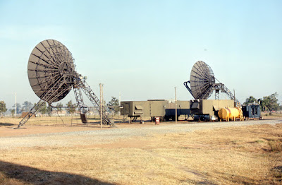
A few years later I was fighting 120hz hum on the baseband of an IWCS
microwave system feeding USAF command at the Korat Air Base in
Thailand. The hum was pretty high level and causing inter-modulation
problems on the 60 channels of signal sideband suppressed carrier
being applied to the microwave system.
We ended up with a couple of DCA DoD employees being flown in to help,
to their credit they were prior service and darn good at what they did.
After three days of testing all parts of the microwave system with a
very long distance and long duration phone call to the manufacture in
Calif, they still had not found the trouble.
I had stayed working with the DCA guys all of the time, during the
testing I noted the hum seem to lessen in strength with someone standing
directly behind the radio bay.
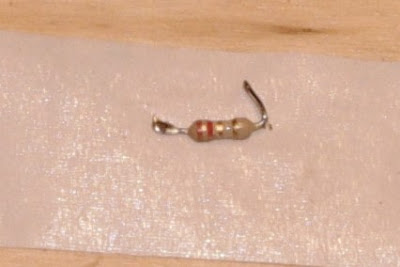
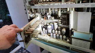
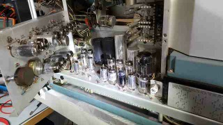
I went around to the back and took a close look, Yep! the mixer diodes
for the baseband order-wire were glass and exposed.
Put a length of black tape over them and the hum went away. Not the
power supply problem everyone was fixated on, it was diode photo
sensitivity. I guess we could have just turned off the florescent
lights too.
When I was 10 years old my father showed me how to use a Simpson
260 to check diodes and early transistors*. We were on the floor of the
living room with sunlight streaming in. I saw the forward resistance change
a lot when the glass diode was in sun light vs shade. It was this memory
that prompted me to try the black tape.
All the MW systems in SEA later received a MWO to change out the
order-wire board and I found that the assembly was a non-standard part
of the microwave system just for military use. Civilian deployment of
that microwave system had no need for the order-wire.
Thanks for the quick trip, for me anyway, down memory lane and the
memory of being an electronics tech hero for all of two minutes. The DCA
guys made me buy the first round at the club.

73 from an old friend….

Cliff Stoll — Still Passionate About Electronics (Video)

I open Chapter 3 of my book “SolderSmoke — Global Adventures in Wireless Electronics” with some quotes from Cliff Stoll: “Where’s the joy of mechanics and electricity, the creation of real things? Who are the tinkerers with a lust for electronics?” Well Cliff, that would be us!

I’m glad to see in the (obviously) recent video that OM Still has not lost his passion for electronics. You guys will like this one. Keep ’em comin’ Cliff!

SolderSmoke Podcast #200! 17, Knack Nobel, QCX, 630, UHF, Fessenden, TROUBLESHOOTING

DL3AO 1950

SolderSmoke Podcast #200 — TWO HUNDRED!!!!– Is available

http://soldersmoke.com/soldersmoke200.mp3

— Old friends on 17 meters.

— Another Knack Nobel in Physics.

— Hans Summers’ QCX transceiver: $50 IS THE NEW 10 GRAND!

— New Bands! 630 and 2200 Meters. BIG ANTENNAS!

— Nuke Powered QRP. No joke!

— The Challenge of UHF. Not for the faint of heart.

— Reginald Fessenden, Father of Phone.

PETE’S BENCH REPORT: The New Simple-ceiver. Soon to be a Transceiver.

BILL’s BENCH REPORT: Discrete, Direct Conversion, Ceramic Receiver in iPhone Box.

THE EDUCATIONAL PORTION OF TODAY’s PROGRAM:
HOW TO TROUBLESHOOT A HOMEBREW RECEIVER.

MAILBAG.

DL3AO 1950


Intuitive Repair of a Sony Shortwave Portable

A few years ago my wife got me this nice little Sony ICF-SW7600GR receiver. On the front it proclaims that it is “AM DUAL CONVERSION” and “PLL SYNTHESIZED.” It has a BFO, and a filter of suitable width for SSB. It also has a synchronous detector — it generates an internal carrier that matches the frequency and phase of the carrier being transmitted by the SW broadcast (or ham AM) transmitter. This helps overcome the selective fading that often plagues AM signals. Sony advises switching to USB or LSB once the synchronous generator locks onto the carrier. Pretty cool.

The BFO is the reason I wanted this receiver. And wouldn’t you know, when I dropped it, it landed EXACTLY on the little BFO fine tune control pot. It was as if the Radio Gods disliked all the fancy digi PLL synchronous IC circuitry.

I tried without success to find the value of the destroyed pot. Finally, last week I just decided to have a look in there to see if I could just figure it out.

On the board I could see that the pot only connected at two places, so I figured it would be a varactor circuit on the BFO with one end of the pot to DC and the wiper to the varactor diode. I figured I’d try a 10K pot.

This seems to have been some good radio intuition. It works. I went with a small trimmer because it is less obtrusive and because once I set the BFO in the right spot, I think the de facto channelization of the 40 meter ham band will keep most of the SSB sigs in tune. And the Sony only tunes in 1 kHz increments. If necessary I can move the BFO a bit with a small screwdriver. I just glued the trimmer pot onto the back of the receiver — two wires covered by heat shrink run back into the circuitry.

10k might be a bit too small. Maybe 100k would be better? As it is, I can move the BFO above and below the “zero beat” point, and I don’t need more range. Mouser has a small trimmer pot with a tuning wheel that looks like it might fit, so I may try for a proper repair.

FDIM: W8SX Interviews Mike Bryce WB8VGE

Mike Bryce’s many contributions to the radio art and QRP definitely puts him in the Homebrew Hero category. I have Mike’s “Hotwater Handbook” (about the legendary HW-8) on my bookshelf. Our intrepid SolderSmoke media team (Bob W8SX) spoke to Mike at FDIM 17. His comments on the joy of a good troubleshoot, and on the pernicious, unfixable nature of many recently marketed appliance radios really resonated with me.

Mike has special expertise on Heathkit gear: https://www.theheathkitshop.com/index.html

Listen to the interview with Mike here:

KEEP THAT GREEN FLAME BURNING MIKE!

Color Code Violation — Almost as Bad as Breaking Ohm’s Law!

A cautionary tale: How would you read the color code on that little resistor? It was plucked from a strip marked 2.2 ohms. And indeed it is red-red-gold. 2.2 ohms, right? But no, my friends. On the DVM it reads 2.2 kilo ohms. 2200 ohms. Believe me, that makes a big difference when it is in the Vcc line of your driver! It took me a while to find out WHY that driver wasn’t driving very well.

This turned out to be one of those very satisfying trouble-shoots — the problem was elusive and it wasn’t all my fault. But I should have MEASURED the resistor value before soldering it in.

Here is the scary part: The next resistor from the same strip was marked the same way, but measured 2.2 ohms. Be careful out there.

When Bypass Caps are Not Enough: Active Decoupling

I was having a noise problem with my NE602 Si5351 OLED display receiver. There was an annoying high pitched whine in the audio output. The source was easy to identify: If I reached in and unplugged the OLED display, the noise disappeared.

Next I had to find out how the OLED noise was getting into the rest of the receiver. It could have been through the SCL SDA or even the ground lines. It could have been just through capacitive or inductive coupling from the display board itself. A big clue came when I tried powering the display from a completely separate power supply: BINGO! The noise disappeared. So I knew the noise was going into the rest of the receiver through the Vc line that powered the OLED.

I had been powering the OLED from the 5V regulator on the Arduino Uno. In an effort to isolate the noise, I put a separate 5V regulator in the circuit for the OLED. No joy — noise still there. I then tried putting an RC low pass filter between the OLED and the 5V regulator. Still had the noise. Finally I remembered something from the AF AMP circuits of Roy Lewallen, Rick Campbell and Roger Hayward. ( I think Roy was the pioneer on this one.) They all used an “active decoupler” between the first AF amp and the power supply line. I confirmed that it was my first AF amp that was picking up the OLED noise. I built the active decoupler (just three parts!) and the noise disappeared. GONE!

There are only three parts, but the way this circuit works is kind of complicated and not very intuitive. There is a good discussion of how it works here:

www.facstaff.bucknell.edu/dkelley/elec351/Lab/elec351lab5_sp04.doc

Roy, Rick and Roger were using this circuit to knock down 60 Hz AC hum, but I found that my OLED noise was at around 200 Hz — I figured (correctly) that the active decoupler would take care of this as well. I think this little circuit can be useful in dealing with the kind of noise generated by the digi displays that many of us are now using.

David Rowe has a really interesting analysis of this circuit here:
http://www.rowetel.com/?p=4781

KD4PBJ’s FB BITX 40

Hi Guys!

I have to admit something. It’s a learning experience.
A year or two ago I bought the Bitx boards from Sunil in India and while they are on the To Do list, haven’t been built up yet. I have close to 20 projects on my to do list, so when Farhan’s prebuilt SMT version became available I decided to get one.
I had gone over to TenTec before they shut down and bought a few of their two piece enclosures since I like how attractive they are and also inexpensive.
The Bitx went into the enclosure quickly and I measured a little over 10 W out with my scope. I fed a -125 dBm signal in using my HP8640 generator and could easily hear the tone.
So a really sensitive receiver. Nice and quiet too!
I got a SMT digital dial from QRP Guys and got it in the case. Now I heard a high pitched whine in the background. Nuts!
So I posted to the Bitx yahoo group asking for help in reducing the noise. I built a R/L/C filter network, added ferrites, built a copper clad and brass enclosure for the display. Nada. Noise still there. Adding adhesive copper tape didn’t help either.
This was driving me mad. For some reason, and I don’t know why, one evening I decided to try a gel cell. Success!!! No noise whatsoever.
Here’s what happened….
When I first built the radio in early December I tested it on my operating bench. On that bench is a older Power Designs 0-60V 0-5A linear bench supply.
After adding the display I did integration on my soldering lab bench and for that I grabbed my HP E3610 supply which it turns out is heavy but switching, not linear. The noise was coming from the supply!!
If I hadn’t tried the gel cell it may have taken me a long time to figure this out.
Saturday of last week was my first contact with it. I worked two Canadian stations with it, and both came back to me the first time after I answered their CQ’s. I did have one issue and that’s the well documented drift. During the QSO I watched the display drift upwards as I held the PTT button down. I replaced the 100 pF and 47 pF chip caps in the VFO with disc ceramic parts from Mouser and now it doesn’t drift.
While doing the work in the VFO section I also tweaked the trimmer cap a bit to bring the bottom range up to the start of the phone band, as before the bottom end was below 7 MHz and I figured that didn’t do me much good for a SSB rig to waste a lot of its tuning range on the CW segment.
Here are a few pictures. Mic is home brew too, having made it for my MMR-40 rig.

Hope all is going well for you and looking forward to the next Solder Smoke.

Chris KD4PBJ


Of Waterfalls, SDRs, and Homebrew Analog Rigs: Words of Wisdom from W8JI

W8JI


It happened again today. Conditions were good and I was BOOMING into the NYC area on 40 meters. 40 over. Everyone liked the signal and said it sounded great. Except for one anonymous grump who chimed in to say that I was “9 kc wide.” I imagine he was basing this on a quick look at his super-dooper SDR waterfall, without any consideration of signal strength or the characteristics of his own receiver. Sigh. The Waterfall Police had struck again.

OM W8JI gives a great description of the pitfalls of this kind of “you’re-too-wide-because-my waterfall-says-so” reasoning. Check it out. And keep it handy in preparation for your next encounter with the 40 meter Waterfall Police.

https://www.w8ji.com/checking_bandwidth_with_receiver.htm

‘Tis the season… To Worry about Electrostatic Discharge

Read and heed, or you’ll be sorry. The cold weather causes us to spend more time in the shack and to work on new homebrew project. Some of these projects may involve sensitive, delicate, solid-state components that can be instantly wiped out by that little winter spark from your finger…

Take a look:

http://soldersmoke.blogspot.com/2016/01/an-electro-static-bandaid-to-protect.html

I have to be especially careful this year, because Northern Virginia is now officially in a drought. So that spark-friendly dry winter air is likely to be even dryer this year.

Oz Tektronix ‘Scope Repair (in Juliano Blue)


Rob is a braver ham than I. When my Tek 465 quit, I tried to fix it, but quickly chickened out.
Very nice that he painted his in Juliano Blue.

Dear Bill and Pete,


I do enjoy your podcast, and I must present an offering to the “Gods of Homebrew”,
An on-line find of an old Tek 545 oscilloscope presented a chance to enjoy the warmth of 100+ tubes (once repaired)
The outside was heavily scratched, the inside looked like a chicken coup, but no major bits missing or broken.
Lots of cleaning, testing all tubes,(using the excellent uTracer tube tracer), replacing the broken 3, remounting the cooling fan, lots of reading about tube oscilloscopes, adjusting the trigger circuit, rebuilding 3 electrolytic power supply capacitors, sandblasting the cabinet and a coat of BLUE paint.
Voila, the joy of (visual) oscillation! (1MHz 2V p-p)

Rob VK5RC