SolderSmoke Podcast #228

Soldersmoke Podcast #228 is available:

Of course, no travel. But vaccines are here so maybe soon we can leave our shacks.

In the meantime:

I’ve been playing chess against AI bots on chess.com.

Netflix recommendation: The Bureau. From France. A review from NPR:

https://www.npr.org/2020/06/22/881642358/addictively-suspenseful-thriller-series-the-bureau-will-keep-you-on-edge

A reading from “Conquering the Electron.” Germanium vs. Silicon.

Bill’s Bench:

The KLH Model Twenty-one II. Acoustical Suspension. First receiver WITH A PILLOW! Bad speaker? Blown AF amp finals. Hot heat sink. VBE Multiplier. Desitin.

Tony Fishpool’s recommended LM386 boards. 10 for 11 bucks. Nice. They work. Pictured in the Amazon ad at the upper right of the SolderSmoke blog page.

Putting a digital display on the Lafayette HA-600A

Test gear trouble. My Radio Shack multimeter getting flaky. I many need something better. Auto ranging? My beloved Maplin AF generator died – will have to fix. I need that thing. Probably a bad chip. Good thing they are socketed.

I almost forgot about SKN! But I remembered and I made one contact with the HT-37 and Drake 2-B.

Pete’s Bench:

Presentation to RSGB on Homebrew.

TenTek Troubleshoot.

Swan 240? Looking nice.

SDR adventures.

MAILBAG

Bill N8ET sent me some really nice Showa 9 MHz 8 pole crystal filters.

Kevin AA7YQ Smoke jumper! Building a hybrid SDR.HDR rig. Launched blog. FB

Nick M0NTV working on similar HDR/SDR project. Great video.

Grayson KJ7UM Hollow State Design – Launched a new blog. Very FB!

Thomas K4SWL of SWL Post blog. Kearsarge Mountain Transmission system. And recent events.

Peter VK2EMU Poetry. CW poetry.

Pete WB9FLW looking at DSB rigs…

Drew N7DA Feels not like a real ham because he hasn’t built a quad from bamboo. Which type of landscape bamboo is best for antennas?

Ryan Flowers of MiscDotGeek.Com blog is also watching the Tally Ho YouTube videos of Leo Sampson. Wants to put a WSPR beacon on the Tally Ho.

Joe KF5OWY Working with diode ring mixers, trying to see the mixer action on his ‘scope. 1 and -1!

Jim AB9CN sent a cool idea about how to do a 20/17 Moxon.

Roy GM4VKI – I thanked him for his article in SPRAT about putting a 2n3904 on the output of an NE602 10P mod. Brilliant.

Roger Hayward Told him that I really liked his Dad’s recent web site updates.

Farhan – Jokingly cursed me for showing him the Oscillodyne regen of Hugo Gernsback and Jean Shepherd. “Now I will have to build this!”

Too Simple? Deficiency of the Lafayette HA-600A Product Detector?

I’ve been having a lot of fun with the Lafayette HA-600A receiver that I picked up earlier this month. Adding to the mirth, I noticed that on SSB, the signals sound a bit scratchy, a bit distorted, not-quite-right. (I’m not being facetious; this is an interesting problem and it might give me a chance to actually improve a piece of gear that I — as a teenager — had been afraid to work on.)

Before digging into the circuitry, I engaged in some front panel troubleshooting: I switched to AM and tuned in a strong local AM broadcast signal. It sounded great — it had no sign of the distortion I was hearing on SSB. This was an important hint — the only difference between the circuitry used on AM and the circuitry used on SSB is the detector and the BFO. In the AM mode a simple diode detector is used. In SSB a product detector and BFO is used. The BFO sounded fine and looked good on the scope. This caused me to focus on the product detector as the culprit.

Check out the schematic above. Tr-5 is the product detector. It is really, really simple. (See Einstein quote below.) It is a single-transistor mixer with BFO energy going into the base and IF energy going into the emitter. Output is taken from the collector and sent to the audio amplifiers. (A complete schematic for the receiver can be seen here: https://nvhrbiblio.nl/schema/Lafayette_HA600A.pdf )

I had never before seen a product detector like this. One such detector is described in Experimental Methods for RF Design (page 5.3) but the authors devoted just one paragraph to the circuity, noting that, “We have not performed careful measurement on this mixer.” The lack of enthusiasm is palpable, and probably justified.

A Google search shows there is not a lot of literature on single BJT product detectors. There is a good 1968 article in Ham Radio Magazine: http://marc.retronik.fr/AmateurRadio/SSB/Single-Sideband_Detectors_%5BHAM-Radio_1968_8p%5D.pdf It describes a somewhat different circuit used in the Gonset Sidewinder. The author notes that this circuit has “not been popular.”

To test my suspicion that the product detector is the problem, I set up a little experiment. I loosely coupled the output of a signal generator to the IF circuitry of the HA-600A. I put the sign gen exactly on the frequency of the BFO. Then, I switched the receiver to AM, turning off the BFO and putting the AM diode detector to work. I was able to tune in the SSB signals without the kind of distortion I had heard when using the product detector.

So what do you folks think? Is the product detector the culprit? Or could the problem be in the AGC? Should I start plotting a change in the detector circuitry? Might a diode ring work better?


Chip Replaced, GSC 6000 Counter Fixed

This thing has been half-broken for a long time. I needed to get the input for 40 MHz – 650 MHz working I got the a replacement SP8630B Plessey divide-by-ten counter chip on e-bay, and yesterday I extracted the old chip and put in the replacement. I took great care NOT to solder this one in upside down (as I had done with another chip replacement in this counter). I used solder flux and solder wick to gradually get the pins free of the board. (You can see the old chip in the picture above.)

As to what happened to the original SP8630B chip, John over on the Vintage Test Gear Facebook page wrote:

The Plessey SP8630A/B is an ECL divide by 10 prescaler, with a upper working frequency of 600MHz. That generation went out of production in the late 1980s. Plessey was bought by a Canadian company now called Micrel. You may be able to find one from one of the specialist obsolete component companies, but it may be dead on arrival. Those ECL ICs had a fairly high mortality rate if they are very old.

It is the old story of “metal migration”. In early semiconductors very small impurities in the silicon structure cause minute bits of the metallisation to leach out into the essentially non-conducting silicon insulation. Many old devices, although they have never been used, were found to be very leaky and this degrades the gain of the active devices. The worst types are the very old Germanium transistors.

As the semiconductor scientist learnt more about the super cleanliness required and the better purification of the metals the problem tended to improve. The Marconi company I worked for back in the 1980s had a real problem with comms satellites failing after a few years of service. Of course you can’t go up there and swap out the faulty devices. Accelerated ageing of a backup satellite showed that some devices just stopped working after being subjected to high and low temperature cycling, which is a common problem with satellites in orbit!

I am liking this little machine more and more. It is very simple — no microcontroller, just a collection of gates. I discovered that the main main crystal oscillator is actually built inside a little oven to keep the temperature stable — oscillator and the oven stay on as long as the counter is plugged in, even when the device is switched off. I calibrated the counter with WWV and with my HP8640B and with my little Feeltech sig gen counter. I wish I knew how to calibrate the counter in the Rigol DS1102E oscilloscope.

The Bitsy — Homebrew Double Sideband from Scotland

This is such a beautiful project: it involves DSB, homebrew, troubleshooting, George Dobbs, SSDRA, J310s, a box kite, and ham radio nostalgia. I was struck by how similar the Bitsy looks to some of my own DSB creations (but the Bitsy is nicer). I’m really pleased to find a DSB project coming out of the UK — when I was there, DSB was kind of frowned upon by spectrum preservation zealots. I say there is plenty of room for the very few homebrew DSB rigs that will ever grace the airwaves with their presence. Thanks John. Have fun with all your projects. 73 Bill

Hi Bill

In the early 80’s I built and experimented with Direct Conversion Receivers and had a lot of fun with them. I came across a 40M DC cw transceiver by the late Rev. George Dobbs in a Practical Wireless magazine and decided to build it. Whether I was just lucky I’m not sure but it worked first time and I had several cw contacts with it. It was called “The PW Severn”. I then discovered DSB and looked into modifying the wee rig. I gave George a phone, no internet in those days, and explained what I was proposing to do and if there was any advice he could offer. His reply was , “it should work so try it and see, any problems get back to me”. It worked and I had a lot of fun with it. I used to take it portable and with a box kite to support a long wire and worked all over Europe.

It was after reading and learning about circuits and home brewing I wondered if I could design and build a DSB transceiver of my own. I had plenty of articles and most importantly a copy of Solid State Design, now well thumbed.

So the “Bitsy” was born. It is an 80M DSB transceiver. The PA produces about 2 watts. I took what I thought was the best for each module and built it using six circuit boards which I designed and etched myself. Nowadays I use the Manhattan method for one of circuits. It is much easier and quicker.

Like most home brew projects, the fun is in the building and the wee rig lived in a box for several years. Probably over 30. My doesn’t time fly. I came across it again while looking through my boxes and decided to give it an airing. Expecting it to work on power up I was quite shocked when it produced nothing on both receive and transmit. After staring at it for a couple of minutes I unscrewed the lid and studied the wiring for a dry joint. Nothing so I switched on my Digital Multimeter and Oscilloscope. I soon found out that the output from the VFO was missing. The VFO uses one FET and two PNP Transistors for the buffers. The scope soon proved that the FET was faulty. I used an MPF102. These are hard to get so I replaced it with a J310. While I had the VFO out I also replaced the 9.1v zener diode, which provides a regulated voltage for the FET, with a 78L05 connecting the centre pin via a 580ohm resistor to earth. This gives me a 9.3v regulated supply for the oscillator. It is now back in full working condition.

With the Covid 19 epidemic I, like a lot of the Amateur Radio fraternity, am spending a lot of time in the shack and looking for new projects. I am buying back my old FT200 which was my first rig. An old friend and lapsed amateur has still got it and agreed to sell it back to me. It is still in a good condition for being nearly 50 years old and just needs some TLC. When it is finished it will take pride of place beside my restored Heathkit SB104A. And they say nostalgia is not what it used to be!!

John Forsyth

GM4OOU


HP8640B Internal Frequency Counter Fixed (More Repairs Pending)

The HP8640B is a complicated machine. Above you see just one sub-assembly, and the page from the manual that describes it. This is what I’ve been working on. The little spring “tine” fell out of one of those discs behind the two control knobs. So I had to open this thing up, find the spot from which the tine had fallen, and glue it back in.

I used Gorilla Super Glue, followed 24 hours later by a dab of JB Weld “minute weld” dual epoxy. One of the other tines was about to fall out, so I went ahead and gave all the tines in this assembly the glue treatment. ( I bought some “Weld On” acrylic cement but the warnings on the label were quite sobering. So I left that can sealed up.)

This morning I put the thing back together. This is not easy. At one point a spring popped and a tiny metal part that is probably irreplaceable seemed to fly away into the black hole that is the shack’s carpet. I had just about given up hope when I found the thing sitting right in front of me on the bench. TRGHS.

The HP8640B fired up right away without trouble and the internal frequency counter is working fine.

As I noted in the last SolderSmoke podcast, a very nice community devoted to the HP8640B has developed around the world. Here are some of the notable participants:

Bill at Electronics Revisited is a very nice fellow with lots of experience on the HP8640B. He offered to sell me a replacement unit for the assembly pictured above. If you have an ailing HP8640B and are looking for someone to work on it for you, Bill is the guy you should talk to: http://www.electronicsrevisited.com/ He also very kindly offers to answer any questions you may have about the HP8640B.
Here is the e-bay page of the fellow in Bangalore who makes the brass gears. Mine are on the way!
Marcus VE7CA has a great site devoted to the HP8640B: https://www.ve7ca.net/TstH86.htm
BH1RBG in China has a nice site describing his adventures with the HP8640B: https://sites.google.com/site/linuxdigitallab/home/hp8640b-20v-power-supply-down
K6JCA has a good blog post about fixing the tines and the gears:
Steve Silverman (who gave me this HP8640B) found a really useful history of the device:
And of course special thanks to Dave VE3EAC who alerted me to the falling tine problem and put me on the path to a successful repair.
The gears should be here in a few weeks, so that will be another opportunity to work on this HP8640B. Also there are some tines in the attenuator assemby that might reinforce with the glue treatment.

HP8640B — Fault Found! A very TINY and Hard-to-Fix Fault

I’ve been troubleshooting the internal counter in my HP8640B signal generator. The generator itself works fine. And the counter works fine for all signals coming in on its “external” port. But the internal counter stopped working properly above 16 MHz. So I started digging into the manuals and the schematics, re-familiarizing myself with the digital logic behind pre-microcontroller frequency counters. NOTE: If you are working on one of these, be sure to be using the correct version of the manual and schematic. At one point I found a really nice high def copy of an HP8640B manual (for one used in a Patriot Missile System!) only to discover that MY A8A3 board was significantly different from the one in this manual. BAMA provided a manual that matched my device: http://bama.edebris.com/manuals/hp/8640b/

Every dark cloud has a silver lining. Here, the silver for me came from opening up the HP8640B. What an impressive looking piece of gear. It looks like something from the Apollo command module, or perhaps from a nuclear weapon. “The RF source is a 256 to 512 MHz cavity-tuned oscillator that is mechanically tuned…” There is phase lock circuitry. The are AM and FM modulators and a really useful array of attenuators. There is a frequency counter with an external port and an internal frequency counter that measures the original 256-512 MHz signal, then divides down to give a very accurate readout of the output frequency. This is the kind of device that would generate a cult following. Count me in!

Also, I’ve sometimes lamented the lack of VHF test gear on my work bench — the HP8640B could really help me move me into the VHF range.

I started the troubleshooting with some observations and noodling. At what frequency did the internal counter stop working? What did the readout look like when it stopped working? What device failure could lead to these symptoms? I was aided in this by suggestions sent in by readers of my previous blog posts. Thanks guys.

I was just getting ready to start some intrusive testing on the logic devices in the internal counter when Dave VE3EAC sent me this:

—————–
I think you might be overthinking the failure mode here. I had a similar problem with my unit and it was one of my early Covid-fix-it projects. There is an assembly that controls the bands on the front. It has the famous gears that crack. On the back side are two sets of rotary switches that control a lot of stuff. The switches are of a very unique HP design and offer a lot of advantages over traditional switches EXCEPT they fail in an unusual manner. A PC board has all of the interesting wiring and very tiny double leaf springs short tracks together as needed. The springs tend to break away from the plastic posts on the rotating plate and not make the needed contact. Very carefully examine the insides of the 8640 and your bench top to see if any have fallen out. These are difficult to buy or fabricate. The disk is designed to be rotated 180 and use a new set of posts to locate the springs. Use a small dab of epoxy to set in place. The totally mechanical repair fixed my unit that also would not read above 16 MHz. There are a number of web pages that give great detail of this repair. Also it is worth while to replace the Delrin gears if they are cracked. Replacement brass ones are available on eBay and they will permanently fix the gear problem.
—————

I had thought about the problem being in the frequency range switch, but I had sort of tested for this by slowly rocking the switch through various positions as I watched the display. A dirty rotary switch will usually allow the circuit to intermittently work as you rock the switch. But this didn’t happen. And the HP switch felt quite sturdy, so I focused on the circuitry.

When I got VE3EAC’s message, I carefully flipped the HP8640B over and for the first time opened the bottom of the compartment. The bottom view is much more impressive than the top view:

The switches that VE3EAC wrote about are just below the ribbon cable near the center front. I could see the little springs that he was discussing on the switches. They appear MUCH more delicate than the rotator on a standard rotary switch. And I didn’t see any of them lying around below the switch. But when I tried to flip the HP8640B over, something in there moved and caught my eye. I pulled out some tweezers and pulled this out:


Wow. That little spring contact fell off the switch. That was preventing the HP8640B internal counter’s time base from changing as I went above 16 MHz. It is ironic that such a big and solidly built device such as the HP8640B should be laid low by such a TINY part.

This gets me back to my original question: Discretion or valor? Getting that spring back onto that switch will not be easy. VE3EAC sent me this K6JCA link describing how to do this. Yikes, it even requires the purchase of a special tool!
I’m going to let the HP8640B sit there with the cover off for a while. It will be taunting me, challenging me to fix it, to make it work the way Hewlett and Packard intended. It may take a while, but I think I’m going to have to accept this challenge. I’ve become real fan of the HP8640B and it would be a shame to leave it wounded like this.

The Agony of Troubleshooting — From China

I am troubleshooting my beloved NYC HP8640B Signal Generator (thanks to Steve Silverman and Dave Bamford). Some of you may wonder why I don’t just replace this beast with something small, lighter, cheaper and newer. Well, I have not found any new sig generators that will do what this beast does: It goes all the way up to 256 MHz (higher with an extension kit). It has a great attenuator in it so you can set the output just where you want it. AM or FM modulation. Really useful. So I think I’ll fix it.

My problem is that the internal freq counter stops working above 16 MHz. Using the very extensive documentation, and without even really opening up the machine, I think I have located the fault. I think it is in the Counter Time Base Assembly board A8A3. Now of course, the fun begins. (Tips, advice, solutions, and words of encouragement would all be appreciated.)

While planning my assault on A8A3, I came across the web site of BH1RBG. He too has recently been working on an HP8640B. His problem was different, but when I read through his site I saw evidence that the agony of troubleshooting is something that is the same all around the world. Check out his description of the agony:

I even suspected the LM723 should had something bootstrapping circuit, make sure the Q4 sure start. Because the external reference VR3 is floating too, oh, my godness.

I became hopeless, and ordered several LM732,and waiting delivery for days. This beast frustrate me so deeply, changed the LM723 does not help anything. And i almost desoldering everything in the board!

Oh man, I’ve been there. Several times while in the throes of a troubleshooting battle I have actually had dreams of removing all the parts from a troublesome PC board.

BH1RBG has a very interesting site with lots of ham radio projects:

https://sites.google.com/site/linuxdigitallab/rf-ham-radio?authuser=0


Taming Glitches in a Soyuz Space Clock (Plus — Inside a Logic Chip and How Crystals Work)

Thanks to Bob KD4EBM for sending this.

There is so much good info in this video: They crack open a logic chip and look at the internal construction (it is entirely understandable by mortal minds). They use cool test gear to troubleshoot the clock from a Soyuz spacecraft. They explain very clearly the series and parallel resonances of quartz crystals, then display these resonances on a very nice spectrum analyzer.

The creator of the video is CuriousMarc. He has many other interesting projects:

https://www.youtube.com/c/CuriousMarc/featured

https://www.curiousmarc.com/

His bio is here:
One paragraph from his bio really resonated with me:

Working on this old stuff forces me to deal with the very fundamentals of electronics (and electro-mechanics). The principles are exactly the same as today, but nothing is hidden in mysterious circuits – you can understand and fix everything. Years of Moore’s law has sure given us gobs of transistors, oceans of memory and a glut of gigacycles, but many times, particularly in consumer hardware, these are simply used to cover up poor and inefficient designs – and resource devouring software. What Intel giveth, Microsoft taketh away, as they say. It often irritates me that my PC takes several seconds to react to a simple command, in which time it must have executed billions of unnecessary instructions and consumed a few gigabytes of memory, no one knowing exactly what for anymore. Nothing like this in old high-end hardware: designs are pure and efficient, and the lack of resources is compensated by engineering mastery and immense cleverness, which is a joy to reverse engineer. Not only does it teach us timeless electrical fundamentals and engineering tricks, but it also gives us a much better appreciation of today’s tech. How did all the technology we take for granted came to be? It will make you a far better engineer and inventor if you take the time to be a thorough student of the inventions of your illustrious predecessors.

Great Video on PC Board Techniques, with a Focus on Surface Mount

Wow, lots of wisdom in this video from Leo Fernekes. Great hints and kinks on prototyping with copper clad boards. I need a Dremel just so that I can make Leo’s board cutter. And I can see that I need some of that liquid flux and isopropyl alcohol. Surf boards and headers! Who knew? Teflon coating for the wires — gotta get it. Glad to see that Leo is also a fan of copper tape.

His emphasis on the importance of stage-by-stage construction and testing is right on the mark.

My only disagreement with Leo is about his use of steel wool. I’ve found that steel wool will inevitably cause little tiny “Murphy Whiskers” to float around your workbench. They will eventually settle onto the most inconvenient and damaging place on your board. So I have banished steel wool from my workshop. Those green, non-metallic Scotch Brite pads work just as well and don’t cause shorts.

Three cheers for Leo. He is based in Thailand. He has an interesting background and some really amazing projects and insights:

http://www.luminati.aero/leofernekes

http://www.fernekes.com/blog/

https://www.youtube.com/channel/UCe1bjEcBichpiAMhExh0NiQ/videos

Thanks to Tore LB4RG for alerting us to Leo’s video.

Mike WU2D’s Great Drake TR-3 Refurb Video — Part 2

Mike WU2D made another very nice video about his Drake TR-3 refurb.

He cracked me up when he noticed that one of the calibration oscillators was 30 Hz off. “Let’s pretend we care,” said Mike. Indeed. But it was probably wise to tackle this problem, given how upset modern hams seem to get with 30 Hz discrepancies. Mike noted that the problem was casued by “aging cystals.” Yikes! Another thing to worry about, along with the Southern Magnetic Anomaly.

Once again Mike has added a useful term to our lexicon: “The Dribble Method” of signal injection (or extraction): Just wrap a few turns of insulated wire around the tube or IF can and inject or measure away.

Neutralization! Now there’s a blast from the Thermatron past. I haven’t done that in a long time. I liked Mike’s “reverse neutralization” method.

Mike’s video featured some real Boatanchor eye candy. That Heathkit HR-10 receiver caught my eye, as did that HP signal generator.

Thanks Mike. One hand behind your back OM.

WU2D’s TR-3 — Mike Refurbishes a Nice Old Drake Transceiver (PART 1) (Video)

There is a lot of Tribal Knowledge in this video. And good discussion of the many moral issues faced by those of us who work on old gear.

— Mike seems apologetic about his blatant and blasphemous spray painting of the Drake copper chassis. As well he should be.

— His stubborn replacement of the tube socket (to allow for shielding) seems wildly reckless to me. The Radio Gods may retaliate with some unexpected instability in that circuit.

— He CORRECTLY refers to the rewiring of the final circuity (to accomodate 6146s) as “the evil thing.” Indeed.

— I love in the beginning how he is listening to some ham radio chatter and the guy is talking about the selection of COM PORTS. With old radios “we don’t have COM PORTS — we have an antenna connector.” Well put Mike.

— I was struck by how much the TR-3 innards look like my 2-B receiver. But the TR-3 has no dial strings. That is a major technological improvement. And it has a PTO. Was this a case of Collins envy?

— Mike adds a useful word to the lexicon: “shotgunning” — the indiscriminate replacement of entire categories of parts in old radios. Now I don’t mind shotgunning the electrolytics (some people bitterly oppose this). But I agree with Mike on the wisdom of keeping the paper caps in there.

I am looking forward to Part II. These videos are like “This Old House” but instead “This Old Rig.” And I will go back and look at Mike’s video on the Power Supply refurb. Thanks Mike.

Fixing up a Radio Shack DX-390 (AKA Sangean ATS-818) While Suffering from Fat Finger Syndrome


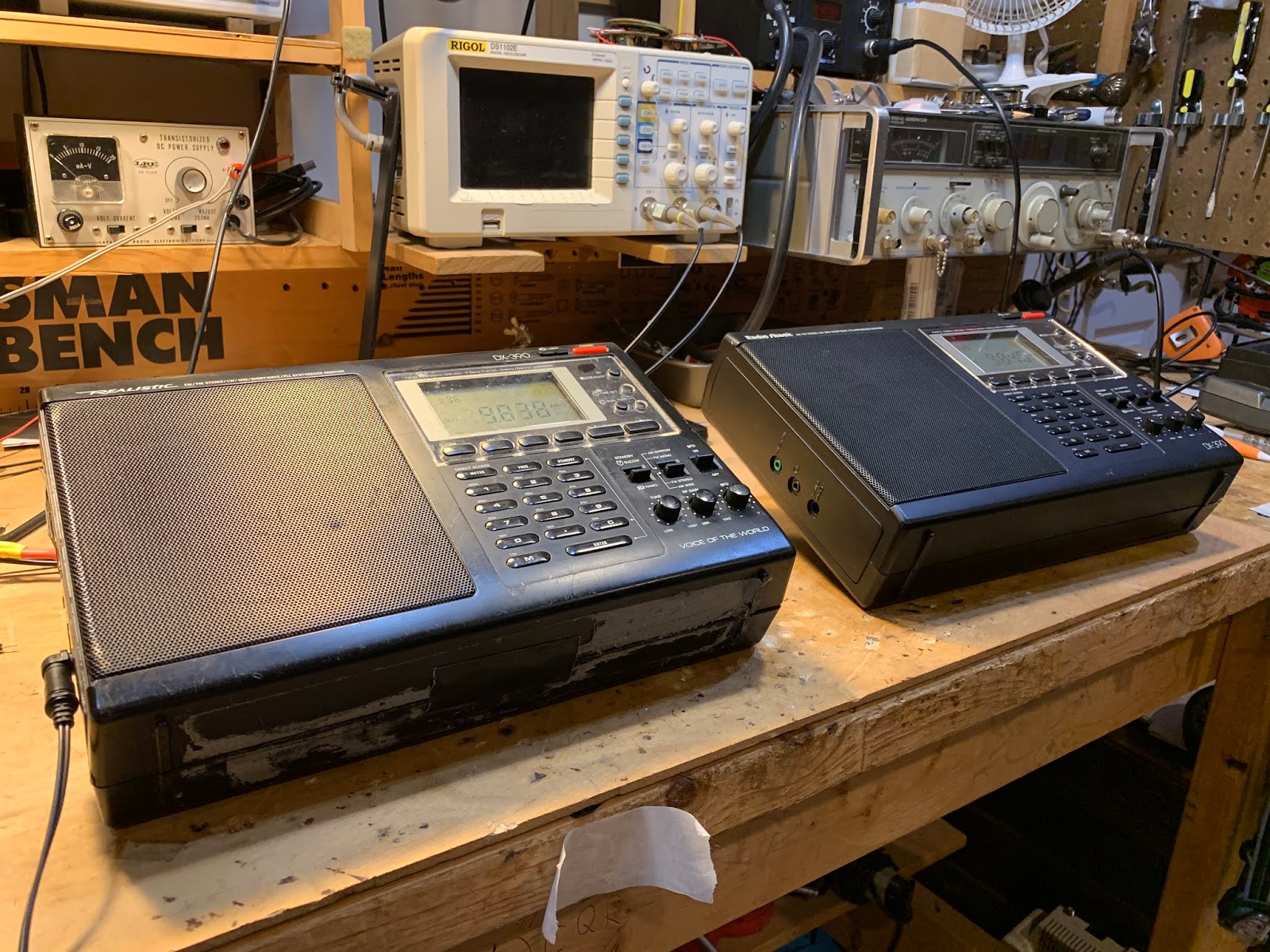
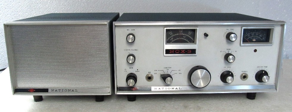
I’ve had this Radio Shack DX-390 portable receiver since the early 1990s. I bought it when I was in the Dominican Republic. It accompanied me on some interesting trips to the Haitian border, and on one very memorable 1994 trip to the Haitian capital. I have made some CW contacts with it serving at the inhaler.

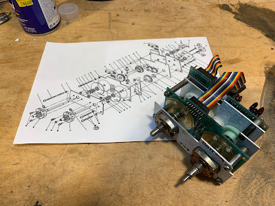
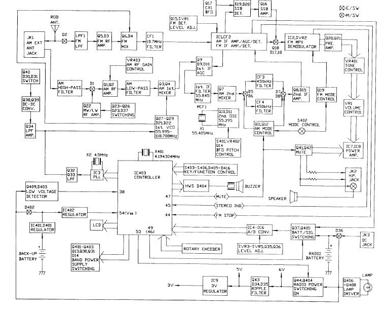
Click on the diagram for a better view. It is a dual conversion superhet. First IF is at 55.845 MHz. There is a big 90’s era IC-based PLL oscillator that runs from 55.995 to 118.7 MHz — The main tuning dial moves this oscillator. Second IF is at 450 kHz. There is an oscillator at 55.395 that takes the signal down to 450 kHz. Selectivity (not a lot) is provided by ceramic filters. Finally there is a product detector and a 450 kHz oscillator that produces the audio. While there are many mystery chips in this receiver, there is also a lot of discrete-component analog circuitry in there — it is kind of a pleasing mix.

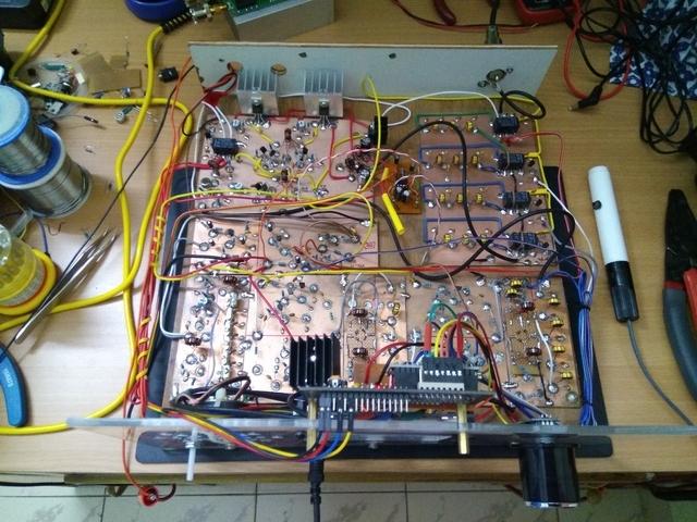
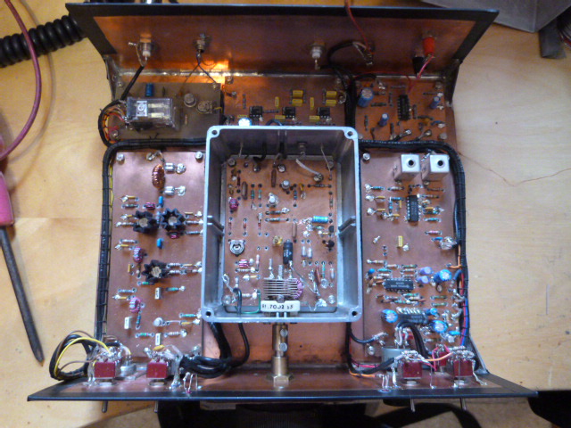
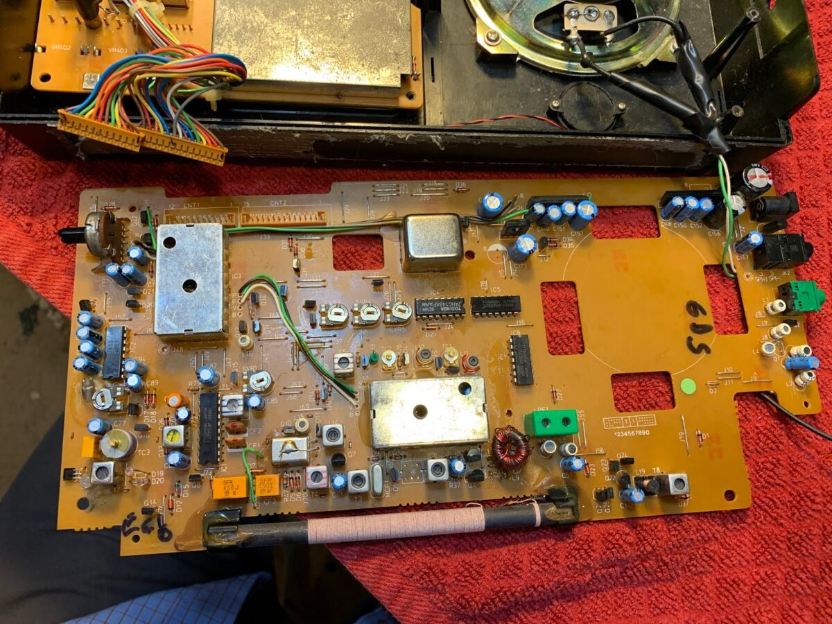
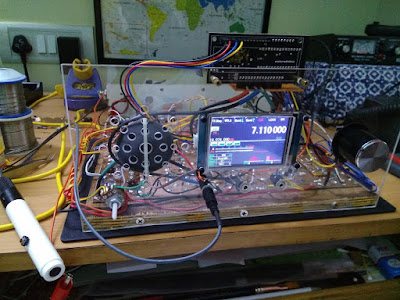
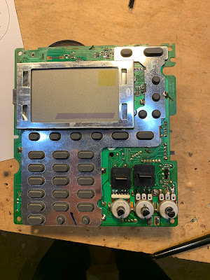
DX-390 Main Board. Note kludged toroidal replacment for L10 (just above ferrite antenna)

The old DX-390 suffered a lot of wear and tear. The case is very beat up. The most serious problem was that at some point, probably on a cold, dry, winter day in Virginia, static electricity took out the FET in the receiver’s front end. I made a half-hearted effort to fix it, but it never really worked properly.

I occasionally found myself thinking of this receiver. I spotted one on e-bay not long ago, and bought it. This newer one was in very nice shape.

But that old one was kind of staring at me from the corner of the shack. “C’mon radio man,” it seemed to say, “can’t you fix a shortwave receiver?” So this week I took up the challenge.

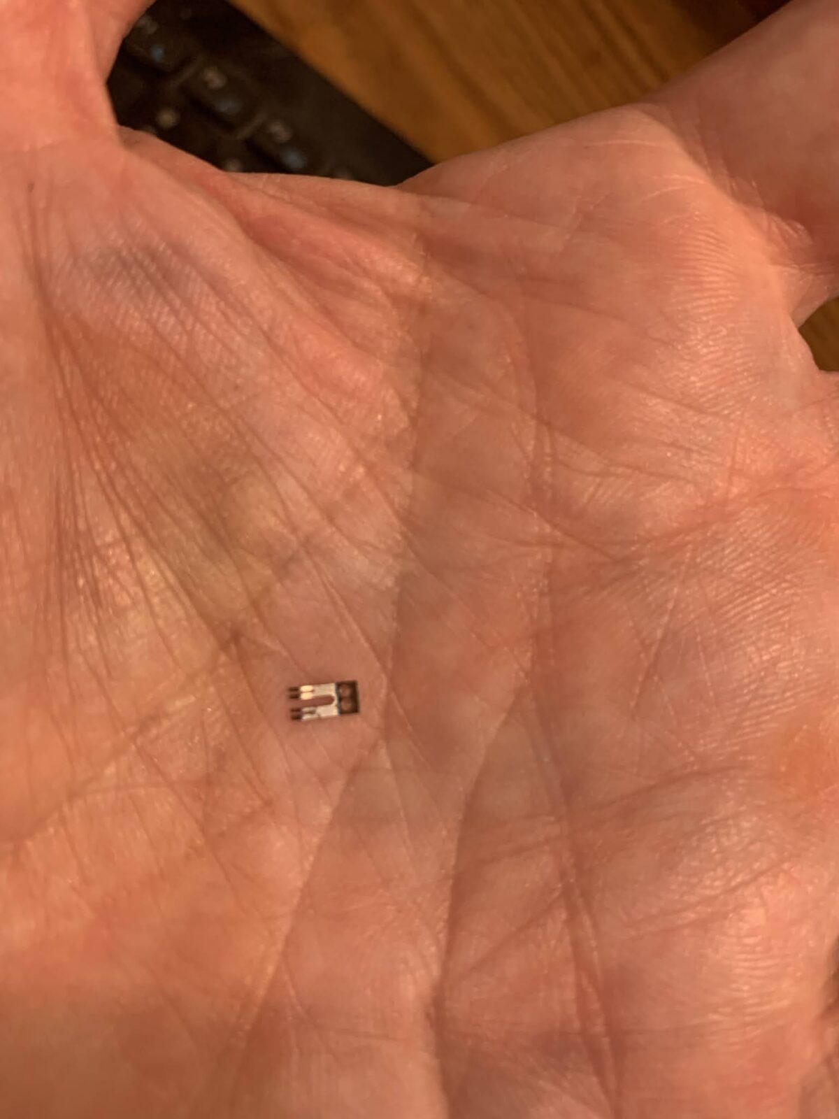
First the FET. I had kludged an MPF102 in there, but that didn’t seem to work well. Internet fora seemed to think that a J310 would do better, so I installed one of them — it did seem to work better. (Note: Pete Juliano likes J310s — TRGHS.)

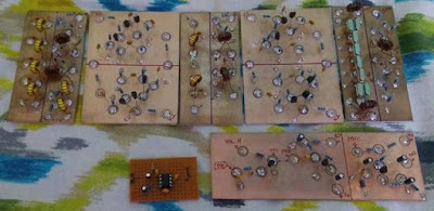
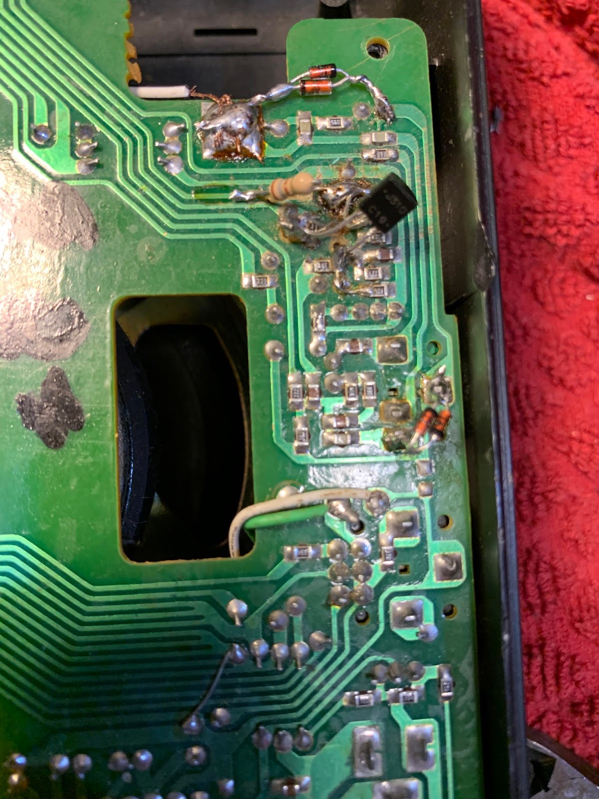
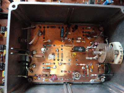
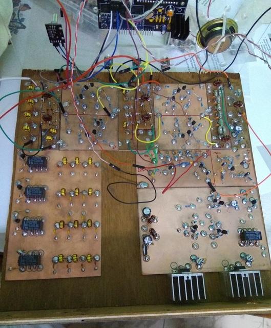
Kludged in J310. And two sets of back to back diodes

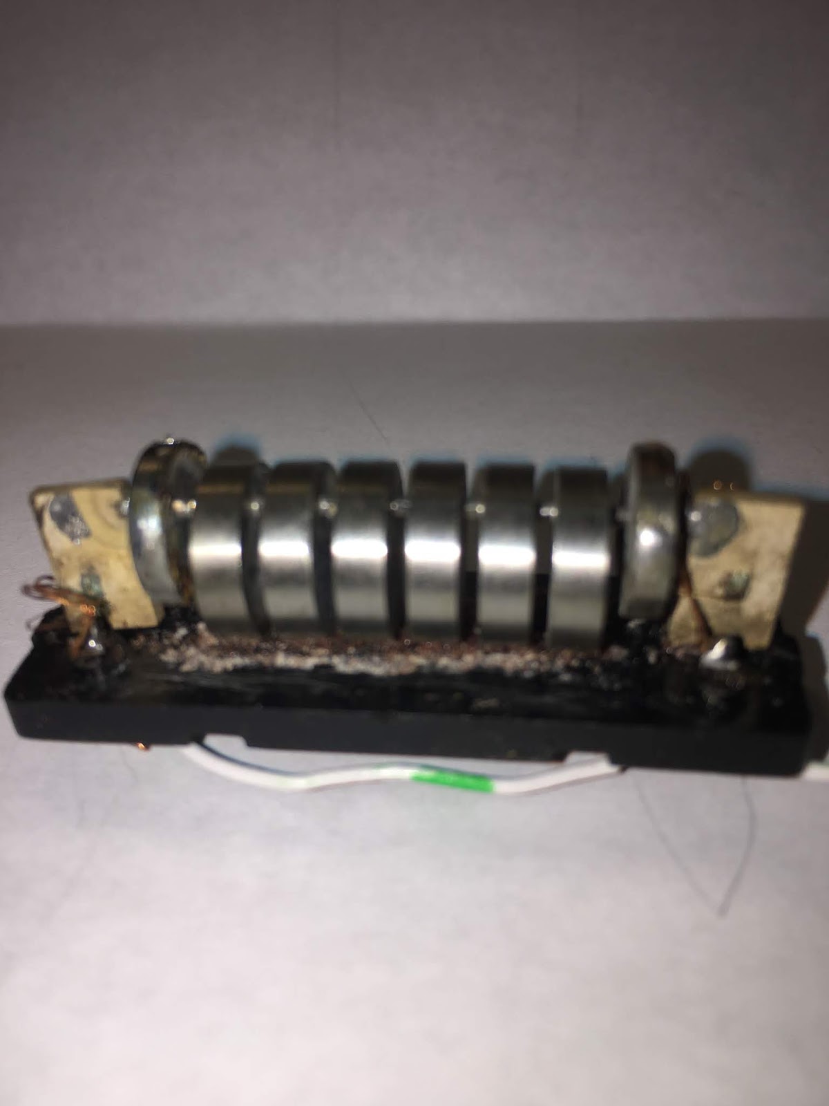
During my earlier repair effort I had apparently destroyed the front end output transformer (L10) but I discovered that I had replaced this with a toroidal transformer. It still worked, so I left well-enough alone.

I was pleased that the old receiver was receiving OK, but there was a problem: The “BFO” control wasn’t working. The BFO would come on, but turning the BFO control did not vary its frequency.

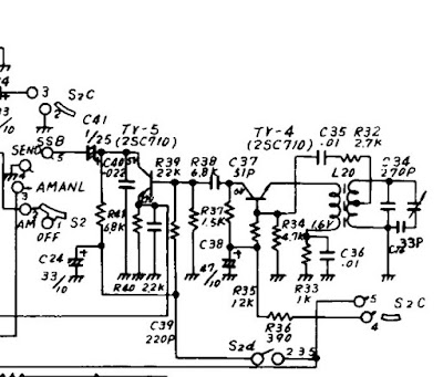
At this point I discovered that while there are many copies of the DX-390 service manual and schematic on the internet, all of them have seriously degraded copy quality right around the parts of the circuitry that I needed to study. Sometimes Murphy overpowers the Radio Gods. It took me a while to get a useful schematic of the BFO control mechanism.

BFO is a bit of a misnomer here: the control actually shifts the frequency of the 55.395 MHz oscillator that drives the second mixer. See Block diagram above). There is a varactor diode in the base circuit of a BLT oscillator circuit. Turning the BFO control varies the voltage going to the varactor thus causing the oscillator frequency to slide up and down. But mine wasn’t moving. And that was a problem.

So I dove right in, trying to figure out why it was oscillating, but not shifting in frequency. At this point I discovered that I too am afflicted with the disease that Pete Juliano suffers from: Fat Finger Syndrome. That BFO control circuit has a nice big 100k pot, but all the fixed resistors and caps were surface mount and SMALL. As I poked around trying to troubleshoot, I managed to make things worse. It turned out that the lead carrying 6 volts to the BFO control circuitry had broken. But before I discovered this, I managed to do all kinds of damage to the board. I lifted two PC board pads (I should have turned down the temperature on my soldering iron). Then, when I tried to fix this, I managed to put a solder bridge across two parts of the circuit that definitely should not have been connected.

This resulted in a bizarre BFO situation. From the center position, turning the BFO to the left OR TO THE RIGHT would move the BFO in the same direction. So I could tune in an SSB station by turning to the right, or by turning to the left. That was just not right.

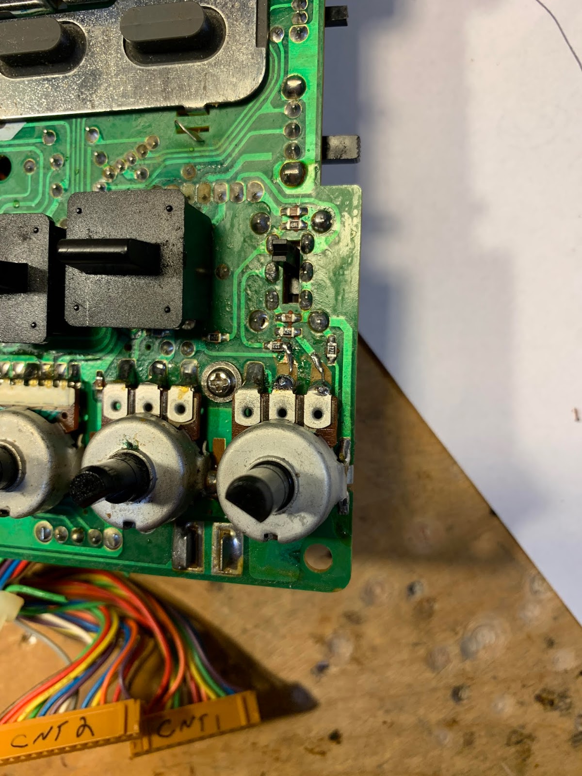
Lifted solder pads. And small wires that now bridge the gaps

Uffff. It took me a while to find that fault. While trying to figure this out, I built the circuit in LTSpice just to see what it was SUPPOSED to be doing. This helped. Eventually, through careful inspection with magnifying goggles, I found a solder blob, and removed it. Now all was right with the universe. Even though I had caused most of the trouble, it was still quite satisfying to fix it.

Some additional observations on the DX-390.

— It really is a Sangean ATS-818 in disguise. Just look at the marking on the PLL board. If you can’t find a decent DX-390 schematic, just use an ATS-818 schematic.

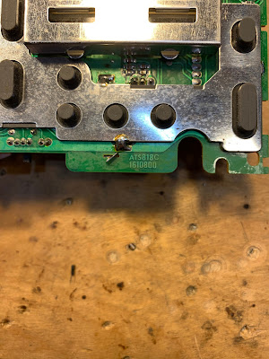
ATS 818 marking along the bottom (green) part of the PLL board

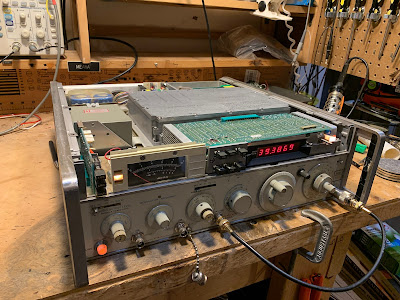
— The service manuals on these receivers are quite good: the include bloc diagrams, detailed alignment instructions, and even voltage charts for all the chips and transistors. Impressive and useful.

— The static discharge vulnerability is hard to understand. There is so much cool circuitry in these receivers, why not add four simple diodes? Not wanting to repeat this saga, I went in and put two sets of back-to-back small signal diodes in each receiver: one set on the telescoping antenna, and other at the input for the external antenna. Curiously, on the newer receiver, it looks like a previous owner had gone in and tried to address this vulnerability — but he did a very incomplete job. He just put ONE diode between the external antenna input and ground. I had always thought that two diodes back to back would give you good protection from static discharge. And I don’t think that single diode protects the front end in any way from discharge coming in from the telescoping antenna.

This was a good project. I got more familiar with general coverage dual-conversion receivers. And I got reacquainted with an old receiver that I liked a lot. Both receivers could probably use some alignment. I’ll take that up next.

Teddy Roosevelt on Homebrewing: “The Ham in the Arena”

“It is not the critic who counts; not the sharp-tongued appliance operator who points out how the homebrewer stumbles, or where the builder of rigs could have built them better. The credit belongs to the ham who is actually melting solder, whose fingers are marked by burns and glue and blood; who strives valiantly; who errs, who splatters and distorts again and again, because there is no homebrewing without error and shortcoming; but who does actually strive to build and improve his rigs; who knows great enthusiasms, the great devotions; who spends himself in a worthy project; who at the best knows in the end the triumph of saying “rig here is homebrew,” and who at the worst, if he fails, at least fails while daring to try, so that his place shall never be with those cold and timid amateurs who never try to build anything, but who only stare at their waterfalls, ready to pounce on those who do.”

See also:


Using SDR without SDR Hardware — N2CQR Adjusts Analog BITX20 using Web SDR

I know what you are thinking: Software Defined radio with the TOTAL elimination of hardware? WHERE IS BILL AND WHAT HAVE THEY DONE WITH HIM?

Relax my friends. All is well at SolderSmoke’s East Coast HQ. In fact, just yesterday I was making use of one of the systems described in this video. Here’s how:

I was on 20 meters with my BITX 20 Hardware Defined (HDR) homebrew transceiver. Everything was going smoothly. We have some sunspots now, so DX is once again possible. I heard a loud U.S. station (that will remain anonymous) calling CQ, so I gave him a call.

The trouble started right after he looked at my QRZ page. You see, I have pictures of my homebrew rigs there. These images sometimes trigger hostile reactions, especially from guys who have almost their entire stations INSIDE their computer boxes. I also admit to occasionally making things worse by pointing out that it is possible to build a BITX20 for about five dollars U.S. Some guys apparently don’t like hearing about this.

Anyway, the fellow I was talking to proceeded to give me a very blunt and harsh signal report: “Well, I suppose your signal is strong enough, but your audio is TERRIBLE!” Interpersonal relations pointer: This is NOT a good way to alert a fellow ham to possible technical problems in the rig that he has built by hand, from scratch, in his home workshop. Especially when the person delivering the harsh signal report is using a “rig” that was built by credit card in a robotic factory on the other side of the planet.

So that QSO ended rather quickly. But I did want to follow-up in the comment about the audio. And here is where I turned to Web SDR. Mehmet NA5B has a really nice WEB SDR receive system in Washington DC, just about 8 miles east of me. Before 20 meters opened, I called up Mehmet’s SDR on my computer, tuned it to the frequency of my transceiver and watched the screen as I asked if the frequency was in use. I then issued a couple of hopeless CQs, again watching the screen. I could see in NA5B’s waterfall that my signal was indeed seriously lacking in low frequency audio.

Now it was time to turn to hardware. Rig on the bench, ‘scope and sig generators fired up, I quickly determined that the problem most likely resulted from my placement of the carrier oscillator frequency in relation to the homebrew USB crystal filter. I had placed it about 300 Hz too low. This resulted in a low AF frequency roll off not at the desired 300 HZ, but instead at around 600 Hz. That would make the audio sound “tinny.” So I moved the carrier oscillator up 300 Hz and went back to Mehmet’s SDR receiver. I could see that the lows were now at the right level. Thanks Mehmet.

One note about the audio coming out of the many SDR radios on the air: When you look at the passbands in the Web SDR receivers you can see audio going almost all the way down to the frequency of the suppressed carrier. With non-SDR rigs you usually see a gap of around 300 Hz between the carrier freq and the start of the SSB signal. This is often the result of our filter rigs having IF filter skirts — you would place the carrier oscillator frequency a bit down the skirt — this would help with opposite sideband suppression and all you would be losing would be the lows below 300 cycles, which weren’t really necessary anyway. I had placed the carrier oscillator too far down on the skirt.

Of course, sometimes SDR rigs will also have a gap between the carrier freq an the start of the audio if the operator has set the passband this way, or if the microphone attenuates below 300 Hz. But you see a lot of signals with audio filling almost the entire passband –some of the “Enhanced SSB” guys are running audio passbands that go as low as 50 Hz.

Has anyone else noticed this “full passband” effect when looking at the waterfalls?
Any other tips for using Web SDR for troubleshooting?

VU3JVX’s Beautiful Homebrew Scratch-built uBITX

When Farhan announced that BITX40 Module boards would no longer be produced, my first thought was that it is, of course, still possible to homebrew a BITX. Anthony VU3JVX proves that in his wonderful description of his uBITX scratch-built homebrew project. Anthony obviously learned a lot — perhaps the most important lesson for new homebrewers is what Anthony did when he couldn’t get the receiver to work: HE TOOK A BREAK and went back after a few days. That is very important.


I also liked very much the fact that Anthony did what Farhan did when the receiver came to life — he stopped building the transmitter and just listened to the receiver that he had built. FB OM.

And three cheers for Anthony’s XYL — she was very wise to suggest that he take on a project like this when he found himself out of work.

Anthony VU3JVX wrote:


I would like to share my journey of building ubitx from scratch, I would also like to dedicate this to Farhan (hope he will read this sometime) as he has always motivated to homebrew stuff.

I got my license ‘VU3JVX’ on March 2017. Passing the exam and getting on HF bands is still two different things. Yes, I started to transmit to local VHF repeater with cheap Chinese Bafong radio, I believe the most economical way to start the ham operator experience. However, I knew that I am missing something since I was not able to operate on HF bands.Coincidentally I saw that bitx40 became available as kit from HF Signals during the same time. I was happy to try it and that’s how I made my first HF rig. Then I came to know about the BITX20 forum and joined the same, one of the best thing I did after buying bitx40. I have learned a lot from all the great people caring and sharing information. I will try to contribute whatever way possible from my side in coming days.

I was already thinking of building bitx40 for other band (because the way Farhan Sir has drawn the schematic it becomes so tempting for DIY) and then ubitx happened and it changed everything. I started studying the ubitx circuit and collecting all the required components, even ordered the exact toroid from W8DIZ website (during my good days and travel to US) but I was not having enough time to put things together on the bench as I am by profession a computer network & security engineer. I was not sure what to do next, during this time my XYL suggested me that why don’t I focus on something which I always wanted to do. And that’s how my journey started to build the ubitx from scratch.


Honestly, I was not sure if this was the right time to start this project. So I started to work on building the receiver segment of ubitx only. I had my challenges during this time and at one point I thought I made a wrong choice of building ubitx, instead I should had tried the bitx40 circuit first. I was almost on the verge to pack up and shelf the project because I was not able to hear anything from the receiver itself forget about building the transmitter. Then took a break for few days and then started troubleshooting each segment one by one. Finally I found it after reading through the bitx20 forum that my Q70 to be defective then I also came to know that is it better to replace it with audio type transistor 2sc945.
I believe during this process I have read most of the content on bitx20 forum. Some name which repeatedly comes to my mind are Raj (vu2zap), Allison, Jerry and thanks to all other hams out there. I had all the version schematics but started my work based on V5 and wanted to get the best out of all the version so I kept the build approach modular and laying them almost like the schematic for easy troubleshooting (you can see those pic on my qrz page).

Next challenge was trying to be too good student and follow everything the master said (pun intended). I made a cocktail of 12 Mhz with 11.059 Mhz crystal filter (Farhan Sir I believe the schematic is still showing X7 as 12 Mhz) and after changing the X7 to 11.059 Mhz I was able to see the radio signal making it through the crystal filter, then came the next hurdle of fine tuning the USB and LSB and fiddling with the software for the right value. After the receiver started working I took a break from building the radio and started enjoying the receiver and checking all bands. One evening I narrowly missed Farhan ji on air but anyway I would not have been able to communicate with him since my ubitx transmitter was not ready.
After that day I thought of building the ubitx transmitter soon. I was quiet confident about the transmitter build by this time and thought it should be straight forward. Logically yes it should had been that way but I was so wrong. Following all the recommendation from the forum about harmonic issue and how to avoid them I started building the BPF. Then I started to work on the PA section then came tuning the IRF510 current (I call it “Bell the cat moment”) luckily I never blew any IRF510. However, the output watt on 40 M was hardly 2-3 Watts and other higher band less than 1 Watt. I knew something was wrong with those MOSFET but out of circuit the test look normal. I had some other stock from different source even those performed the same. Played around with different PA transformer settings and checking/tracing the RF signal. Everything looked normal till IRF510. Chances of fake IRF510 is less (as debated on the forum) as it is not an expensive RF part like RD16HHF1. Now I was confused, I had some spare new RD16HHF1 which I got online, which I was not very hopeful thinking that it might be fake. I thought of giving it a try (pin layout configuration was easy for me as I have taken the island cutting approach on single side copper board).

Voila ! I got a whopping 10+ Watt 40M, 5W on 20, 10W on 17M, 10W on 15M, 5W on 12M and 10M. Yes there are lot of fake IRF510 out there. Now it was time to test the homebrew rig on air, checked in at evening into All India Net and got 59 report and the net controller thought I am using commercial rig. Finally during these difficult time in my personal life I was able to smile and sleep well that day. The icing on the cake was installing the Nextion 3.5 display (If I remember correctly this is single most expensive component in the radio and thankfully it is optional).

Does that mean everything is 100% with my home brew ubitx ? Nope, I am still trying to figure out the feedback issue from the speaker during transmit. I traced the issue and found the audio leaking from emitter of Q6. I would like to mention that I tried all the audio circuit and finally settle for TDA2822 circuit. However, the issue is still there during transmit so I have made the audio circuit offline during transmit, I know this will impact my CW listening while transmitting when I upgrade my license . I have exhausted all solutions from Bitx20 forum but still no luck. I would be happy is someone can point me to the right direction. I would be also happy to share any information related to my build or the software settings/tuning, yes I like programming especially ‘C’ so I am comfortable with Arduino programs. I am thinking of building another PA module with IRF510, I personally feel IRF510 (I got the original finally) has made the home brewing so interesting.

Anthony VU3JVX


For All You Guys Who DON’T Use the Proper Fuse Value

Pete has been trying to talk sense on this issue for a long time, but some folks just won’t listen.
You need to have a reverse polarity protection circuit in your rigs AND you need to carefully determine fuse size needed for normal operation. If your final transistors for some reason start pulling more than the normal amount of current, the fuse will blow before your PA transistors release their smoke.

SolderSmoke Podcast #210 Boatanchors, Magnetostriction, VFOs, AM, CW, SSB, Mailbag

2 March 2019

SolderSmoke Podcast #210 is available:

http://soldersmoke.com/soldersmoke210.mp3

Alexa, Marie Kondo, berets, and ham radio

Bi-Coastal Boatanchors
BATTLE CRY: The Vintage SSB Preamble! “We are NOT ashamed!”
Bill’s HT37 and Drake 2B
Pete’s National National NCX-3 TRGHS
Mechanical Filters
Magnetostriction
Why did Collins go with mechanical vice crystal filters?
The foam deterioration syndrome in mechanical filters. Sad.
Please send any unwanted Mechanical Filters to Bill.
BONUS QUESTION: Look at the filter below. What is different/special about this one?

Pete’s antenna trouble
Pete’s FB amplifier troubleshooting
Recent improvements in the uBITX finals
Pete’s design for a VFO for Bill (and an indoor antenna tuner!)

Bill’s VFO for Pete: HRO dial and gearbox driving a rotary encoder

Guido PE1NNZ puts the QCX on SSB
“The Secret Life of Machines — Radio”
HB HRO dial from DL6WD
WA1QIX’s USB D-104
“The High Frequency Oracle”
DeMaw’s LC filter receiver
Godzilla and Ham Radio
Bill’s poor quality SSTV images from space (what happened?)
Listening to AM on an SSB receiver
Mixed feelings about CW

MAILBAG
M0KOV’s mom took him to the doctor due to THE KNACK.
M0JGH getting married (ALWAYS LISTEN TO PETE!)
Jac’s FB Receiver

What is different/special about this one?