Can a Biologist Fix a Radio?

Andreas DL1AJG (who in real life is a professional biologist) sends us this excellent article about how biologists approach problems in living cells as opposed to how engineers or technicians approach problems in broken radios.

This excerpt from the 2002 article gives you an idea of the tone and content of the article:

“… I started to contemplate how biologists would determine why my radio does not work and how they would attempt to repair it. Because a majority of biologists pay little attention to physics, I had to assume that all we would know about the radio is that it is a box that is supposed to play music. How would we begin? First, we would secure funds to obtain a large supply of identical functioning radios in order to dissect and compare them to the one that is broken. We would eventually find how to open the radios and will find objects of various shape, color, and size (Figure 2). We would describe and classify them into families according to their appearance. We would describe a family of square metal objects, a family of round brightly colored objects with two legs, round-shaped objects with three legs and so on. Because the objects would vary in color, we would investigate whether changing the colors affects the radio’s performance. Although changing the colors would have only attenuating effects (the music is still playing but a trained ear of some can discern some distortion) this approach will produce many publications and result in a lively debate…”


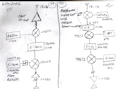
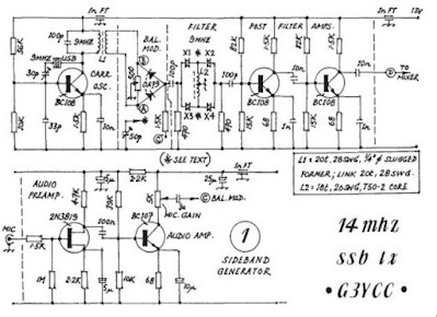
Andreas points to diagrams in the article (see below). The first (A) shows how the biologist might view the radio. The schematic (B) shows how engineers or technicians view it:

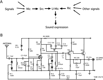
As I read the article, I was reminded of the wise advice frequently dispensed through the SolderSmoke podcast: Do not look at a schematic as one single circuit. Instead try to see it as a number of subcircuits. Build and test these subcircuits separately. Join them together only after each subcircuit is found to be working.

Here is the link to the 2002 article in Cell by Yuri Lazebnik: https://www.cell.com/fulltext/S1535-6108(02)00133-2

This is all really interesting. I will share this with my son who is involved now in biological research.

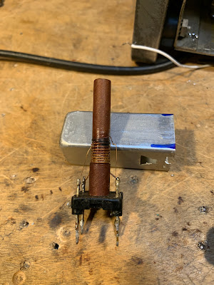
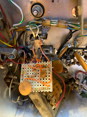
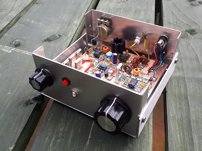
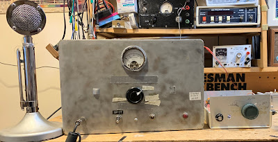
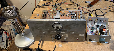
In addition to his day job as a biologist, Andreas is a homebrewer of radios. Here is a pictures he sent to us back in 2019 of a regen receiver that he built:
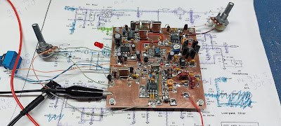
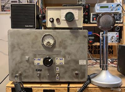
Andreas asks if he might need an old Boatanchor radio to work on to improve his electronics/physics skills. I’d suggest staying away from the older tube stuff. Stick with the BITXs — homebrew one, stage by stage. And indeed, use the engineering approach to the electronics!

Repairing the Sony ICF SW1 Receiver — Used for Numbers Station Reception? Why no replacement for C-625?

Ten years ago, my friend John gave me this tiny Sony receiver. It wasn’t working. I tried to fix it but quickly discovered that the tiny size of the device made repair difficult. All you needed to do was to swap out some leaking electrolytics, but they are surface mount electrolytics — replacing them is not for the faint of heart. Kits are available, but again, this is not easy.

In 2020 I got one of the kits, but didn’t try to use it until yesterday. It only supplied six of the electrolytics. In the video above, they discuss replacing seven electrolytics, including the one that seems to be placed in the round black holder. C-625. Why didn’t my kit include a replacement for that one? Could it be that this capacitor was not one of the leaky SMD caps?

Replacing these caps really wasn’t easy. At one point I inadvertently removed not just the bad cap, but also a nearby surface mount resistor. Luckily the schematic showed it to be 0 ohms. That was easily replaced. I lifted one of the pads on one of the other caps — I just slid it back into place and hoped for the best.

BTW, I just today discovered that this little receiver may have been used late in the Cold War by those who needed to receive messages from the infamous Numbers Stations:

https://www.cryptomuseum.com/spy/sony/icfsw1/index.htm

Troubleshooting and Fixing Old Faults in my Long-Suffering Hammarlund HQ-100 (Part 2) (video)

Work continues on my old Hammarlund HQ-100. I give background on the rig and explain the electrical trauma it likely suffered. Following Dave K8WPE’s dictum that we can still learn a lot from old receivers, I dug into this one. I wanted to fix a long-standing S-Meter/AVC problem. This led me to an interesting troubleshoot, with at least one “waste of time” detour. Eventually I found the fault in one of the coils in the grid circuit of the RF amplifier. The coils had been smoked years ago, perhaps by a lightning strike. I came perilously close to permanently losing 10-30 MHz. But I figured out how to fix the smoked coil. So my S-Meter/AVC problem was fixed. I really like listening to this thing. There is still a lot of nice material on the SW bands. There are some very nice broadcasts in Spanish. Please subscribe to my YouTube channel.

You can see where the coil burned. Wire remained intact, but the insulation burned creating a Primary to Secondary connection.
I just very carefully lifted one of the coils way from the other, eliminating the unwanted connection.
Here’s my homebrew “RC Printed Network” Z2 module. This was unnecessary — the original was good. I put the original back in.


Electric Radio magazine recently ran a two part series on the HQ-100. I have ordered these issues of the magazine.

WD-40, a Hard Drive, a Coat-Hanger Antenna, Dumpster Diving, and Amateur Radio Satellites from the Azores


Last month I was talking to Ira VP2EIH on my new 1712 SSB rig. Ira is interested in satellites. Talking to him caused me to dig up some old material about satellite operations. Here is a 2003 QST article about working the satellites from the Azores:

Regarding the usefulness of WD-40, during my time in the Azores John EI7BA once told me that WD-40 is, “the Pope’s pee!” Apparently that is high praise in Ireland. It is indeed good stuff.

Messias CU2BJ is a Silent Key. I hope Ray CU3GC, WL7CDK is doing well.

Colin M1BUU’s Homebrew Manhattan SST

Wow, especially on St. Patrick’s day I think it is appropriate to say ” ’tis a thing of beauty. “

Colin did a great job on his homebrew version of the SST transceiver. It looks like his is on 30 meters. I especially liked his description of the troubleshooting that followed the construction. the assist provided by AA7EE’s blog was especially cool, and demonstrates the long-lasting power of internet-shared tribal knowledge.

Colin wrote (on Facebook):

I was inspired by Bill and his adventure with the SST-20, so I started gathering a few parts last year to build a Manhattan SST. I did a joint SOTA activation with a fellow homebrewer ham at the end of January and we started talking about classic portable CW rigs, it turned out that we both had an SST build on our ‘list’. I was challenged to build the SST for the next joint SOTA activation!
It took a lot of effort and a few late nights but I did manage to produce a rig capable of making QSOs for a joint SOTA activation of Fair Snape Fell, G/SP-007. I’d done a solo activation of Pendle Hill G/SP-005 a few days before with the rig for a trial run and I discovered that the AF was very low. After some troubleshooting I noticed that I’d soldered the LM386 gain set capacitor to an incorrect pad. Doh! I fixed my error and the rig had much more gain.
I found that with the improved AF gain, the rig would squeal if the gain was turned up. I was ready to give up really, but after a cool off period, I began researching the issue and it turns out that it’s very common and indeed I found posts from 1997 about it! It seems as though my recreation was so faithful to the original, I’d included the original flaws too! I added in a 0.1uF cap and resistor connected to pin 5 of the AF amp chip as per the suggestion on Dave AA7EE’s blog and now the squealing has stopped.
I’d made 14 QSOs during the joint SOTA activation, so I considered my challenge to have been met! It’s been a bit of an epic build!
73, Colin, M1BUU

SolderSmoke Podcast #235 NE-602, Azores Rig, Spur Problems, SSB Rigs, Peashooter, HB Filters, MAILBAG

SolderSmoke Podcast #235 is available for download:


http://soldersmoke.com/soldersmoke235.mp3


Travelogue:

6 weeks in the DR for Bill
One contact on uBITX. More SW listening.
Repaired my Chrome Book in Santo Domingo!
Christmas Present for All: James Web Space Telescope launch


Bill’s Bench
— Understanding the NE-602 (see blog post)
— Thinking about a 17/12 dual bander. Looked at old G3YCC Tx for circuits…
— Using Spurtune08. WB9KZY found it. In the LADPAC zip file here:
— Then Put G3YCC Acores SSB TX back in operation
— Now working many stations with this old “split” TX/RX

Pete’s Bench
— Dean’s VWS build of your DC RX
— Homebrew Crystal Filters
— The shrinking of the PSSST

Bad Dead Soldering Stations
— My X-Tonics 4000 dies. But it left behind a great box with ample socketry.

Mailbag:
AA1TJ Mike Rainey — Again in the Hobbit Hole! 486 kc RX
Thomas K4SWL — Radio Astronomy and the Raspberry PI
WC8C Dennis Invite to the L’Anse Creuse ARC FB Fun
Todd K7TFC got boosted at Tektronix Beaverton Ore.
What happened to Chuck Adams K7QO? His work taken off the net.
W1MJA ex WN2RTH
N7DA worked W7ZOI in Sweepstakes. FB
Kirk NT0Z formerly of ARRL HQ
Farhan VU2ESE was up in the Pench Forest, trying to spot a Tiger!
We spoke to Farhan’s Lamakaan ARC in Hyderabad. QO-100 beam down!
Dean KK4DAS’s 16 watter. On SS blog
Scott WA9WFA Bad 6U8s? Ordering 6EA8s
Bruce KC1FSZ Peppermint Bark gift box
Bob Scott KD4EBM So many good ideas and links
Rogier PA1ZZ sending parts packages — Thanks Rogier

Exorcism Lite — Spur Suppressed on 17 meter Transmitter — Split TX/RX Station On The Air

I spent most of January in the tropics, away from my workbench. This seems to have had a good effect on my 17 meter split TX/RX project. As I was leaving, heading south, I was thinking about several difficult options to deal with my spur problem (see previous blog posts). I thought about turning the transmitter into a transceiver by building a receiver board. I thought about putting San Jian frequency counters on both the transmitter and the receiver, then doing a visual numerical “netting” by just putting the two devices on the same frequency (I actually ordered 3 San Jian counters). The counter option was even more complicated than it at first seemed — I would have to build a converter to shift the RX VFO frequency up. VK2EMU suggested a tube type “Magic Eye” (interesting idea, but also complicated). This was getting out of hand.

When I got back home, I took a new look at the problem. I decided to take one more shot at suppressing the 8th harmonic of the carrier oscillator. I had already built a new oscillator and buffer using the circuit from Farhan’s BITX20. And I had put it in a metal box. Now I decided to do three things:

1) Tighten up the low pass filter at the output of the buffer by moving the cutoff frequency lower (to around 7 MHz) thereby getting a bit more suppression at 41 MHz

2) Try putting a series LC shunt circuit tuned to 41 MHz at the output of the carrier oscillator (between the oscillator and the buffer).

3) Reduce the voltage to the oscillator/buffer. I have this on a pot, so I can adjust it down to the point where the remnant of the harmonic is no longer audible, while keeping the main carrier osc signal sufficiently strong.

It seemed to work. I could now hear the desired frequency for spotting, without the confusing tone from the spur.

Why had I been able to do this back in 2002 in the Azores using a simple trimmer cap to ground? My guess is that I was using my Drake 2-B as the receiver. The trimmer cap to ground may have reduced harmonic output. And I was probably cranking back the RF gain on the 2-B to the point where I could hear the desired signal but not the remnants of the spur. I have no RF gain control on the Barebones Barbados receiver that I am using in this project.

So, what’s the lesson from all this? Well, if you are faced with a serious technical problem, and you find yourself considering complicated and difficult solutions, go to the Dominican Republic for about a month (especially if it is January or February), and then take another look at the problem when you return. If you are unable to travel this far or for this long, taking a walk or taking a weekend break from a troublesome problem will likely have a similar mind-clearing effect.

The video above shows part of a February 1, 2022 QSO with Gar WA5FWC using the split TX/RX 17 meter rig. Gar is an amazing long-time SSB homebrewer who got his start with phasing rigs back in the day.

Exorcism Not Quite Complete — Thinking of Other Options

As often happens, I may have jumped the gun in declaring the exorcism of my 17 meter transmitter to be a success. As readers of this blog will recall, my problem was that when trying to “net” my separate 17 MHz receiver and transmitter, at around 18.116 MHz I could hear more than one tone as I tried to get to zero beat. The 8th harmonic of my 5.176 MHz carrier oscillator was mixing with the 23 MHz VXO signal and producing a spur. I could probably knock the level of this spur down below FCC limits, but — and here is the problem — I probably could never knock it down to the point that it would not be audible in the sensitive receiver that sits right next to the transmitter. So this is really a netting problem, not really a spur problem.

I don’t want to try another filter frequency — I have VXO crystals that really work only with a filter at 5.176 MHz.

So here is my current idea: Build a receiver board and turn this thing into a transceiver. Switch with relays the input and output of the 5.176 MHz filter, and use relays to switch to the receiver board the VXO and carrier oscillator signals.

Making this thing a transceiver would eliminate the need for netting. This should solve my problem.

What do you folks think?

73 Bill

Exorcism Completed! Getting Rid of the Spur in my 17 meter SSB Transmitter using a TinySA (video)

To re-cap: The problem became evident when trying to “net” or “spot” my transmitter onto my receive frequency. Around 18.116 MHz, I could hear at least two tones in the receiver as I moved the transmitter frequency. I needed to get rid of the extra tone.

First, thanks to all who sent in suggestions. They came in literally from around the world, and this is a demonstration of the IBEW in action. I used or at least tried all of them. They were all good ideas.

Following Vasily Ivananeko’s pseudonymous suggestion I rebuilt the carrier oscillator (apologies to G3YCC). I used the carrier oscillator/buffer circuit from Farhan’s BITX20.

Henk PA0EME said I should look at the signal level at the input ports of the NE602 mixer. Henk was right — the VXO input was far too high. I lowered it, but the problem persisted.

At first, I thought that the spur in question was so small that it would not show up on the air. I could not see it in the TX output using my TinySA spectrum analyzer. That was good news and bad news: Good that it was not showing up on the air, bad that I could not see it in the TinySA and use that image in the exorcism.

At first I thought that the spur was being caused by the 10th harmonic of the carrier oscillator and the third harmonic of the VXO. This seemed to fit. So, following VK3YE’s sage advice, I built a little 69 MHz series LC trap (using a coil sent by AA1TJ, on a board CNC’d by Pete N6QW). That trap succeeded spectacularly in crushing the 10 harmonic. Look at these before and after shots on the TinySA:

Before Trap
After Trap

Spectacular right? But guess what? The problem was still there.

I scrutinized the situation once more. I realized that the spur would be more visible if I put the TinySA on the input of the transmitter’s PA (a JBOT amp designed by Farhan) as opposed to putting it on the output. Watching the spur and the needed signal move in the TinySA as I tuned the VXO, I realized that they were moving in opposite directions. This indicated that the spur was the result of a carrier oscillator harmonic MINUS a VXO-generated frequency (as the VXO frequency increased, the spur frequency decreased). Looking at my EXCEL spread sheet, I could see it: 8th harmonic of the carrier oscillator MINUS the main output of the VXO.

To confirm this, I plugged the values into W7ZOI’s Spurtune program. Yes, the spur popped up and moved as predicted.

For further confirmation I shut down the carrier oscillator by pulling the crystal from the socket, and then just clipped in a 5.176 MHz signal from my HP-8640B signal generator (thanks KB3SII and W2DAB). Boom! On the TinySA, the spur disappeared. Now I at least knew what the problem was: a harmonic from the carrier oscillator.

Following good troubleshooting practice, I turned off the gear and went to bed. When I woke up, an idea came to me: Before launching into a lot of filtering and shielding, just try running the carrier oscillator at a lower voltage, seeing if doing so might reduce the harmonic output. I disconnected the carrier oscillator board from the main supply and clipped in a variable voltage bench supply. Watching the signal on my TinySA, I watched as the spur completely disappeared as I reduced the voltage from around 13V to 10V (see video above). The main signal frequency level did not change much. I tested this by listening for the hated extra tones. They were gone. Exorcised.

Key lessons:

— Spur problems are difficult to troubleshoot. Armstrong’s superhet architecture is, of course, great, but this is definitely one of the pitfalls. Single conversion makes life easier. IF selection is very important. Choose wisely!

— When looking at the TinySA as you tune the rig, pay attention to which way the spur is moving. This provides an important clue regarding the combination of harmonic you are dealing with.

— The TinySA is a very useful tool. It seems like it is easier to use than the NanoVNA (which is also a fantastic tool).

— It can be fun and rewarding to re-visit old projects. In the years between original construction and the re-look, new test gear has become available, and the skill and experience of the builder has improved. So problems that once seemed insurmountable become fix-able.

— Thinking through a problem and thinking about possible solutions is very important. It pays to step away from the bench to think and rest. Rome wasn’t built in a day. Here’s a rough block diagram that I drew up (noodled!) while trying to figure out this problem:

Troubleshooting Apollo: 23 MHz Crystals in a NASA Ground Receiver

More amazing Apollo stuff from CuriousMarc.

Here we see them struggling to find the proper frequency for one of the oscillators in a dual conversion UHF receiver from the Apollo program. For the VCO, they needed a crystal in the 23 MHz range. They faced the same questions we face: Series or parallel? Load capacitance? Fundamental or overtone?

It just so happens that at this moment I have on my bench the 17 meter SSB transmitter that I built some 20 years ago. And the VXO in it uses crystals in the 23 MHz range. TRGHS. (More on the spur problem with this rig soon. The solution does involve the 23 MHz VXO.)

Very cool that CuriousMarc found a manufacturer still willing to produce custom-made crystals. JAN flashbacks! LapTech Precision in Canada: https://www.laptech.com/index.php
The video above is Episode 8 in the Apollo Comms series. If you go back one episode, you can watch Marc and his assistant troubleshoot the NASA Apollo UHF receiver. They use very familiar troubleshooting techniques. This reminded me a lot of what we do with older, potentially modified gear. They were able to figure out what was wrong and how a mod had changed things. This set the stage for the crystal replacement selection we see in Episode 8. Here is Episode 7: https://www.youtube.com/watch?v=87qA41A_Ies
Note: The frequencies in this Apollo receiver were listed in Megacycles, not Mega Hertz.

Thanks to Bob Scott KD4EBM for alerting us to this.

How to Fix the Spur Problem in my 17 Meter SSB Transmitter?

I built the transmitter almost 20 years ago. It is in the larger box, which originally housed a Heathkit DX-40. There is a lot of soul in that old machine. Details on this construction project are here: https://soldersmoke.blogspot.com/2021/12/junk-box-sideband-from-azores-2004-qst.html (The smaller box is a Barebones Superhet receiver set up for 17 meters.)

In the 2004 QST article I discuss a problem I had with “spotting” or “netting.” This is something of a lost art, something that you had to do back in the pre-transceiver days, when running a separate transmitter and receiver. This was how you got the transmitter on the receiver’s frequency. Essentially you would turn on the carrier oscillator and the VFO and let a little signal get out, enough to allow you to tune the VFO until you heard zero beat on the receiver. My problem was that around one particular frequency, I would hear several zero-beats. This made netting the receiver and the transmitter hard to do.

Important note: This is really just a problem with the “netting” or “spotting” procedure — the problematic spur does not show up in any significant way in the output of the transmitter. I can’t see it on my TinySA. But it is strong enough to be heard in the unmuted receiver sitting right next to the transmitter. And that creates the netting problem.

In the QST article, I said that I noticed that the problem seemed to be centered around 18.116 MHz. As I approached this frequency, the tones — desired and unwanted — seemed to converge. That was an important clue. In the article I said I thought that I could eliminate the problem with just one trimmer cap to ground in the carrier oscillator, but looking back I don’t think that this really fixed the problem.

I recently took a fresh look at it. Exactly which frequencies were causing the unwanted signals that appeared in my receiver?

I used an Excel Spread sheet to find the culprits.

The first column shows the carrier oscillator and its harmonics. The second column shows the VFO when tuned for a signal at 18.11668 MHz (23.2927-5.17602), along with its harmonics. Check out the 10th harmonic of the carrier oscillator and the third harmonic of the VFO: 69.8781-51.7602 = 18.1179. Those two harmonics would produce the problem I had been experiencing.

I turned to one of Wes Hayward’s programs for confirmation. Spurtune08 came in the EMRFD software package. Here is what I saw when I plugged in the above frequencies:
You can see the little spur off to the left of the main signal. In the program, as I tune the 23 MHz VFO frequency, the spur moves closer to the main frequency as I approach 18.116 MHz, just as it does in the real rig. Note that I have only turned on the 10th harmonic of the carrier oscillator and the 3rd harmonic of the VFO. Spurtune08 is very useful. Thanks Wes!
So, what is to be done? For now, I am just restricting my operations on 17 meters to above 18.120 MHz. (I worked several DX stations with it on December 27.) But obviously I need to fix this. This rig needs an exorcism. I think I only need to get rid of one of the harmonics, and the 10th harmonic of the carrier oscillator seems easier to kill. I’m thinking of putting the carrier oscillator in an Altoids box, and then adding some filters to knock down the 10th harmonic.

Here is the G3YCC schematic that inspired this rig. I used G3YCC’s carrier oscillator and balanced modulator circuits, just using a 5.176 MHz crystal and changing the tank circuit in the collector:

How would you folks knock down that 10th harmonic?

Right to Repair Update

Allan WA9IRS sent me this article. Thanks Allan.

https://www.digitalengineering247.com/article/right-to-repair-movement-attracting-attention?oly_enc_id=4802E9408878H3Y

The French “repairability index” is an interesting concept. I wonder how modern ham radio “radios” would score. I think our homebrew rigs would max out the index.

Pete has commented on manufacturing processes that do (or don’t) factor in access for repair.

One of the recent horror stories we’ve heard is about a certain manufacturer of mobile phones. It seems that they have designed the phones so that if you dare to replace a broken screen, the new screen won’t work unless you de-solder the associated chip, then re-solder in the SAME CHIP.

Previous blog posts on this:

https://soldersmoke.blogspot.com/2010/11/knackers-of-world-unite-you-have.html

https://soldersmoke.blogspot.com/2021/03/mending-vs-ending-fight-against-planned.html

SETI, Proxima Centauri, The Parkes Dish, and Intermodulation Distortion?

https://www.sciencealert.com/exciting-mystery-space-technosignals-were-indeed-produced-by-sentient-life-us

A cosmically interesting troubleshoot. But I’m not sure about their explanation. Why would the intermod disappear when they moved the Parkes Radio Telescope off of Proxima Centauri?

No Longer On the “Shame Shelf” — Pete Fixes His KWM-1

I think a good troubleshoot is almost as satisfying as a successful homebrew. And we can sense that high level of satisfaction in Pete N6QW’s description of his repair of a Collins KWM-1:


I liked Pete’s troubleshoot/repair story, but — as is often the case — I struck by his turn of a phrase. I think Pete has added something important to the SolderSmoke lexicon:

THE SHAME SHELF

Most of us have a shelf like this. I have an HW-101 on mine. Pete shows us that there is hope — there is path off of the shame shelf. You just have to know stuff…. Or have IBEW friends like Pete who can advise you.

Scott WA9WFA’s Mate for the Mighty Midget Receiver is WORKING! (Video)

Wow, Scott got his Mate for the Mighty Midget receiver to work and he is obviously overjoyed with the result. All of us who have struggled with a homebrew project know just what this feels like. And it is very cool that Scott got some useful guidance from Charlie Morris in far-off New Zealand. Congratulations Scott. I’m really glad you stuck with it.

Scott’s success comes at a good time: Pete N6QW is building W4IMP’s three tube “IMP” SSB transmitter (also from the 1960s). I accept responsibility for naming Pete’s project: It will be known as “Pete’s IMP” or, memorably, “The PIMP.” For a look at Pete’s rig go here:

Scott had problems getting Lew McCoy’s 455 kc crystal filter to work. So did I. It turns out that this is a very old problem, going back to World War II. In Don Stoner’s 1959 “New Sideband Handbook” on page 54 he writes of homebrew filters in the 400 to 500 kc range:

“Inexpensive crystal filters constructed from war surplus FT-241 type low frequency crystals are very popular with the ‘do it yourself’ hams. These CT cut crystals have been plentiful and relatively cheap for a number of years and are in the hands of many Amateurs. The general run of war surplus crystals may or may not be good. Experience has shown that one out of four of these crystals are usually defective in one way or another.”

Stoner was writing just 14 years after the war. Add another six decades to the age of these crystals — often decades spent in musty basements — and you can imagine the percentage of bad 455 kc FT-241 crystals increasing. So I think Scott is wise to seek an alternative to McCoy’s crystal filter.

Scott’s original build of the MMMRX receiver is just so nice. In the video he says he plans to go back to it after he gets the expanded version fully functional. He should definitely do that — his original version looks so good. I think it is probably very close to working properly.

Thanks Scott, and again, congratulations OM.

The Joy of Fixing Broken Things (a really amazing video)

This amazing 10 minute video captures very well the joy of fixing broken things. It comes to us through a recommendation from Paul VK3HN in Melbourne, Australia. Thanks Paul.

I hope we will see more from Van Neistat. He already has a bunch of videos on his YouTube channel: https://www.youtube.com/channel/UC5mPJA4y5G8Z6aNkY6AxgAw

I often tell the story of the OT (probably now an SK) who at hamfests would ask if a piece of old gear was working. If the vendor answered honestly and said no, OT would reply, “Good, I pay extra for that.” He too liked to fix things.

Mending vs. Ending — The Fight Against Planned Obsolescence

We don’t get a lot of mail from Darwin, Australia, so the message coming in from Phil VK8MC immediately got our attention. When I looked into the details I realized that it was very SolderSmoke-relevant. The Guardian article that Phil cited even mentions hobbyists tinkering with electronic devices in their sheds (that would be us!). Phil points to the connection between our repair efforts and the struggle to save the planet: “It’s not just a hobby, it’s an ethical position which contributes to the well being of the planet. A higher calling indeed!”

Here is the article Phil pointed us to:

https://www.theguardian.com/commentisfree/2021/mar/17/ending-over-mending-planned-obsolescence-is-killing-the-planet?CMP=Share_AndroidApp_ProtonMail

The poster above (which hangs above my workbench) is from https://www.ifixit.com/Manifesto.

Repairing My Maplin Audio Waveform Generator

I picked this generator at the Kempton Park rally in London many years ago. I use it quite a bit, not only for circuit testing but also as an easy way to get my homebrew BITX rigs to send a signal so that I can adjust my antenna. I just plug this thing into the mic jack, crank in a small amount of 1 kHz audio, and I am ready to minimize SWR.


It never gave me any real problems until last week. I opened it up and examined the circuitry for the first time. Lots of mystery chips in there. Fortunately they are all socketed. Thank you Maplin.

Even without really knowing how each of the ICs work, it was easy to troubleshoot. See the schematic in the article that begins on page 21 in this .pdf:


My Rigol scope showed a good signal going into and coming out of IC8, the LF351 op-amp. From there the signal goes to IC5 a 4066BE. But nothing was coming out of IC5. Thus IC5 was my lead suspect. I put in a quick order to Digikey. A couple of days and a few bucks later the chips (as always, I ordered several) were on my doorstep. Within a few minutes IC5 was replaced and the generator was as good as new.

One annoying problem with this generator is that it has no automatic shut-off circuitry. So if I forget to turn it off, I soon have to buy two 9V batteries. Tony G4WIF suggested a simple timer circuit. I may do that soon. Or, given that we are already on the IC dark side with this project, there is this: https://www.youtube.com/watch?v=C4C2H_3BU3o&feature=youtu.be

I recently find myself replacing a lot of chips in various rigs and devices in my shack. It seems that chips go bad more frequently than discrete transistors or even tubes. But maybe I’m just using older gear with older, more fragile chips. What do you folks think?

SolderSmoke Podcast #228

Soldersmoke Podcast #228 is available:

Of course, no travel. But vaccines are here so maybe soon we can leave our shacks.

In the meantime:

I’ve been playing chess against AI bots on chess.com.

Netflix recommendation: The Bureau. From France. A review from NPR:

https://www.npr.org/2020/06/22/881642358/addictively-suspenseful-thriller-series-the-bureau-will-keep-you-on-edge

A reading from “Conquering the Electron.” Germanium vs. Silicon.

Bill’s Bench:

The KLH Model Twenty-one II. Acoustical Suspension. First receiver WITH A PILLOW! Bad speaker? Blown AF amp finals. Hot heat sink. VBE Multiplier. Desitin.

Tony Fishpool’s recommended LM386 boards. 10 for 11 bucks. Nice. They work. Pictured in the Amazon ad at the upper right of the SolderSmoke blog page.

Putting a digital display on the Lafayette HA-600A

Test gear trouble. My Radio Shack multimeter getting flaky. I many need something better. Auto ranging? My beloved Maplin AF generator died – will have to fix. I need that thing. Probably a bad chip. Good thing they are socketed.

I almost forgot about SKN! But I remembered and I made one contact with the HT-37 and Drake 2-B.

Pete’s Bench:

Presentation to RSGB on Homebrew.

TenTek Troubleshoot.

Swan 240? Looking nice.

SDR adventures.

MAILBAG

Bill N8ET sent me some really nice Showa 9 MHz 8 pole crystal filters.

Kevin AA7YQ Smoke jumper! Building a hybrid SDR.HDR rig. Launched blog. FB

Nick M0NTV working on similar HDR/SDR project. Great video.

Grayson KJ7UM Hollow State Design – Launched a new blog. Very FB!

Thomas K4SWL of SWL Post blog. Kearsarge Mountain Transmission system. And recent events.

Peter VK2EMU Poetry. CW poetry.

Pete WB9FLW looking at DSB rigs…

Drew N7DA Feels not like a real ham because he hasn’t built a quad from bamboo. Which type of landscape bamboo is best for antennas?

Ryan Flowers of MiscDotGeek.Com blog is also watching the Tally Ho YouTube videos of Leo Sampson. Wants to put a WSPR beacon on the Tally Ho.

Joe KF5OWY Working with diode ring mixers, trying to see the mixer action on his ‘scope. 1 and -1!

Jim AB9CN sent a cool idea about how to do a 20/17 Moxon.

Roy GM4VKI – I thanked him for his article in SPRAT about putting a 2n3904 on the output of an NE602 10P mod. Brilliant.

Roger Hayward Told him that I really liked his Dad’s recent web site updates.

Farhan – Jokingly cursed me for showing him the Oscillodyne regen of Hugo Gernsback and Jean Shepherd. “Now I will have to build this!”