
This short video shows how I used my new FeelTech Signal Generator (90 bucks shipped from China) and my trusty Rigol oscilloscope to display the passband of the filter in my Armand HROish receiver. Feedback on this test procedure would be appreciated.
Category: test gear
SolderSmoke Podcast #190: Pilgrims, Junkbox rigs, BANDSWEEP, Matching xformers, On the Air with HB, MAILBAG
SolderSmoke Podcast #190 is available:
http://soldersmoke.com/soldersmoke190.mp3
Pilgrims’ Progress: Inspiring words from G3RJV
BENCH REPORTS on JUNKBOX RIGS:
Pete describes his beautiful 40 meter blue transceiver (video above)
Bill describes his “Armand HROish” receiver
BANDSWEEP!
Bill needs small (yellow slug) 455 kc transformers.
We need a good user-friendly 40673 SPICE model.
SEND US YOUR BENCH REPORTS!
The BD139 transistor
Ferrite Core Matching Transformers
QSO Reports: Getting on the air with HB rigs
Bill’s new FeelTech Signal Generator
MAILBAG

My New Chinese Signal Generator
More amazing low-cost test gear from China. Elisa gave me this device on the occasion of my completing another solar orbit. Amazing capability for less than $90. The video above gives you a good sense of what this thing can do.
I have already had success with the freq generator function. The frequency counter also works great. The sweep function looks very useful for filter checking. And the ability to generate square waves at different phase relationships will be very useful in phasing receiver and transmitter projects.
This little box should help me eliminate a lot of clutter on the work bench. And it looks good next to the Rigol ‘scope.
Mine came from Amazon:
https://www.amazon.com/gp/product/B01A8S4TZK/ref=oh_aui_detailpage_o00_s02?ie=UTF8&psc=1
They come with a variety of different brand names: I ordered a Jinwen but got a FeelTech. They are obviously the same device.
Be sure to begin your Amazon shopping on the Amazon search link on the SolderSmoke blog (upper right).
Alan Wolke Talks ‘scopes on “The Workbench” Podcast
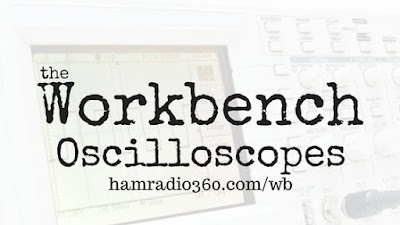
George KJ6VU is a long-time supporter of the SolderSmoke podcast. He has recently teamed up with another ham and launched a podcast called “The Workbench.” This morning I listened to Part I of their interview with the legendary Alan Wolke W2AEW. It was great. As I was listening to Alan I was soldering together a crystal filter for my new receiver, and using my RIGOL ‘scope to check the results.
I liked Alan’s description of how they made images of ‘scope patterns in the days before the advent of Digital Storage Scopes (Polaroid!). I also liked Alan’s scorn for those who use the “Auto” switch on the ‘scopes. The host’s reaction to Alan’s description of a $300,000 Tektronix ‘scope was also fun: “For that price I want to be able to drive a car into it and put a swing set behind it!” Indeed.
Recommended listening:
http://hamradio360.com/index.php/2016/08/30/ham-radio-workbench-5-oscilloscopes-part-1/
Occam’s Bench: M0XPD on the Minimalist Measurement Mindset

Our ace correspondent in Dayton, Bob Crane W8SX, caught up with Paul Darlington M0XPD (above, the guy with the rifle) and interviewed him about his presentation at Four Days in May 2016. You can listen to the interview here by clicking on the link below. I especially liked the comments on the joys of fixing things and the advantages of SIMPLE analog circuitry. Listen to the end and you will learn about Paul Darlington’s connection to the famous Darlington Pair.
http://soldersmoke.com/M0XPDFDIM.mp3
Paul provided more info (including his slide show and presentation notes) on his BRILLIANT Dayton talk here:
https://sites.google.com/site/shacknasties/presentations/fdim-2016
You can buy Paul’s book here:
https://www.amazon.com/getting-there-Paul-Darlington/dp/1523452196
Thanks Paul! Thanks Bob! And thanks to George Dobbs and William of Occam!
Hardcore Homebrew SWR Measurement

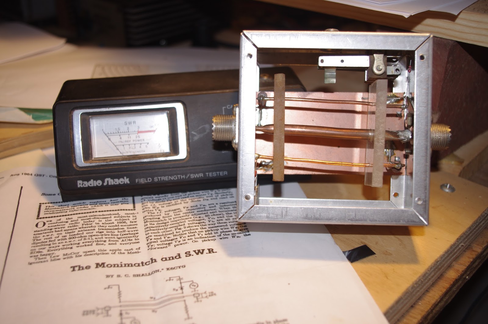
No store-bought, appliance, CB-ish Radio Shack SWR meters for the OM who built the SWR sensor on the right. No! He rolled his own center conductor and pick-up loops. Dennis Klipa and I have been exploring the theory behind SWR meters, so when I saw this thing, I immediately went for it. I picked it up at the Manassas Hamfest. I kick myself for not asking the seller for the story behind this project. If anyone has any ideas on how/why/who built this thing, please let me know. The seller was tailgating close to the stables at Manassas on June 19, 2016.
Possibly the Best Ham Radio Interview Ever: Farhan on “QSO Today”

Stop what you are doing. Run — don’t walk — to the “QSO Today” website of Eric Guth 4Z1UG. There you will find his interview with Ashhar Farhan VU2ESE.
There is so much great information, inspiration and wisdom in this interview. I was so captivated by it that — even with the availability of the pause button — I was unable stop listening even for the time it would take to walk to the kitchen to refill my coffee cup. But at the same time, listening to Farhan describe the joy of bringing a new receiver into operation compelled me to go over to the bench — in mid-podcast — to tweak a receiver that I am working on.
In this podcast you will hear about how Farhan got started in ham radio, about his Elmers about the origins of the BITX, about the Minima and the new HF-1 rig, about Farhan’s spectrum analyzer project and about a new goodwill effort to send BITX circuitry to aspiring hams around the world, especially in developing countries.
Throughout you will hear Farhan speak of the importance of the book, Experimental Methods in RF Design.
I really do think this is the best ham radio interview I have ever heard. Congratulations and thanks to Eric and Farhan.
Here is the link:
Alan Wolke W2AEW Interviewed on QSO Today! And it is GREAT!
A very cool interview indeed. But how could it be otherwise? With Eric on one end of the Skype connection and Alan on the other, coolness was inevitable.
In this interview we are reminded of the FACT that Alan has a major case of THE KNACK. Proof is found in the way he obtained the wire for his first SW antenna: he unwound the magnet wire in the yoke transformer of a discarded TV set. THAT, my friends, is the stuff that KNACK is made of!
Check it out:
I share Alan’s affection for the TEC 465 ‘scope, but I twitched a bit when he said it is “easy to work on.” It scared the hell out of me! It features both plug-in transistors and lethally high voltage — so high that Alan had to lend me a special high voltage probe just to do the measurements.
Alan’s mention of Project Diana and the history of moonbounce reminded me of Ross Bateman, W4AO, the wizard who, in 1952 bounced the first amateur radio signals off the moon. He did it from the town I live in now, Falls Church, Virginia. Alan provided me with the address from which the signals were launched.
Thanks Alan! Thanks Eric!
A VERY Quiet Shack, 4850 Feet Below the Surface
Michael Rainey’s underground shack in Vermont is undeniably cool, but these folks have REALLY gone deep. They are almost a mile down, blocking out that nasty cosmic ray QRN, building sensitive detectors to QSO with some extremely elusive DX: DARK MATTER.
SEE IF YOU CAN SPOT THE TEK ‘SCOPE.
Wonderful video. Thanks to Ira Flatow and Science Friday.
Alan Wolke in the Dinosaur Den (Video)
Very cool. But it makes me sad that my Tek 465 broke (and I can’t fix it!).
Si5351 and the Spectral Purity Mask
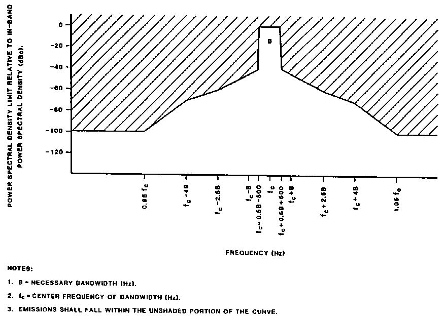
I was thinking about spectral purity standards and the Si5351 chip. I realized that I didn’t even know what the FCC standards for “close in” noise are. The standards for spurious emissions ARE well known, but these are for harmonics and parasitic emissions relatively far from the desired signal. What about unwanted signals CLOSE to the desired signal?
My old 2002 ARRL handbook indicates that the FCC has not established firm standards for this “close in” noise. (They call it “out of band” noise, but are clearly referring to noise that is close to the desired signal but spreading out beyond the desired bandwidth. Phase noise would be in their category.)
In the course of my Googling, I found the above spectral purity mask. I don’t know where it comes from, but I think it is the kind of graph that would be very useful to us as we evaluate the merits and shortcomings of various frequency synthesizers. Would our DDS or PLL rigs fit in this mask? I think an Si5351 rig WOULD. According to KE5FX’s measurements, at a mere 100 Hz from the center frequency, the Si5351 phase noise is already -90 db.
Does anyone have a similar mask showing current standards?
I still don’t understand why so many folks believe that the Si570 is a useful part for homebrew rigs, but the Si5351 is not. Look at the numbers:
Si570
Clifton Labs measuring at 30 MHz carrier. At 10kHz from carrier: -109.6 dbc/Hz
Silicon Labs web site (carrier freq not specified) At 10 kHz from carrier: -116 dbc/Hz
Si5351
KE5FX measuring at 19.99 MHz. At 10kHz from carrier: -127 dbc/Hz
Silicon Labs measuring at 156.2 MHz. At 10 kHz from carrier -112 dbc/Hz.
Can anyone out there explain the technical basis for the belief that the Si570 is a useful part while the Si5351 is not?
It is important to keep things in perspective. ALL of these noise numbers represent VERY small noise levels. Let’s keep is simple and assume a 100 watt carrier signal and a phase noise of -100 dbc/Hz. That means the phase noise per hertz would be .00000001 watts. That’s watts/hertz. How much “noise power” would that represent in a typical SSB passband? Multiply by 2500 Hz and you get 25 microwatts. That’s really low noise levels. Not enough to worry about. And as we’ve noted, we’ve happily used rigs with LC VFOs and crystal oscillators for all these years without every once measuring their phase noise.
Our book: “SolderSmoke — Global Adventures in Wireless Electronics” http://soldersmoke.com/book.htm Our coffee mugs, T-Shirts, bumper stickers: http://www.cafepress.com/SolderSmoke Our Book Store: http://astore.amazon.com/contracross-20
Awesome Kits from Austin Texas
If this is the kind of great stuff that results, then I agree with the bumper sticker:
KEEP AUSTIN WEIRD!
Scroll down to kit #25 for more details on the device pictured above.
Our book: “SolderSmoke — Global Adventures in Wireless Electronics” http://soldersmoke.com/book.htm Our coffee mugs, T-Shirts, bumper stickers: http://www.cafepress.com/SolderSmoke Our Book Store: http://astore.amazon.com/contracross-20
Farhan’s Secret Project: The SPECAN (Extremely Cool) (video)
I had been sworn to secrecy for so long, I thought I was going to burst. I almost hinted at this in the last podcast. But I didn’t. I kept the secret. But now Farhan has made public his latest creation:
http://hfsignals.blogspot.in/p/specan-reboot-of-w7zoi.html
This is really great. I want to build one. I have to build one. I NEED one of these.
Great work Farhan. Thanks for bringing the ham community another amazing piece of gear.
Our book: “SolderSmoke — Global Adventures in Wireless Electronics” http://soldersmoke.com/book.htm Our coffee mugs, T-Shirts, bumper stickers: http://www.cafepress.com/SolderSmoke Our Book Store: http://astore.amazon.com/contracross-20
Unfazed! Fight HISS-teria! Give the Si5351 a Chance.

Thanks to all who have contributed to our discussion of phase noise and the Si5351 chip. Let me throw out some ideas — some technical, others philosophical.
1) We may be worrying about this too much. In all of the homebrew or kit rigs we’ve built over the years, I never recall much concern about the phase noise specs of the LC or crystal oscillator circuit that we were using. What were the phase noise stats on a Heath VF-1? How about the phase noise stats for the little Hartley oscillator in those DC receivers we made? No one even checked. Our rigs usually worked just fine. We would have noticed if they were extremely noisy, but if they were good enough, we left well enough alone. It doesn’t really make much sense for us to now be suddenly very concerned about the phase noise stats of the various DDS and PLL chips that are replacing those LC and crystal circuits, especially when the measurements show that they are usually in the same range as our old familiar oscillators.
2) The perfect can be the enemy of the good, and the “good enough.” We have a long tradition in ham radio of tolerating less-than-perfect or less-than-optimum parts. Remember, the NE-602 has some shortcomings, but we use it. We use it a lot. The IRF-510 wasn’t even designed to be an RF amplifiers, but we have pressed it into service for our PAs.
3) We should be willing to give a new part a try, and we should be pleased if it proves useful. We should be wary of untested claims re the unsuitability of a component. We have to avoid the “works in practice, but not in theory” situation. If something works well, doesn’t create additional QRM, is inexpensive, and fosters experimentation and homebrewing, we should be happy about being able to use it.
4) All electronic components — not just the Si5351! — produce noise. Resistors produce noise. Look at this:
” We can infer… that if we install phase-quiet oscillators in transmitter and receiver, we ought to be able to tune our receiver to a frequency closely adjacent to a very strong signal from the transmitter without encountering anything like phase-noise hiss. Yet, after an exhaustive phase-noise cleanup at transmitting and receiving sites, we test our communication system only to discover that the transmitter still emits broadband hiss! The culprit is transmitted amplifier noise. Just about every modern transmitter or transceiver consists of a high-gain, linear amplifier strip that amplifies the low-level output of oscillators, mixers and phase-locked loops to hundreds of watts or a few kilowatts. Because amplifier circuitry is not perfectly quiet, the output of the transmitter contains noise (hiss) in addition to the amplified signal. Transmitted along with the desired signal, this hiss can degrade the noise floor of nearby receivers-just as transmitted phase noise can. Where does amplifier noise come from? Thermal noise, for one thing. Electronic components operated at temperatures greater than absolute zero generate random electrical noise. This noise is broadband in nature. Greatly amplified in an audio amplifier-or greatly amplified in a radio transmitter, transmitted as broadband radio noise, received and converted to audio-it sounds like hiss. Random variations in electron flow within active amplifier components (transistors and vacuum tubes) are another source of amplifier noise. Transmitted as broadband radio noise, received and converted to audio, it also sounds like hiss.” Source: http://www.robkalmeijer.nl/techniek/electronica/radiotechniek/hambladen/qst/1988/03/page14/index.html
5) It seems that whenever a new technology or part comes along there will be those who issue dire warnings about how we can’t or shouldn’t use it. When transistors came along, there were those who said that hams shouldn’t homebrew with them because — it was argued — without spectrum analyzers we couldn’t possibly come up with spectrally pure signals.
6) We have to be careful lest this obsession with perfection and extremely high tech standards be used as a rationale for not homebrewing, or (much worse) as an argument against homebrew rigs on the ham bands. There is a bit of this going around. Get on 40 meters with rig that drifts a bit or that is not “on frequency” to within 10 Hz and you will find out what I mean.
7) The Si5351 is a good part for our purposes. It does something new and VERY useful for us: It can put out BOTH our VFO and BFO frequencies. It makes it much easier for us to change bands and-or switch between USB and LSB. Its phase noise figures are fine. LA3PNA (citing measurements by KE5FX) notes: “The phase noise of the Si5351 is around -130dBc/Hz at 10KHz. This is quite decent, If compared to a Hartley or Collpits you would see little or no difference. Some of my measurements of published free running oscilators show phase noise in the -110dBc/Hz range!”
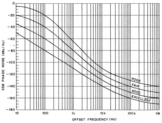
-130 dBc/Hz at 10 kHz puts this part on the “good” curve of this chart. From (http://www.robkalmeijer.nl/techniek/electronica/radiotechniek/hambladen/qst/1988/03/page14/index.html
We should give this little chip a chance! Give it a try!
Our book: “SolderSmoke — Global Adventures in Wireless Electronics” http://soldersmoke.com/book.htm Our coffee mugs, T-Shirts, bumper stickers: http://www.cafepress.com/SolderSmoke Our Book Store: http://astore.amazon.com/contracross-20
Going through a phase (on phase noise)
There seems to be a bit of hysteria on the alleged phase noise problems of the Si5351 chip. The library yields some words of wisdom that help keep things in perspective:
ARRL Handbook (2002) page 14.5: “You would be excused for thinking that phase noise is a recent discovery, but all oscillators have always produced it.”
Experimental Methods in RF Design page 4.12 “At first glance, phase noise sounds like a esoteric detail that probably has little impact on practical communications. This is generally true.” (EMRFD does, however, go on to discuss the problems that arise on both receive and transmit from EXCESSIVE phase noise.)
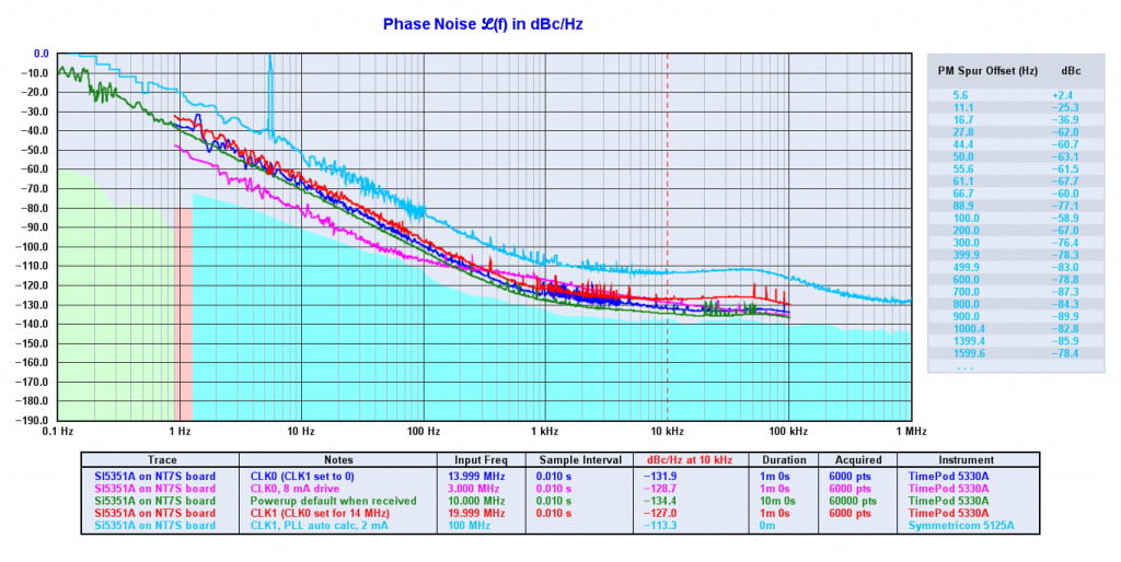
Our old (young!) friend Thomas LA3PNA e-mailed on this subject noting that the Si5351 chip produces less phase noise than many Hartley or Collpits oscillator designs. He provides a link to measurements (far better than mine!) of the noise from the Si5351:
http://nt7s.com/2014/11/si5351a-investigations-part-7/
NT7S puts it this way:
I believe that the plots speak for themselves fairly well. If you compare these results to the receivers in the Sherwood Engineering receiver table, I think you’ll see that the Si5351 acquits itself quite nicely for such an inexpensive part. Personally, I think the Si5351 is eminently usable for many receiver applications, except perhaps the most high-performance. Certainly for the price, it’s going to be extremely hard to beat. I hope this motivates those sitting on the fence to decide if the Si5351 will meet their needs.
Be careful in evaluating statements saying that the Si5351 phase noise is 3-6 db worse than an Si570. This makes it sound like there is a LOT of noise coming out! But again, it is important to keep things in perspective: The noise from one chip might be -156 dbc/Hz while the “worse” chip might be -150 dbc/Hz. That’s still not enough noise to make a lot of noise about.
The ARRL handbook recommended a very simple check for excessive phase noise: Set up a very strong signal in the band of your receiver. Then slowly tune to the signal, listening carefully for any build-up in noise as you approach the signal. I did this, and I didn’t hear any. As for transmit, well, as Pete points out, I think the spectrum police on 40 meters would let us know if our signals were broad or noisy! The ARRL Handbook notes that in a transmitter, “This radiated noise exists in the same proportion to the transmitter power as the phase noise is to the oscillator power…”
Our book: “SolderSmoke — Global Adventures in Wireless Electronics” http://soldersmoke.com/book.htm Our coffee mugs, T-Shirts, bumper stickers: http://www.cafepress.com/SolderSmoke Our Book Store: http://astore.amazon.com/contracross-20
Going through a phase (on phase noise)
There seems to be a bit of hysteria on the alleged phase noise problems of the Si5351 chip. The library yields some words of wisdom that help keep things in perspective:
ARRL Handbook (2002) page 14.5: “You would be excused for thinking that phase noise is a recent discovery, but all oscillators have always produced it.”
Experimental Methods in RF Design page 4.12 “At first glance, phase noise sounds like a esoteric detail that probably has little impact on practical communications. This is generally true.” (EMRFD does, however, go on to discuss the problems that arise on both receive and transmit from EXCESSIVE phase noise.)
Our old (young!) friend Thomas LA3PNA e-mailed on this subject noting that the Si5351 chip produces less phase noise than many Hartley or Collpits oscillator designs. He provides a link to measurements (far better than mine!) of the noise from the Si5351:
http://nt7s.com/2014/11/si5351a-investigations-part-7/
NT7S puts it this way:
I believe that the plots speak for themselves fairly well. If you compare these results to the receivers in the Sherwood Engineering receiver table, I think you’ll see that the Si5351 acquits itself quite nicely for such an inexpensive part. Personally, I think the Si5351 is eminently usable for many receiver applications, except perhaps the most high-performance. Certainly for the price, it’s going to be extremely hard to beat. I hope this motivates those sitting on the fence to decide if the Si5351 will meet their needs.
Be careful in evaluating statements saying that the Si5351 phase noise is 3-6 db worse than an Si570. This makes it sound like there is a LOT of noise coming out! But again, it is important to keep things in perspective: The noise from one chip might be -156 dbc/Hz while the “worse” chip might be -150 dbc/Hz. That’s still not enough noise to make a lot of noise about.
The ARRL handbook recommended a very simple check for excessive phase noise: Set up a very strong signal in the band of your receiver. Then slowly tune to the signal, listening carefully for any build-up in noise as you approach the signal. I did this, and I didn’t hear any. As for transmit, well, as Pete points out, I think the spectrum police on 40 meters would let us know if our signals were broad or noisy! The ARRL Handbook notes that in a transmitter, “This radiated noise exists in the same proportion to the transmitter power as the phase noise is to the oscillator power…”
Our book: “SolderSmoke — Global Adventures in Wireless Electronics” http://soldersmoke.com/book.htm Our coffee mugs, T-Shirts, bumper stickers: http://www.cafepress.com/SolderSmoke Our Book Store: http://astore.amazon.com/contracross-20
Amplifier Woes! Instability at Low Drive Levels! (Video)
I have to keep reminding myself: This is not “plug and play.” These are not appliances.
After I got my 40 meter problems squared away, I was doing some testing on my beloved 17 meter BITX. I noticed something weird: With the CCI EB63A amp feeding my 17 meter Moxon antenna, as I raised the output of the BITX17 driver, at one point (at about half the max input power) the SWR would suddenly spike. Then, as I raised the drive level above that point, the SWR would go back to normal.
I looked at it on the ‘scope. I can see the signal go very ugly at the mid-level drive point. In the FFT display, I can see that there is a strong signal at around 435 kHz. The 18 MHz signal seems to be riding along on top of it. Take a look at the video above.
Additional clues:
I see no signs of the 435 kHz signal at the output of the BITX 17. It seems quite clean.
This problem disappears if I replace the Moxon with a dummy load.
This problem does not show up if I feed the EB63A with my almost identical BITX20. And I use the same LP filter on both 20 and 17 in the CCI amp.
Any suggestions? Has anyone had this kind of problem?
Allison and Pete have been helping me with this. Thanks to both of them.
Our book: “SolderSmoke — Global Adventures in Wireless Electronics” http://soldersmoke.com/book.htm Our coffee mugs, T-Shirts, bumper stickers: http://www.cafepress.com/SolderSmoke Our Book Store: http://astore.amazon.com/contracross-20
Video of Curiously Strong Altoids Tin Frequency Counter
Our book: “SolderSmoke — Global Adventures in Wireless Electronics” http://soldersmoke.com/book.htm Our coffee mugs, T-Shirts, bumper stickers: http://www.cafepress.com/SolderSmoke Our Book Store: http://astore.amazon.com/contracross-20
A “Curiously Strong” Frequency Counter
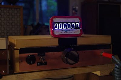
I got a six digit San Jian frequency counter for use with my BITX20. I was trying to figure out how to put it in a box and mount it on the rig when I realized that the counter fits almost perfectly in an Altoids tin. THE RADIO GODS HAVE SPOKEN.
I found the counter on Amazon. I use an eight digit version with my BITX17. But I think the six digit version is better (it fits in an Altoids tin!)
Our book: “SolderSmoke — Global Adventures in Wireless Electronics” http://soldersmoke.com/book.htm Our coffee mugs, T-Shirts, bumper stickers: http://www.cafepress.com/SolderSmoke Our Book Store: http://astore.amazon.com/contracross-20
The Truly Amazing Workbench and Shack of VE7ZWZ (Video)
Brace yourselves. This is almost too much. Prepare for sensory overload and possible palpitations.
Wow. This is really amazing. Note the very casual way Paul manages to mix Eico 430 oscilloscopes with the latest Tek touch-screen ‘scope. Heck, the doesn’t even mention the SP-600s! He does briefly note “a very large transmitter.” Indeed. And he has a microscope on the bench.
This video is part of an excellent YouTube channel called “Mr. Carlson’s Lab.” Great stuff in there. Paul works on everything from old tube type receivers to modern Yaesus and Icoms.
It took me a little digging to find his ham radio call sign. There are many Paul Carlsons on QRZ.com, but Paul’s pronunciation of “solder” gave him away. It seems our Canadian friends also (like the Brits) pronounce the “L.” VE7ZWZ.
Check out his channel. Lots to learn there:
https://www.youtube.com/watch?v=qqmegXoB7lA
Our book: “SolderSmoke — Global Adventures in Wireless Electronics” http://soldersmoke.com/book.htm Our coffee mugs, T-Shirts, bumper stickers: http://www.cafepress.com/SolderSmoke Our Book Store: http://astore.amazon.com/contracross-20