SolderSmoke Podcast #224: Mars. Spurs. Bikes. SDR. NanoVNA. Antuino. MAILBAG


SolderSmoke Podcast #224 is available:

1 August 2020
–The launch of Perseverance Mars probe with Ingenuity helicopter.
–China’s Tian Wen 1 on its way – radio amateur Daniel Estevez EA4GPZ is listening to it!
–Sci Fi Books: Mars Trilogy by Kim Stanley Robinson. No skip on Mars 🙁
–We have some sunspots! SFI now 72 and the Sunspot number is 23.
Bill’s bench:
–Conquering Ceramic Spurs in Q-31 Roofing filter — sort of
–NE602 for a Q-75 converter – Gilbert Cell.
–Measuring low power levels out of NE602. Antuino better than ‘scope .
–NanoVNA Really cool stuff. SDR in there.
–Building a 455 kc LC filter from QF-1 rubble. Using LTSPICE, Elsie…
–Reviving my bicycle AM radio – The “All Japanese 6”
–Understanding L Network impedance matching.
–Bill’s new resistor kit from Mouser. Thanks to Drew N7DA.
SHAMELESS COMMERCE: PATREON, AMAZON SEARCH. THANKS
Pete’s Bench:
–Lockdown Special
–BPF work on SDR Rig
–I U W I H
Mailbag:
VK3HN Summit Prowler 7
VK2EMU “The Stranger”
SM0P HB uBITX in Dubai
AE7KI Worked him in VK from London
ON6UU EA3GCY’s 4020 rig
KA4KXX A Simpler Mighty Mite
W9KKQ M19 DMR
KD4PBJ Radio Schenectady
W3BBO 12AU7 Regen
KE5HPY Another 12AU7 regen
N5VZH Ne602 Converter
KY3R Wall Art
G4WIF Spectrum Analyzer in your pocket
W2AEW Talks to UK Club
KK0S Sent 455 Kc IF cans
KL0S Making 9Mhz filters
VU2ESE Diving into simple SDR schemes
Dean KK4DAS Amateur Radio Astronomy

Alan Wolke W2AEW on IMD, NanoVNA and more (presentation to UK club)

This video is another reminder of how lucky we are to have Alan Wolke W2AEW as a fellow radio amateur, and as a teacher and mentor.

In this video, Alan is talking to the Denby Dale Amateur Radio Society in Yorkshire, UK.

The first part of his talk is about IMD products, the importance of 3rd order products, and the benefits of attenuation.

The second part of the talk (after a few questions) is a look at the NanoVNA, which Alan cites as the “Toy or Tool of the Year.”

I learned a lot from both portions of the presentation. I now find myself wanting an H4 model of the NanoVNA (bigger screen). Or maybe even an F model. Thanks to Alan, I now know what S21 and S11 means.

Thank you Alan, and thanks to the Denby Dale ARS.

73 Bill

An Attenuator from Fred KC5RT

Fred, KC5RT, sent me an electronics “CARE Package” with lots of really useful stuff, including an attenuator with switches. All I had to do was find a box and some connectors. An appropriate box was quickly found in my junk box (TRGHS). So Fred’s attenuator was added to my attenuator arsenal — thanks to Farhan for getting this started.

I’ve already put Fred’s attenuator to good use: Instead of building an RF gain control for my Q-31 receiver, I just put the attenuator between the antenna and the receiver.

Thanks Fred!

Feedback on Farhan’s FB Feedback Amp Video


As I said a couple of days ago, Farhan has put out a very informative video on amplifier design. During the video we can see him determine bias, feedback and load levels, then select component values. We then see him actually build the amplifier “ugly style” and use his Antuino to test it. Fantastic.

Watch Farhan’s video here: https://www.vu2ese.com/index.php/2020/06/18/feedback-amplifier/


I sent Farhan some of my reactions to the video. In the hope of stimulating some discussion, I repeat them here:

___________________

Wow Farhan, I really enjoyed your video and learned a lot. You definitely have the Knack for explaining this stuff.


I have been struggling to understand feedback amps for a long time. I took up this topic on pages 187-190 of the “SolderSmoke — Global Adventures” book. I was more focused on the benefits of FB amps, and on how and why feedback affected input impedance.

I took notes as I watched:

— I liked the fulcrum analogy.

— Really wonderful how you describe the selection of components to get desired bias.

— Even better when you explain tapping down of RF coil to get 50 ohms to look like 200 ohms. Great stuff.

— Standardized on BNC. FB!

— .1uF caps. Love them! No argument here!
— I copied your resistor list. Will use it with Mouser.

— Saving the pigtails. Indeed!
— I like your ugly “resistors first” technique. I may have to move away from Manhattan.

— Wow. Ugly circuits IN SPAAAAACE! FB!
— 2N3904 I always think it is EBC when looking at the flat end of transistor with leads facing down. Only had reverse pinout with PN2N2222. EBC is my usual assumption.
— I still have the big box of trifilars you left me. I use them. Thanks!

— I like that VTVM in your Antuino. Very handy. Want one! Also, We need to get the Antuino to go down to below 455 kHz.

— I also like your dual Return Loss and SWR display. I think in terms of SWR. Return Loss sometimes messes me up.

— Didn’t know about the Hold and Zoom feature on Antuino. FB.
— Your measurement of the Q of the crystal was awesome.
— I checked my soldering iron temp: I’m at 480 C A bit too hot. Will back off.
— Good description of need for an attenuator at amp output to keep it in Antuino’s range.
— As I watched you tug on the components after the solder cooled, I remember an old and silly admonishment from the ARRL Handbook: NEVER use solder for mechanical connections. Ha! They were WRONG!
— Demonstration of the flatness of feedback was great.
— I found your measurement of impedance using the SWR feature of the Antuino to be very useful. Is there a chart relating the SWR/Return Loss to actual impedance values?

— Loved your description of how output impedance affects input impedance. That is why you advised use of TIA amps in my DIGI-TIA. But now I’m thinking that if I can accurately measure impedances of non-TIA amps, I can design L networks that will keep the crystal filter passbands ripple-free, right?

— Great explanation of the benefits of the 6 db pads at amp output. Allison often recommends this. Now I know why.

— Wow! Now I KNOW what that two-tone box you left with me is for! Now I understand how it can be used to measure IMD on FB amps. I pulled mine out just as you began to discuss yours. Really cool.

Thanks a lot Farhan for doing this. These videos will be of long-lasting use to homebrewers around the world. I hope we will see many more VU2ESE videos like this one.

73 Bill

Software for Computer Interface with NanoVNA: NanoVNASaver

In the UK, “brilliant” is high praise indeed. So when Tony G4WIF told me that the NanoVNASaver software was brilliant, I took heed.

Being able to use the tiny (nano!) device with your computer makes it a much more accessible and useful tool, especially for those of us with fat-finger syndrome.

The photo above shows the NanoVNA measuring Return Loss and SWR on my 40 meter dipole. You can see the identical Smith Chart traces on the two screens.

Download and installation was very easy. I got my Windows PC version from here:

Other versions available from here:

Coincidently, a fellow just today put out a video on how to use this software with the NanoVNA.

Thanks Tony!

Alan Wolke W2AEW Explains the Vector Network Analyzer (VNA) (Video)

I told Alan that his video on VNAs was — for me — very timely. The video popped up on YouTube on the day than my NanoVNA was being delivered. TRGHS.

Alan does a great job in explaining what the VNA does. Particularly useful for me was his explanation of the VNA’s ability to measure phase differences (through the use of directional couplers).

I am having fun with my NanoVNA, happily measuring SWR and the bandpass characteristics of various filters. Mine came with what looks like a guitar pick — this is used as a stylus to hit the small boxes on the touch-screen. A nice touch…

I wish there was some good software for use with this VNA. Apparently the nice software described by Joe Smith (yesterday’s blog post) is quite expensive. Is there a free alternative out there?

NanoVNA, Millen Dip Meter, Kilo-Megacycles, and Measuring the Speed of Light (Video)

Yesterday my NanoVNA arrived. This morning I was looking for info on how to use it and I found this really wonderful video from Joe Smith.

Wow. Joe gives a really useful intro to the capabilities of this amazing little device. He even reaches back in time and compares NanoVNA results with those obtained by a Millen Grid Dip Meter. He pulls out of his junk box an attenuator that is so old that it is marked in “Kilo-Megacycles.” (Shouldn’t we revive terms like that?)

Joe also gives us a taste of what it is like to live and work in the GHz range. He warns us never to touch the SMA connectors on our NanoVNAs (too late Joe). And — get this — he uses a torque wrench to connect the little SMA coax connectors to the NanoVNA. I’m not kidding. A torque wrench. Joe connects surface mount capacitors and inductors that have their values specified not only in picofarads and microhenries, but also at the specific frequency at which they were measured.

My understanding of the Smith Chart was greatly improved by watching Joe’s video.

Icing on the cake: Joe wraps up the video by using the NanoVNA to MEASURE THE SPEED OF LIGHT. Great stuff. Thanks Joe.

Here is Joe Smith’s YouTube channel:
https://www.youtube.com/channel/UCsK99WXk9VhcghnAauTBsbg

Now I have to get the software to use the NanoVNA with my computer.

Video on the Galaxy V VFO Project

This is the second version of this video. I had some technical difficulties getting it to upload in High Definition, but I was able to work it out in this version.

In this video I describe the VFO project, talk about how I made use of the e-bay Galaxy V parts, talk about the circuit (series-tuned Colpitts), conduct some stability tests, and discuss many of the ways a VFO like this one can be useful to the radio amateur.

Thanks to Pete Juliano for inspiring this effort.


Blog — “Chinese Electronics Products Tested”

I was looking for information on my FeelTech FY3200s Signal Generator. I came across a very informative blog; it covers a variety of other Chinese gear and parts.

Here is the Feeltech FY3200S article:

https://chinese-electronics-products-tested.blogspot.com/p/fy3200s-function-generator-tested.html

Here is the home page of the blog:

https://chinese-electronics-products-tested.blogspot.com/

And here is backround information on the author:


Thanks Jos!

How to Measure Output Impedance (video)

Thanks to Tony Fishpool G4WIF for alerting us to this very useful video by Alan Wolke W2AEW.

Alan’s video channel is a real treasure-trove for homebrewers.

It was very cool to see “AEW” inscribed on the function generator that Alan built 30 years ago.

Be sure to stay to the end of this video for some electronics humor from Alan. (Steve Silverman: Take note — we might want to add this to the lexicon.)

Now I’m going to search Alan’s YouTube channel for a video on how to measure input impedance.

Antuino Filter Analysis

Farhan had given me one of the early Dayton Hamvention models of the Antuino SWR/PWR/SNA RF test lab. He later identified the need for a few mods to improve performance on that early model. So I brushed up on my surface mount soldering, got the needed (tiny!) parts and made the mods. I also put the battery pack inside the box and put some feet on the Antuino cabinet (it just seemed like the right thing to do).

Antuino has already proven to be very useful as an SWR analyzer. I know have a much better understanding of the SWR bandwidth of my wire antennas.

And it is very useful in evaluating the passbands of filters. I had an old 11.273 MHz filter from an old CB radio in my junk box. I have no specs on this device — I didn’t know what impedances it was designed for. So it was time for some Antuino technical detective work.

First, take a look at the filter with nothing between it and the Antuino. Input and output on the Antuino are 50 ohms, so here is what the passband looked like with 50 ohms:

Next I put in two 47 ohm resistors, one in series with the input, the other in series with the output. Antuino connected at the other side of each resistor. Here is what it looked like. Note the improvement in skirt shape. But there is still a lot of ripple in the passband:
Then I went to 100 ohms. The passband ripple was reduced noticeably:
Then up to 330 ohms. Here the passband doesn’t seem quite as flat as it was with 100 ohms:
Finally, 1000 ohms. Definitely too much. Note the ripple.

Farhan prefers the passband with the 100 ohm resistors. I agree.

BTW the filter is from TEW of Tokyo, Japan. Model FEC-113-2 11.2735 MHz No. 2 A 2
It had three crystals on the board with it: 11.275 and 11.272 — these are obviously for LSB and USB. The third crystal is at 11.730 MHz, indicating to me that they had a second IF of 455 kHz in this rig. If I use it, I think I’d stay with single conversion. At 11.273 MHz the filter is of ideal passband width for SSB. I do feel the urge to build something around this filter.

Doing the mods on the Antuino was fun, and having worked on the device at least a little bit I feel more of a connection to it.

Farhan Visits Northern Virginia and SolderSmoke HQ

Our good friend Farhan came to Northern Virginia last week for the 50th Anniversary Symposium of AMSAT. We were really delighted that he also came to SolderSmoke HQ. Elisa and I gave him a lightning tour of Washington DC (including a quick visit to The Air and Space museum) and then we headed back to the shack from some radio work.
In the picture above you can see my BITX-20 (that Farhan designed) off his right shoulder. Off his left shoulder you sits my ET-2 rig. I really wanted to show Farhan how well the N0WVA regen performs — he was impressed, especially when we started listening to SSB contacts. It was really amazing that we were doing this with just one J-310 FET. This was great fun. Farhan tells me that he will soon take up the “two transistor challenge.”
When he was here in 2017, I tried to demonstrate my version of Rick Campbell’s R2 Direct Conversion receiver. Unfortunately, when I tried to show off the “single signal” capability that is the whole purpose for this receiver, it was NOT producing a single signal output — you could hear the signal on both sides of zero beat. One of the small AF chokes I had used had gone open, knocking our one of the two DC receivers. This time I had the problem fixed and single signal reception was successfully demonstrated.
Farhan brought me two pieces of test gear that I have needed for a long time: A step attenuator and a two tone generator. Paired with his Antuino, these devices will bring about a big increase in capability on my bench.
It was really great to have Farhan in the shack. We had a great time talking about ham radio and homebrewing. Elisa and I both really enjoyed hearing from Farhan about his travels and about his life in India. We are all really lucky to be in the same hobby as Ashhar Farhan. Thanks for the visit Farhan.
Here is a quick video of Farhan tuning the BITX 20.

Antuino Mods and Updates from Farhan

Both messages from the BITX20.io email group.

26 July 2019

Peeps:

The Antuino has been in use for over a few months now. We had produced 100 of them that were sold at the FDIM. These work quite well for an SWR meter and Antenna Analyzer, but they were sub-optimal for serious RF work. For those who bought it for SWR measurements, you can continue to use it. For those who want to improve it, read on.

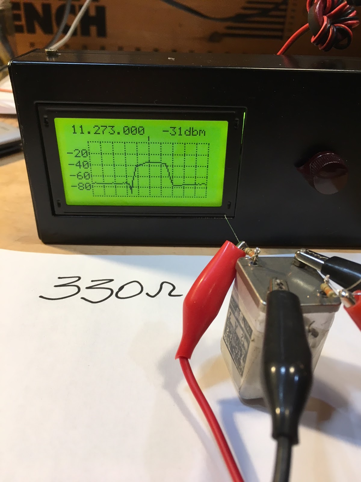
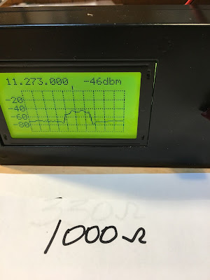
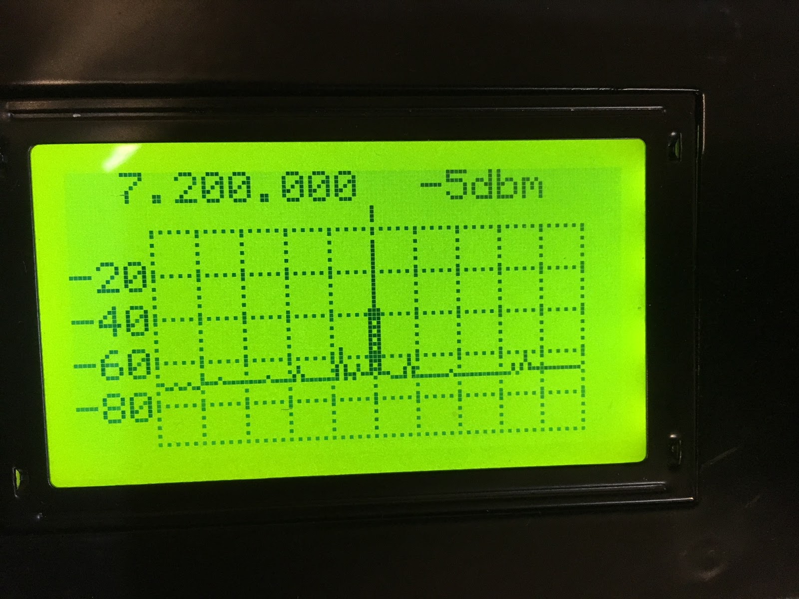
It was noticed that the db scale was not accurate. Antuino was designed to be an accurate and precise instrument. The db readings should be within +/- 1 db accuracy. However, they tended to vary by as much as 2 db on the upper range of power measurments. This was finally tracked down to having too much gain. I had prototyped the original with 2N3904 transistors but in production we used BFR93W as I guessed it would have ‘better’ performance. It turned to be a bad choice. The higher gain resulted in compression of signals above -30 dbm. This restricted the useful range of the Antuino to about 50 db.

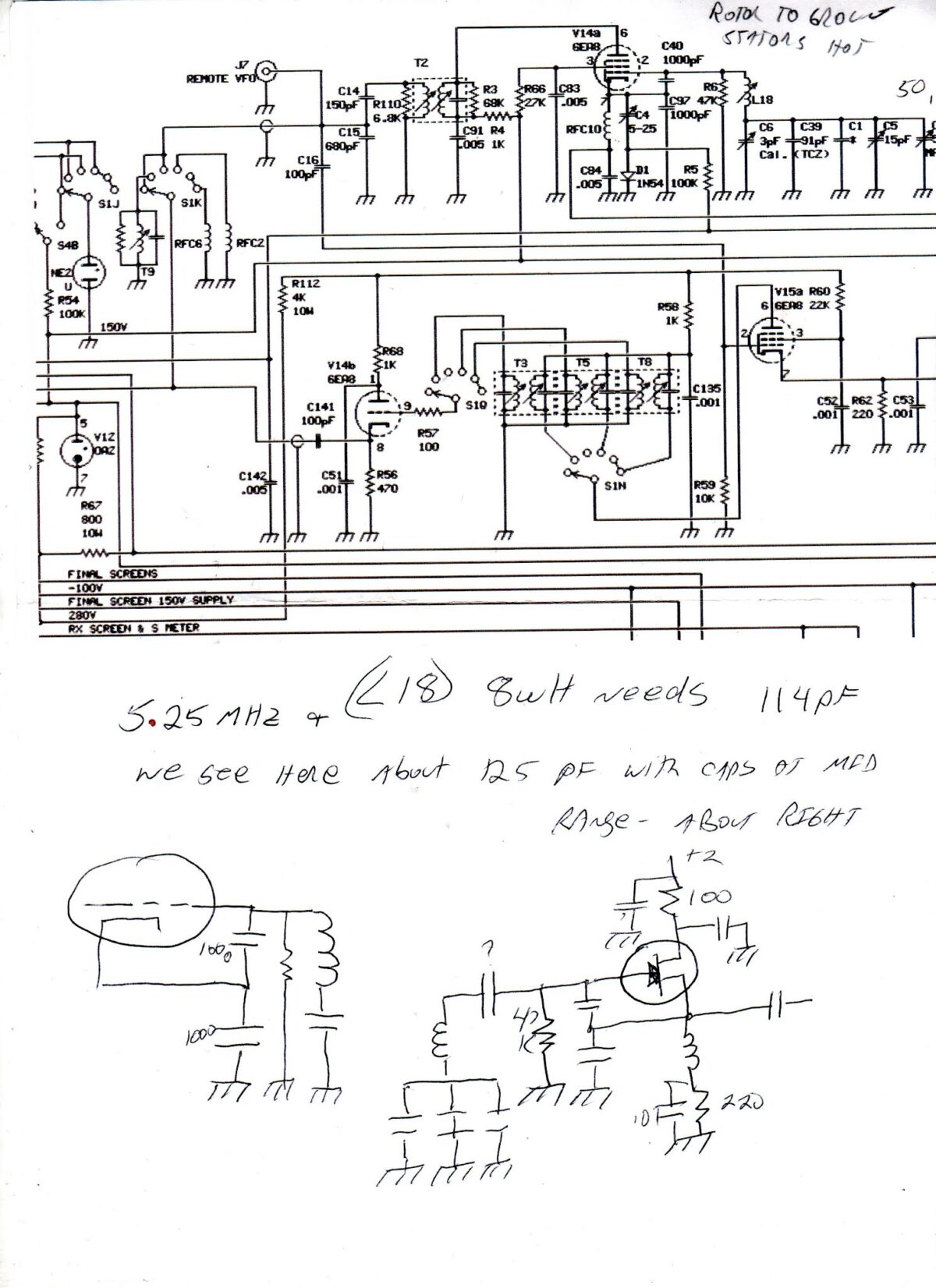
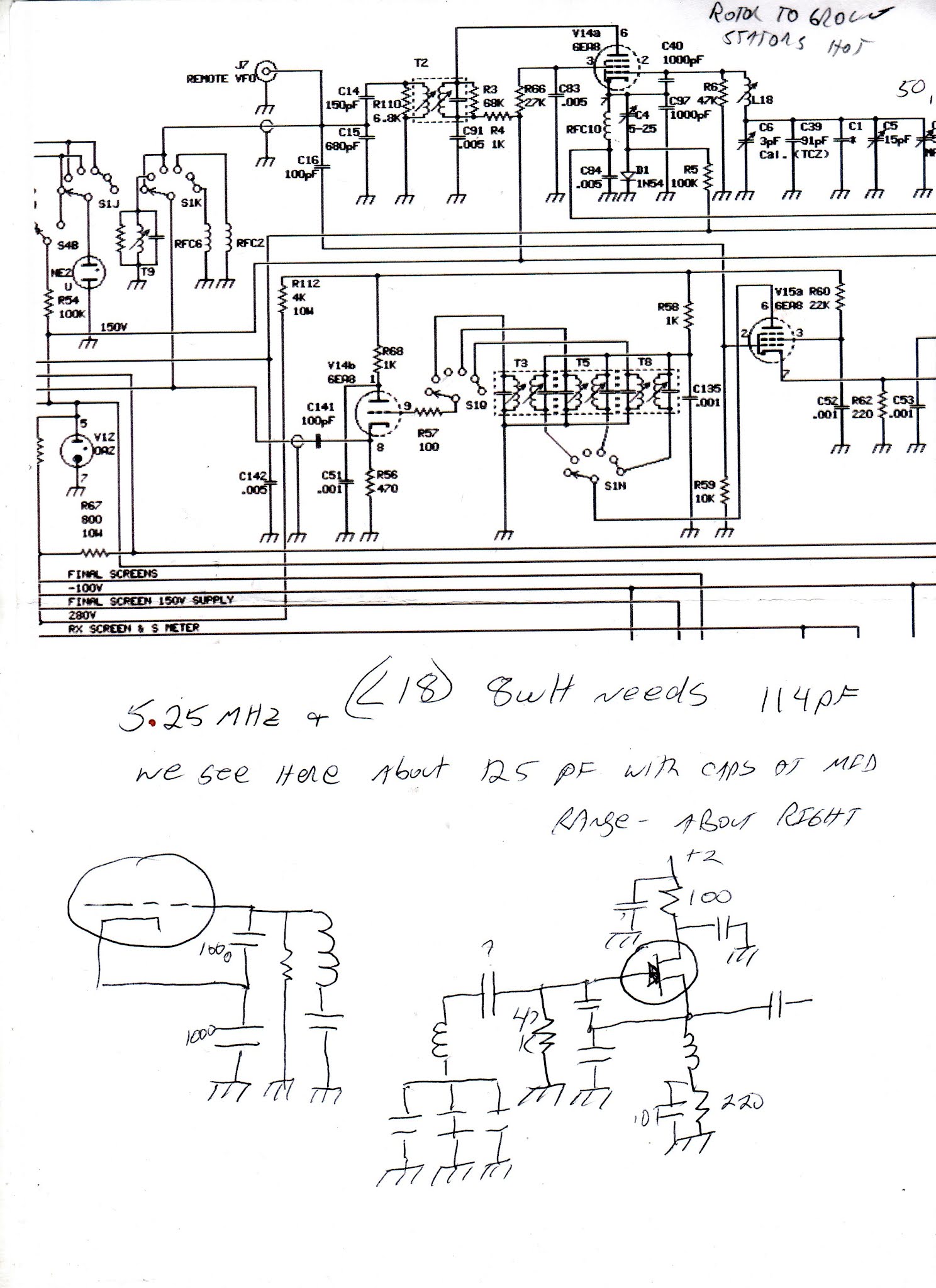
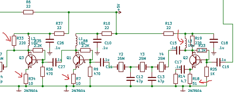
I am attaching the new (Version 2.1, it is a minor edit of the V2 that was sold at the FDIM). In summary, these are the changes:
1. The new software with a cleaner way to calibrate is on https://github.com/afarhan/antuinov2.1. Please upgrade to it even if you don’t want to carry out the other hardware modifications.
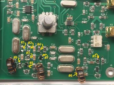
2. Replace the Q1 and Q3 transistors to 2N3904. Although the PCB pads are SMT, you can solder the leaded type by twisting the legs around.
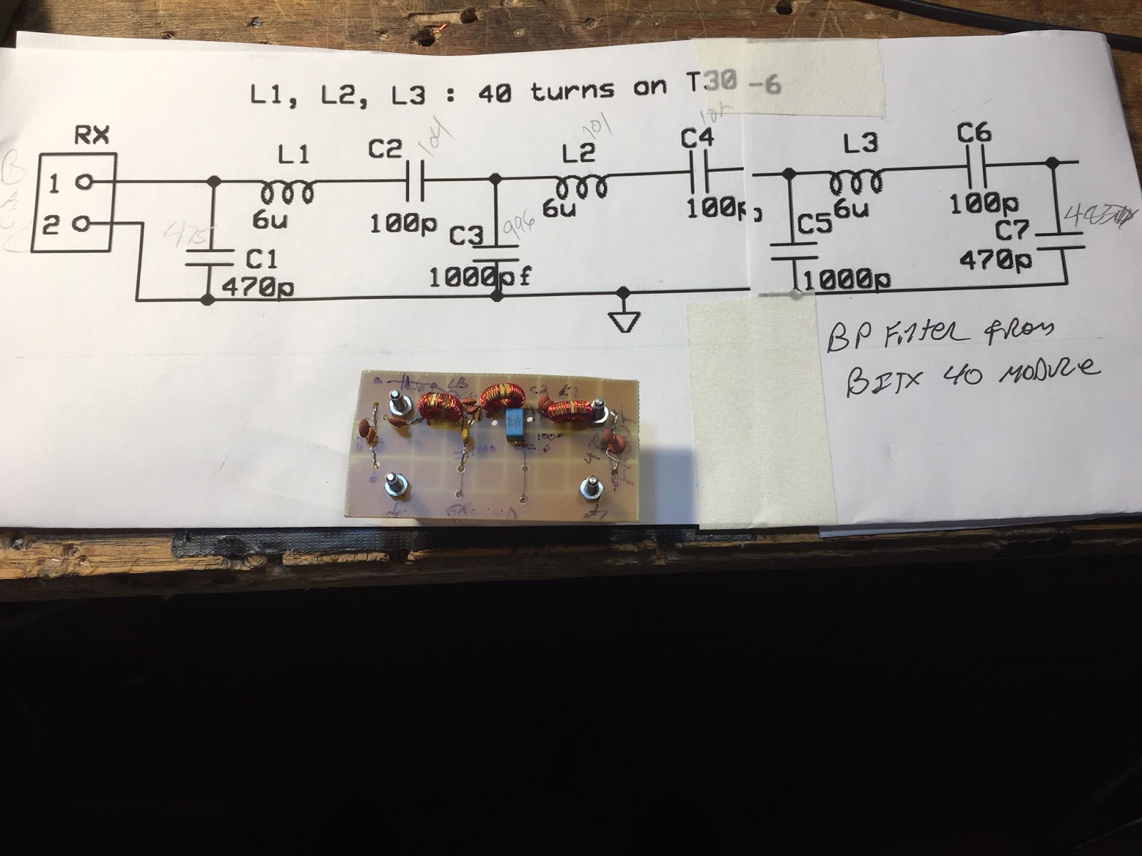
3. In the first IF amplifier (that immediately follows the mixer), we decrease the emitter resistor (R18) from 100 ohms to 51 ohms (you can also parallel a regular 1/4 watt 100 ohms with the original 100 ohms to get to 51 ohms). We also parallel the (R19) 220 ohms collector load with a 10 uh inductor (you can use 10 turns on FT 37-43), the exact value is not important.
4. In the second and third IF amplifiers, we replace the 100 ohms emitter resistors (R7, R34) with 10 ohms and remove the 4.7 ohm resistors (R32, R4).
5. In the last IF amplifier, we change the load resistor(R33) from 51 ohms to 220 ohms.

You need a few 10 ohms resistors and a 220 ohm resistor. You can resuse the R31 at R18.


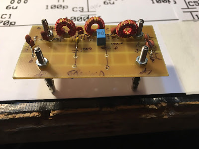
Attached are the images and the circuit.

73, f
_._,_._,_


August 3, 2019

Every instrument has limits on its accuracy. While making the Antuino, I was well aware of its deficiencies.

I made a decision to keep it simple to a point where a radio ham could throw this thing together in an evening or two.

In order to overcome the limitations inherent in the Antuino design, the complexity could have been prohibitively complicated and expensive.
On the other hand, it is an extremely useful instrument that grows on you. I no longer use a frequency counter or the specan. I rarely use the oscilloscope. Antuino does most of my measurements.

There are two very important things you must be aware of while using the Antuino :
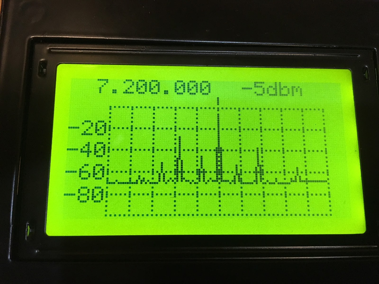
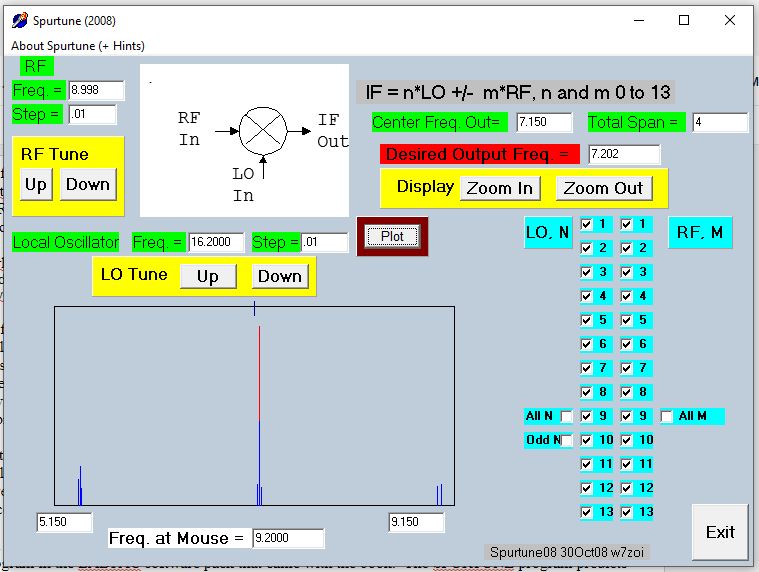
1. In the power measurement mode (the problem is non existent on swr or sweep mode), any reading above 25 mhz could be an image. Thus, if you see something at 35 mhz, you will have to do some mental math to figure out if it is not an image. An easy way to know is to add an external low pass filter with 25 mhz cutoff.
You have to use it like a radio in this mode. If you want to measure the harmonics from your pixie radio with 7040 crystal, tune to 14080, 21120, 28160 and measure. It is as accurate as any spectrum analyzer with more than 80 db of usable bandwidth. Raj and I struggled to get this for a month.
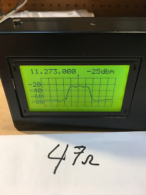
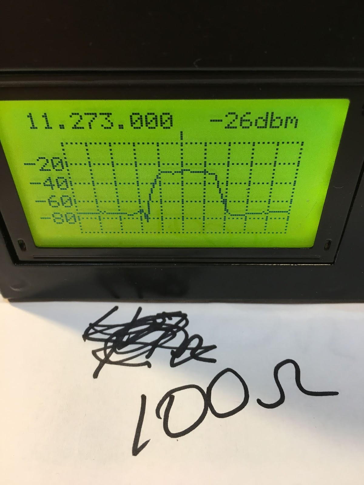
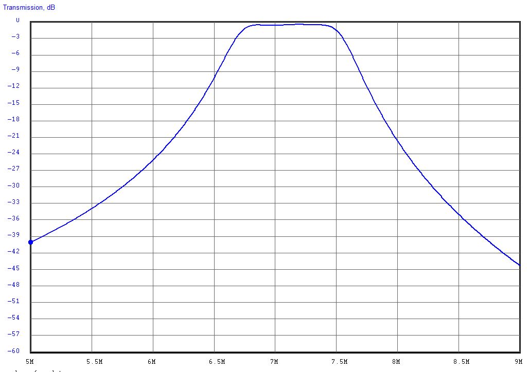
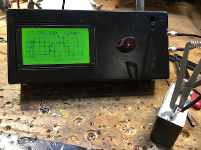
2. Unlike a full fledged spectrum analyzer, Antuino has just one bandwidth of about 7 KHz. This is enough to made IMD measurements at 20 KHz tone separation. The sweep plot does only 128 readings. Thus, if you sweep a low pass filter from 0 to 20 mhz, it will measure the filter response every 120 khz. If there is something lurking between the steps, it will miss it. This is a common challenge with spectrum analyzers. So, a crystal filter should be swept at less than 100 khz.
There is a software hack to mitigate this. First : introduce another control for step size. This can slow down the plot. A 30 Mhz sweep at 5 khz steps will involve 30 x 200 =60000 readings.It could take minutes. The Second : write a more optimal Si5351 routine that changes frequencies faster. I know that smaller jumps can be instantaneous on Si5351. I don’t know that hack. If someone wants to take a stab at it, I am willing to work with them.

In a nutshell, Antuino is a very useful instrument. You don’t have to buy it. You can build it. It is just as challenging as a direct conversion receiver. It does a fabulous job though. It can measure oscillator frequencies, it can measure amplifier gain, distortion, frequency response, it can measure filter response, it can show mixer behaviour, it can tune your antenna, it can measure power from a few uV to 100 mv and more with attenuators. It does all this slowly but surely. Like any precision tool, you must know its limitations and use them as an aware user. I would wager that if you have to choose just instrument for your lab, it would be this; Apart from a DVM.
And (I repeat) don’t buy it, build it (grin)

– f

Antuino’s Cubesat Origins, and How it Works (with video)

In a series of e-mails to the BITX20.io group, Ashhar Farhan VU2ESE provided background information on the origins of his new “RF Lab in a Box’ — the Antuino. He also explained how the device performs the SWR meter, Power Meter and Scalar Network Analyzer functions.

Farhan’s Antuino Page: http://www.hfsignals.com/index.php/antuino/

Dec 27, 2018 to BITX.io

peeps,


while trying to measure the swr on the cubesats, i figured i couldnt use any of the analyzers i had access to. they were simply too big to be stuffed inside a 10 cm cube. my simple resistive bridge was too insensitive for any reasonable work. so, i sat down and made an antenna analyzer from a spare raduino.

the code is wobbly and just about enough to get my work done. it works on a superhet principle. this is not my clever idea, rahul had mentioned this approach taken by a russian builder. i havent seen the original design. it would be interesting if rahul or someone can point me in the right direction.

the code and a pdf of the circuit is on https://github.com/afarhan/antuino. i am attaching the circuit for the lazy bones.

have a great holiday and get some dx !!

– f

Dec 28 2018

Jerry,

first, thanks. there is substantially your code in there.

second, onto the circuit. it uses two clocks. not three. the third is a spare output. more on that later.

the circuit here uses a resistive return loss bridge. the clock 1 drives the bridge through the R22 to a low level of -10dbm. If the bridge is perfectly balanced (that is, the antenna, R21, R29, R16, all the four are the same ohms), then, there will be no RF developed across pins 3 and 4 of the ADE mixer. Under ideal match conditions, there is no RF across the R26. As the mismatch increases, so does the RF across R26.

We could directly detect the voltage across the R26 with a diode detector. This is quite a popular configuration with most of the simple resistive kind of SWR bridges (like the one designed by Dan Tayloe). This simplicity comes at a cost. The problem is that the detector responds to all the RF between the arms. For instance, if another ham down the block starts to transmit, that energy will show up across the R26 and you will get crazy SWR. I had that problem with broadcast FM showing up on my 7 MHz dipole! Even if there was no RFI from elsewhere, harmonics and spurs from your own transmission can show false readings.

Here is an example: a 7 MHz transmitter with a 14 Mhz harmonic that is 20 db down is connected to a 7 MHz dipole. The dipole is perfectly tuned to show 1:1 SWR, hence, it should show no RF across R26. However, as the antenna is reflecting back the 14 MHz energy, the 14 MHz shows up across the R26.

What’s the solution to get a clean dip?The solution is to substitute a simple detector like a diode detector with a simple receiver that is tuned exactly to the frequency that you want to measure the antenna at.

So, the ADE-1 mixer, Q2, Q1 together form a very simple superhet receiver with 25 MHz IF andCLK2 as the local oscillator. The RF at the IF is directly detected and converted to db range with the AD8307. This simple configuration makes this a very powerful instrument.

Here are things you can do with it:

1. Switch off the CLK1, now you have a receiver that can very accurately measure RF levels at any specific frequency in db range. For instance, you connected your transmitter with a suitable RF attenuator to P3, you can tune to various harmonics and measure them very accurately. If you inject a two tone signal into an amplifier, you could easily measure the IMD and IIP3.
2. With the CLK1 on, the instrument now measures the return loss. you can measure the SWR of an antenna, S11 parameters of an amplifier, filter, etc.
3. With CLK1 off, CLK 2 on, the CLK2 can now tune to the frequency tuned in by the receiver’s LO (CLK0). By connecting a device/filter between P3 and P4, you can sweep it to measure the gain, frequency reponse.
4. As the diode mixer (ADE-1) has harmonic response, a local oscillator at 135 MHz, will also convert a 430 MHz signal into 25 MHz IF (430 – (135 x 3)). This is possible because we are driving the diode mixer with a square wave from the Si5351 and the local oscillator at 135 MHz also has a 405 Mhz harmonic in it. Hence, the range of this instrument extends to UHF.

The ADE-1 mixer is quite similar to the ubitx mixers. You could even use ubitx kind of discrete version of a diode mixer, it doesn’t work too well beyond 50 MHz. The pins 4 and 3 of the ADE-1 are the primary winding of the RF-input side transformer. The documentation recommends that we must ground 4, but that is not essential. We need a differential drive between those two pins, that is what the bridge provides anyway.

73, f

jerry,

i built it so i could stuff it inside the cubesat to measure the antenna. an external spectrum analyzer and its cables were upsetting the RF model hence, i needed something that could read the return loss sitting inside the cubesat. then, i borrowed by daughter’s DSLR with a monsterous tele lens and sat 100 meters away to read the the LCD display as it swept through the range.
the analyzer was removed once we knew the correct dimensions and the actual payload went inside the bird.
– f

SolderSmoke Podcast #212 HDR, Boatanchors, SDR, Antuinos, Spurs, QSX, Mailbag

Dale Parfitt W4OP’s SBE-33 with modern digi freq counter

SolderSmoke Podcast #212 is available:

http://soldersmoke.com/soldersmoke212.mp3

22 June 2019

CONGRATULATIONS TO PETE: Licensed 60 years today

Pete Juliano during Field Day, 1959

Sideband Engineers Models 33 and 34 — Thanks Pete!
Hans’s QSX SDR Rig at Dayton-Xenia and FDIM
W8SX FDIM interviews

Pete’s SDR Projects — Update

The Peregrino SSB transceiver in the summer SPRAT

Why no rare earth cell phone speakers in ham projects?

My HDR “waterfall” project

Farhan’s Antuino
Cubesat origins
RF Lab in an box
SWR, PWR, SNA
Superhet receiver with ADE-1 at front, and log IC at the output
Adapters (SMA to BNC) help
DON’T BLOW UP THE INPUT RESISTORS (LIKE I DID!)
My dirty DIGITIA — Denial, then acceptance
FFT
Useful programs: SPURTUNE and ELSIE
A better bandpass filter for the DIGITIA
The importance of a good test set up with Antuino

Manassas Hamfest: WA1UQO, W4WIN, AI4OT

MAILBAG:
KG7SSB
WA3EIB
VK4PG
W3BBO
Jeff Tucker — Who owns Drake 2-B #4215?
KN4BXI
KC5RT
K3ASW

Face the TRUTH! LOOK at Your Signal with an Antuino!

At first, I didn’t want to believe it. I was in denial. I wanted to shoot the messenger (in this case, the Antuino). How could my beloved HB 40 meter DIGITIA transciever have an output that was so…. so DIRTY! Everyone tells me it sounds great. But the little Antuino screen told a different story. Strong spurs up at 9 MHz and down at around 5.4. And lots of places in between. (In these display images, the center frequency is 7.2 MHz and each division to the left or right is 1 MHz.)

Farhan tried to get me to face the truth: “The frequency domain viewing of RF Signals is the opening of the third eye. Once you start seeing signals as a bunch of simultaneous sines, you will always be wary of the waveforms on the scope. In fact, time domain readings make little sense.”

At first I blamed strong VHF RFI and my somewhat hay-wire test set up. My homebrew Rube Goldberg 20 db attenuator was probably picking up some of the VHF RF. But as I looked more closely at the output of the transceiver in the frequency domain, I gradually accepted that it was true. There were a lot of spurs. I have a general coverage receiver in the shack, and with it I could hear the little devils. And after some adjustment I could see them in the FFT display on my Rigol o’scope. An exorcism was definitely needed.

But first came a tightening up of the test setup. Pete advised me to do this. I had in the shack some really nice dummy load/attenuators from the HP8640B Signal Generator that Steve Silverman had given me (and that Dave Bamford had hauled across New York City for me). I ordered the necessary N connectors and adapters and soon my test setup improved a lot.


All this got me thinking about spurs. I consulted EMRFD and was reminded of a really great program in the LADPAC software pack that came with the book. The SPURTUNE program predicts spurs and tells you what to look out for. It is really illuminating. Try SPURTUNE.

Through this, I gained a better appreciation of the importance of the bandpass filter in an SSB transceiver. I’d always thought of it as something that allowed the other mixing product to be eliminated while passing the one you want. But I came to realize that it does a lot more than that — it also helps get rid of spurs. If it is designed right. Mine was not. I had plucked it out of an old QST article and had not paid much attention to it. All it needed to do was knock down the unwanted mixing product, right? And in my transceiver (9 MHz IF, VFO running 16.0 – 16.3) MHz that unwanted product would be way up at 25 MHz. It wouldn’t take a lot of selectivity to knock that down. But I’d forgotten about the closer-in spurs. Antuino reminded me of them. And SPURTUNE explained where they came from.

For the exorcism, I decided to use the bandpass filter design from Farhan’s BITX-40 Module. I had made the BP filter on this rig “plug-in” so it was easy to build a new filter.


I even checked out the filter design in a simulator. For this I use ELSIE. Another very useful program. Here is what ELSIE predicted for Farhan’s BITX40 Module filter:

I plugged the new filter into the DIGITIA and… SUCCESS! The big spurs that were bothering me were gone and the remaining spurs were all below 50db down from the main signal. Here is what it looks like now:


The Antuino is a very useful device. You can learn a lot from it, but you have to realize that this is not plug and play radio. You have to think about what you are testing, make sure you have the test gear set up properly, think about the circuit you are looking at, and be careful not to put too much RF into the device.

Three cheers for Farhan and his new Antuino! More on this soon. And we will talk about this on the next podcast.


First Use of Farhan’s Antuino Scalar Network Analyzer

I was learning my way around Farhan’s new Antuino this morning. Very cool. I decided to start with the Scalar Network Analyzer. I’ve spent so much time measuring and plotting filter response curves BY HAND… the Antuino is an opportunity for me to move into the 21st Century.

In the picture you see the results. I was using a Heathkit SSB filter with the center frequency at 3.395 Mhz. The Antuino was set for that freq, with the screen range set at +/- 10. That means each division on the screen is 1 khz (right?). The Heath filter is advertised as being 2.1 khz wide at 6 db down. That pretty much matches what we see here.

You can see ripple in the filter passband. This is almost certainly the result of an impedance missmatch. It looks to me like the Antuino is set up with 50 ohm inputs and outputs. The Heath filter probably needs higher impedances to have a smooth passband. I will try later to set it up for a smooth passband.

It is easy to see how useful this device will be. Thanks Farhan!

More on the Antuino here:

FDIM Interview with Farhan VU2ESE

I didn’t realize that our correspondent in Dayton/Xenia had interviewed Farhan. There was a typo in the audio file name and I was wondering who this UV2ESE guy was. A Ukrainian QRPer? I was really pleased to find out that it was Farhan.

In Bob’s interview you will hear Farhan discuss the capabilities of his new Antuino (pictured above). Pete’s Antuino is in the mail, going transcontinental. It should arrive in the Newbury Park Laboratory later this week.

As for the spectrum analyzer that Farhan got me last year, I am waiting for retirement (soon!) to get that one going. But there is a danger that the Antuino will leave little room for the older tech…

In the interview you will hear Farhan talk about the Antuino circuitry, and about the roots of the three main devices in the Antuino box. Very cool.

Thanks again Farhan. And thanks Bob.

Here is the interview:

http://soldersmoke.com/VU2ESE FDIM 2019.m4a


Farhan’s Antuino page:

http://www.hfsignals.com/index.php/antuino/

Antuino: Farhan’s Compact RF Lab In-a-Box

I now have Farhan’s latest invention, the Antuino. Pete will have his shortly. Very cool. SWR meter and antenna analyzer, power meter and scalar network analyzer all in one box. I put an old-school knob on the rotary encoder — it seemed like the right thing to do. Soon I will be able to find out if my rigs have spurs or are somehow non-compliant. I’m sure Farhan’s “RF Lab in a box” will be an important addition to my test gear arsenal. We will be talking about this in upcoming podcast episodes.

Mike N2HTT did a nice write up of the new device:

https://n2htt.radio/2019/05/26/hello-antuino/

And here is the info from the htsigs.com page:

http://www.hfsignals.com/index.php/antuino/

Thanks Farhan!