
I love all the “DO NOT ATTEMPT” warnings. Wow, even HP got so skittish about this stuff. Marc has a great sense of humor and notes that, “no cavity resonators were harmed in the production of this video.” I like the description of the mixers and the photo of the mixer antennas.
Category: test gear
CuriousMarc Repairs an old DISCRETE COMPONENT HP Frequency Counter
I really liked this repair video from CuriousMarc (aka AJ6JV). This counter pre-dates the use of integrated circuits — it is all discrete transistors. Near the end, Marc mentions how this made this repair “like debugging a big integrated circuit, but with access to each transistor — this made it quite satisfying.” I hear ya Marc — with big ICs maybe all you would get to do would be to swap out a single IC. There would not be much of a challenge there.
With the older, discrete circuitry you get a good view of how Marc troubleshoots — how he finds the precise points where the device is failing. Note his use of the old HP paper manuals. I know this is an old guy thing, but I think the paper manuals (as opposed to the online versions) just make the process easier. Note too that Marc at one point had to go back to microfiche.
The transistor tester Mark used was very cool.
The whole physical structure of the HP device is very similar to my NYC HP8640B. Thanks again Steve Silverman and Dave Bamford.
I will look at Parts II and III of this series soon.
Apex Surplus in Los Angeles
The Polaroid camera for the Tek ‘scope was pretty cool. And the comments about the Simpson 260 made me feel good about finding one at a recent hamfest, but I don’t think mine is an extremely rare Model 2.
Winterfest Loot: Who Can ID the Homebrew Receiver?
First a big congratulations to the Vienna Wireless Society and its President, Dean KK4DAS. In spite of low temperatures that made the Winterfest Hamfest live up to its name, this year’s ‘fest was a big success with excellent turnout both by buyers and sellers. There were a LOT of older rigs — on one table I saw three HT-37s. It was all great. Here is a video of the hamfest. https://www.youtube.com/watch?v=oheht5jCuKE&t=619s This was shot early on Sunday morning March 19, 2023, about 30 minutes after it opened. An hour later there were a lot more customers.
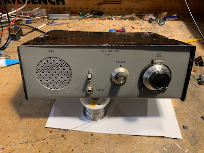
One of the first things I bought was the item pictured above. I bought it mostly because we are currently building 40 meter receivers with the local high-school students. I didn’t have a screw driver, so I couldn’t open up the box. Something was rattling around in there. I worried that the box might be mostly empty. Or that it would have one PC board with a sad collection of ICs. But in the hope that I would find something truly homebrew, I bought it.
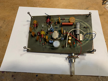
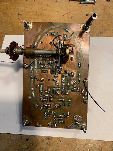
Below are pictures of what I found inside. Can anyone tell us what this is? ( I recognized it immediately.) More on this device in due course.
Other loot from the ‘fest:

The one on the left I’ve been using since around 1998! It is getting beat up. I bought the one on the right at the ‘fest. It is in much better condition. 5 bucks. TRGHS.

I always wanted one. I had nice leather case, but I gave it to Dick Dillman years ago. I now feel like a real boatanchor guy. I got for 15 bucks. I see on Amazon they are selling for $466!
I had one as a kid. Will be useful in the DR. In great shape.
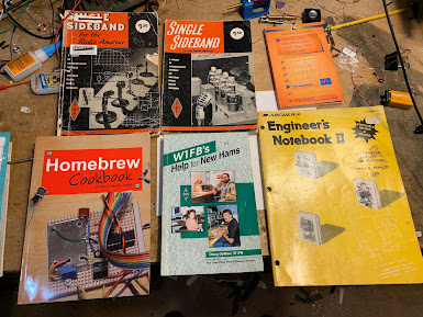
Eamon Skelton’s book was a great find. As were the early editions of SSB for the Radio Amateur. Eight bucks for the whole lot.
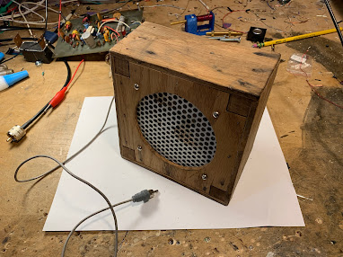
I like homebrew speaker enclosures. They add soul to the new machine. Perhaps a prize for the high-school project. Three bucks.
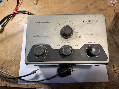
Finally, this thing. Plagued by guilt for past cannibalizations of QF-1s, I was going to pass on this one, but I realized that my friend Dean KK4DAS would be on his way, and if I didn’t take it (and extract the variable capacitor) he would. So I bought it. But I may leave this one as is, for possible use as the The Radio Gods intended. It could use some cleaning up. It seems to have a coat of nicotine. Ten bucks.
I also picked up a few larger knobs that may be of use with the high-school receivers.
SolderSmoke Podcast #244 PETE IS BACK! TR-7, CK722, BFR106, HP8640B, High-School Receiver, 10 Min TX, MAILBAG
SolderSmoke Podcast #244 Is available:
http://soldersmoke.com/soldersmoke244.mp3
Video version at:
HE’S BACK! HOORAY! PETE JULIANO N6QW IS BACK! SOLDERSMOKE COMMUNITY WAS SENT INTO A COLLECTIVE FUNK BY PETE’S ABSENCE. —————- Pete’s TR-7 (SEE VIDEO ABOVE) CK722 The BFR106
Pete’s new blog: https://hamradiogenius.blogspot.com/ —- Update on the high school project: Mixers made. Harder than they seemed. First QSO with the DC RX. Allan W4AMV Homebrewer TRGHS Ten Minute Transmitter – Better than the MMM! AF4K (SK) crystals. Other supporting projects: Farhan in Hyderabad. Rick N3FJZ, Walter KA4KXX, Andreas DL1AJG Electronics for Biologists. Peter Marks VK3TPM (fighting the siren call of the Si5351) . Steven VK2BLQ built a beautiful one. Daniel VE5DLD will build three of them with his students. Orlando PY2ANE is building one in Brazil. This week: The Bandpass Filter. (Thank you Hans Summers) — SHAMELESS COMMERCE DIVISION: BECOME A PATRON VIA PATREON. I am posting some fun stuff for the Patrons. AMAZON SHOPPING ADS Now on both the left and right columns. CHECK OUT Mostly DIY RF in the right hand column. —- My HP8640B Lives to Fight another day. Two new DMMs A low-end Fluke and a AstroAI 6000 Electrolytic Replacement Controversy Continues
Mailbag: — Dave AA7EE is blogging again! Yea! — Mike Rainey AA1TJ back in the Hobbit Hole Building a WWVB receiver. — Farhan is coming to FDIM. — Tony G4WIF reminds us that 39 bucks for JUST a 60 MHz counter would be great! — Dave VE3EAC again helped me fix my HP8640B. — Dean KK4DAS finalizing 10 meter DSB rig. FB. Upgraded my NanoVNA. — Mike KD4MM giving me a Nano VNA for the SolderSmoke Shack South. — Ian VK3LA asked what happened to Chuck Adams content. Good question. — Don ND6T and I have been discussing envelope detection. — Nick M0NTV working on AM modulators. He has a new video. — Ciprian YO6DXE built a Ten Minute Transmitter. — Steve EI5DD Connacht Regional News: https://www.docdroid.net/YJAV800/crnews0223-pdf
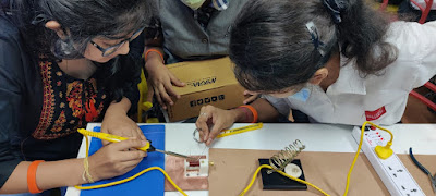
Hyderabad DC RX Workshop
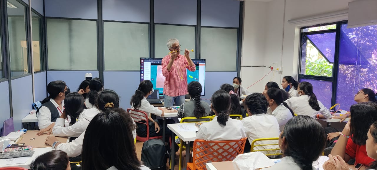
Farhan explaining the receiver in Hyderabad
My HP8640B Signal Generator Lives Again
I’d really come to like this old signal generator. The construction is superb. It was built to be repaired. As you open it up you find all kinds of useful diagrams and pointers. It is very solidly built – it looks like something that was built for the Apollo program. And it was given to me by a friend: Steve Silverman KB3SII gave it to me in 2017 — he had it in his New York City shack. Dave Bamford W2DAB picked it up for me just before Steve moved out of the city.
I’ve already done one complex repair on it — one of the tines on one of the selection switches fell of and I had to replace the tine. That was difficult, but it was a very satisfying repair.
But lately, the HP8640B started acting up again. It developed an intermittent problem that caused both the signal generator and the frequency counter to just shut down.
I was thinking that this might be the end of the road for the HP8640B. I even started looking for alternatives. But they were all very unappealing. They come in plastic boxes with names like Feeltech and Kooletron. The boxes are filled with flaky wiring and boards hot glued to the plastic. Yuck. The contrast with the HP8640B could not be stronger.
So I started to think about the problem. This was the first part of the troubleshooting process. I asked myself: What would cause several different systems (counter, frequency generator, and display) to all shut down? The power supply was a leading candidate.
I started reading the power supply section of the HP8640B manual. There was a line in there that caught my eye: The power supply boards had on them LEDs that glowed if the board was functioning. Thank you Hewlett Packard! I opened the top of the signal generator and found the power supply boards. Sure enough, there were the LEDs. I turned the generator on, and found that one of the lights was out. Bingo. (Trevor takes a look at the power supply boards in the video above. I have it cued up to the 12:57 point at which he talks about and shows these boards.)
Here was the other clue: The problem was intermittent. It kind of seemed like a loose connection. So I just unseated the board and took it out. I put some De-Oxit on the connector and popped it back in. Boom: The LED came on and the HP8640B came pack to life.
There is a whole bunch of great info and videos on the HP8640B on the internet. It is almost as if a cult has developed. This signal generator is worthy of a cult following. Count me in.
I especially liked the video below. Kevin really captures the admiration that many of us feel toward the way this piece of gear was built. He also kind of hints at the way this sig gen could become a pirate transmitter on the FM broadcast band (at 8:44):
I know that eventually the problematic plastic gears in this device might fall apart. I am prepared for this: I already have the metal replacement gears from India.
Thanks again to Steve Silverman KB3SII and Dave Bamford W2DAB for bringing me into the HP8640B cult.
A Couple of New Digital Multimeters: a Fluke and an AstroAI

Our high school direct conversion project made me realize that I really need to upgrade my digital multimeter. I’ve been using an old Radio Shack DMM that I bought about 25 years ago. It is OK, but it is not auto-ranging and it is starting to physically deteriorate. So off I went to Bezos-land.
First I spotted the Fluke 101. I was enticed by the brand and the low price. But when it got here I was a bit disappointed. It is really small — smaller than my cell phone. It is auto-ranging, and it does measure capacitance, but it doesn’t measure hFe and the frequency counter only goes up to 100 kHz. I couldn’t use it to measure the frequency of our DC receiver PTO. So, back to Bezos. (I’ll keep the Fluke as a toolbox DMM.)
Next I found the AstroAI True RMS 6000 DMM. Obviously not as prestigious as the Fluke, but both the Fluke and the AstroAI are manufactured in China. The AstroAI was really inexpensive: Like 34 bucks. And Amazon would do same day delivery here. Soon it was on my front porch.
I’ve only been playing with it for a day or so, but I really like it. It is auto-ranging, it has automatic shut-down, the frequency counter goes up to 60 MHz, it measures hFe and even has temperature sensor. The frequency counter had no problem measuring the output frequency of our DC RX PTO. The screen is big and bright. And I think the True RMS feature will be very helpful when I try to measure amplifier gain.
I like it. And you can’t really go wrong for the price. 34 dollars!
I have the Astro AI DMM in the Amazon ads on the right-hand column of the blog. I should have bought the package with the additional test probes. Click over there on the right for more info.
R-390s, KWM-2s, Airplanes, and Magnetic Loops — A Really Interesting Interview with Ted Robinson K1QAR
Eric Guth 4Z1UG has a really interesting interview with Ted Robinson K1QAR.
I really enjoyed hearing Ted’s inspiring story:
https://www.youtube.com/watch?v=SUUzlKMMANg
https://www.qsotoday.com/podcasts/K1QAR
Listeners will like the discussion of the R-390 and the KWM-2. And his talk about airplanes. And the joy of repair.
Here is Ted’s QRZ.com page: https://www.qrz.com/db/K1QAR
Thanks Eric! Thanks Ted!
Mr. Carlson’s New Lab and Workbench
I am very glad to see that Mr. Carlson is NOT slowing down. In fact he has built another lab and is ramping up. FB!
The TinySA ULTRA: Audio out! 200 Hz Resolution! Works Up to 6 GHz! Bigger Screen! (Video)
The improved resolution could be useful — we may now be able to see the sidebands coming out of a mixer that is producing AF out (as in a DC receiver).
The bigger screen is nice.
Looks like Dean and I will not have to modify our TinySAs for audio out. We will just upgrade to Ultra so we can listen in style to Vatican Radio and Radio Marti.
More info here: https://www.tinysa.org/wiki/
Thanks to Karl K5KHK for alerting us to the Ultra.
Watching Shortwave Broadcast Stations on the TinySA Spectrum Analyser
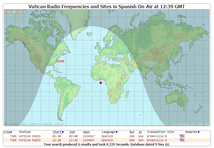
November 18, 2022 1244 UTC. I was using a TinySA spectrum analyzer to look at noise levels on the 40 meter ham radio band. I also wanted to take a look slightly above the band (in frequency) to see Radio Marti at 7355 kHz. As I was doing this I remembered that Vatican Radio was on the air at 7305 kHz from 1230 UTC to 1245 UTC. So was just going to catch the last moments of that day’s transmissions. Sure enough, I caught it, and watched it disappear from the TinySA screen. See the video above.
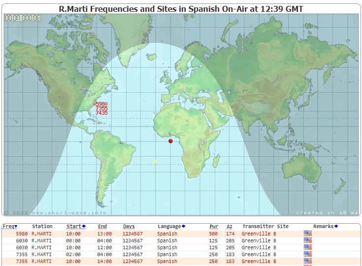
Radio Marti continued on. In the morning we can hear the rooster recordings from that station. We are using it to test how well our homebrew Direct Conversion receivers avoid AM detection. In the video I mistakenly said these two transmitters were on the air with 250 megawatts. The correct power is 250 kilowatts. Both transmit from Greenville NC. I think the signal from Vatican Radio is stronger here because they are using a different antenna pattern — Radio Marti is aimed at Cuba.

This reminds me of a cool project I have not yet done: modifying the TinySA to allow the user to listen to the station: https://soldersmoke.blogspot.com/2021/10/how-to-listen-with-your-tinysa.html I notice that Dean KK4DAS (my colleague in DC receiver design) was the only commenter on the blog post describing the TinySA mod. TRGHS. We need to to do this.
Here are the reports showing when Vatican Radio and Radio Marti were on the air on November 18, 2022:

Great Technical Info and Tribal Knowledge from GQRP

Thanks to Tony Fishpool G4WIF for sending us this link.
There is a lot of great tech info and Tribal Knowledge on the GQRP page. This is all related to our discussion of how to set up an electronic workbench or workshop.
Thanks Tony and thanks to GQRP.
Workbench and Workshop Tips — Please Put Suggestions in the Comments
During a recent visit to Barnes and Noble I picked up Adam Savage’s book (please use the Amazon link in the righthand column) about Making and workshops. Adam’s book reminded me of the importance of giving thought to the organization and set-up of your workbench or workshop. I found more tips on YouTube:
Wow, watch the KatVoltage video (above). Unlike the person in a recent unfortunate advertisement, Kat clearly knows which end of the soldering iron to grab. She is setting up a good workshop — you can tell from how she is organizing the bench. I wish her a lot of luck. htt(s://www.youtube.com/watch?v=1NcVzTu7TbE&t=54s
Andreas (the guy with the white glove and the Swiss accent) has some good ideas:https://www.youtube.com/watch?v=inW57njiq1A
The EEVblog guy has a good guide to the basic stuff that you need to build an electronics workshop. It is a bit dated (2011) but the guidance is still very good (I wouldn’t go with the homebrew or kit-built power supplies): https://www.youtube.com/watch?v=R_PbjbRaO2E
Van Neistat has a very good Top Ten List of things NOT TO DO in a workshop. NO FLATHEAD SCREWS. I’m with you Van. NO HOARDING. etc. https://www.youtube.com/watch?

New Video: Farhan’s Presentation on the “Daylight Again” Analog Transceiver
LOTS of tribal wisdom in this presentation by Farhan VU2ESE.
For more info, go to:
Putting the “Mate for the Mighty Midget” Back to Work — With a DX-100 on 40 Meter AM

After working on it for a while I got so fond of my old Hammarlund HQ-100 that I moved it from the AM/Boatanchors operating position over to a more convenient spot right next to my computer. This left a big gap on the receive side of the AM station.
I briefly put my HRO-ish solid state receiver above the DX-100, but I’m afraid that receiver needs some work. More on that in due course.
I thought about putting my SOLID STATE Lafayette HA-600A atop the thermatronic DX-100, but this just didn’t seem right. The Radio Gods would NOT approve.
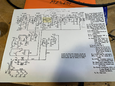
So I turned my attention to the Mate for the Mighty Midget that I built in 1998 and have been poking at and “improving” ever since.
This receiver worked, but not quite right. It received SSB stations well enough, but when I turned off the BFO I could no longer hear the band noise. I wasn’t sure how well the RF amp’s grid and plate tuned circuits tracked. And I had serious doubts about the detector circuit that Lew McCoy put in there when he designed this thing back in 1966.
As I started this latest round of MMMRX poking, I realized that I now have test gear that I didn’t have in 1998: I now have a decent oscilloscope. I have an HP-8640B signal generator (thanks Steve Silverman and Dave Bamford). I have an AADE LC meter. And I’ve learned a lot about building rigs.
FRONT END TRACKING
The MMRX has a tuned circuit in the grid of the RF amplifier, and another in the plate circuit of the RF amplifier. There is a ganged capacitor that tunes them both. They need to cover both 80/75 and 40 meters. And they need to “track” fairly well: over the fairly broad range of 3.5 to 7.3 MHz they both need to be resonant at the same frequency.
McCoy’s article just called for “ten turns on a pill bottle” for the coils in these parallel LC circuits. The link coils were 5 turns. No data on inductance was given. Armed now with an LC meter, I pulled these coils off the chassis and measured the inductances of the coils. I just needed to make sure they were close in value. They were:
L1 was .858uH L2 was 2.709 L3 was .930uH L4 was 2.672
Next I checked the ganged variable capacitors. At first I found that one cap had a lot more capacitance than they other. How could that be? Then I remembered that I had installed trimmer caps across each of the ganged capacitors. Adjusting these trimmers (and leaving the caps connected to the grid of V1a and V2A, I adjusted the trimmers to get the caps close in value. I think I ended up with them fairly close:
C1: 63.77-532 pF C2 64.81 — 525.1 pF
I put the coils back in and checked the tracking on 40 and on 80/75. While not perfect, it was close enough to stop messing with it.
DETECTOR CIRCUIT
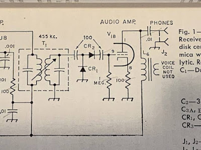
I’ve had my doubts about the detector circuit that Lew McCoy had in the MMMRX. In his 1966 QST article he claimed that the circuit he used was a voltage doubler, and that this would boost signal strength. But I built the thing in LT Spice and didn’t notice any doubling. And consider the capacitors he had at the input and output of the detector: 100 pF. At 455 kHz 100 pF is about 3500 ohms. At audio (1 kHz) it is 1.5 MILLION ohms. Ouch. No wonder years ago I put a .1 uF cap across that output cap just to get the receiver working.
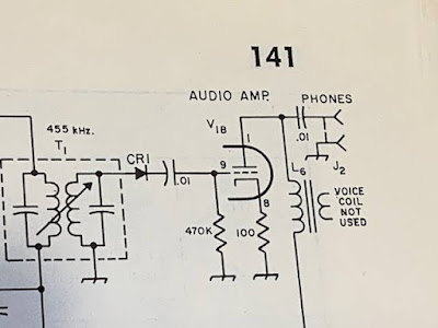
Scott WA9WFA told me that by the time the MMMRX appeared in the 1969 ARRL handbook, the second “voltage doubling” diode was gone, as were the 100 pF caps. Now it was just a diode, a .01 uF cap and a 470,000 ohm resistor. I switched to the 1969 Handbook circuit (but I have not yet changed the 1 meg grid resister to 470k — I don’t think this will make much difference). Foiled again by a faulty QST article, again by one of the League’s luminaries.
6U8s out, 6EA8s in
We learned that the 6U8 tubes originally called for by Lew McCoy are getting old and not aging well. So I switched all three to more youthful 6EA8s. This seemed to perk the receiver up a bit.
MUTING from the DX-100
My K2ZA DX-100 has a T/R relay mounted in a box on the back of the transmitter. When the Plate switch goes up, it switches the antenna from receiver to transmitter. The box also has a one pole double throw switch available for receiver muting. I put the common connection to ground, the normally connected (receive position) connect the ground terminal of the AF output transformer to ground — it is disconnected from ground on transmit. The other connection (normally open) is connected to the antenna jack — on transmit this connection ground the receiver RF input connection. These two steps mutes the receiver very nicely.
Replacing Reduction Drive
Over the years I have had several different reduction drives on the main tuning cap. I had a kind of wonky Jackson brothers drive on there that needed to be replaced. I put in a new one — this smoothed out he tuning considerably.
Ceramic Resonator
I never could get McCoy’s 455 kc two crystal filter to work right. So at first I made due with the two 455 kc IF cans. This made for a very broad passband. Then I put a CM filter in there. This was more narrow, but with a lot of loss. There may have been others. But the filter spot is currently held by a 6 kHz wide ceramic filter. This one is my favorite so far.
Digital Readout
When I was running the DX-100 with the Hammarlund HQ-100 I built a little frequency readout box. The box was from a Heath QF-1 Q multiplier (I am sorry about this). The readouts are in Juliano Blue and come via e-bay from San Jian. I now have it hooked up to the DX-100’s oscillator. I haven’t tapped into the MMMRX’s oscillator yet.
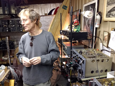
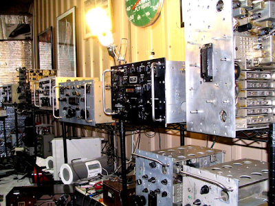
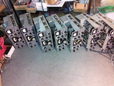
The Amazing Workshop and Test Gear of Tony Albus PE1ONS
This is almost too much. This makes me want to go out and buy some more test gear, maybe another scope, or a spectrum analyzer, or at least another DMM. I mean Tony has at least three of everything.
This is really amazing. Tony is obviously a test gear guy, but he also has a ham call PE1ONS. He says he is not too active, but we should encourage him to get more involved with ham gear. We need guys like him working on ham gear. And he seems like such a happy person.
Here is his QRZ.com page: https://www.qrz.com/db/PE1ONS
Here is his awesome YouTube channel: https://www.youtube.com/TonyAlbus
W1VD’s Boatanchor Receiver Tests

I’ve been trying to get more rigorous in my evaluation of receiver performance. My HQ-100 is tuned to Radio Marti, and it sounds great. But how great is it really? And what about all the receivers and transceivers I have built? How good are they?
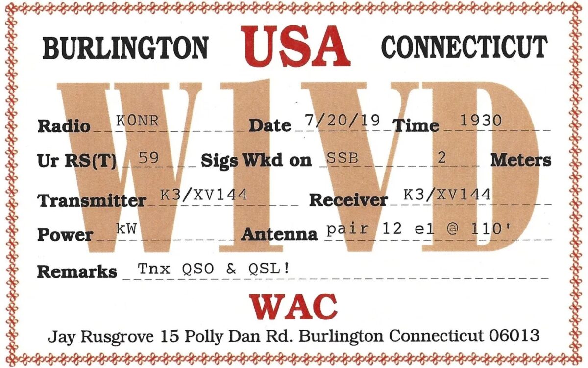
Our friend Dean KK4DAS is about to start the rehabilitation of his dad’s old HQ-170A. A search for that receiver led me to Jay Rusgrove’s very interesting measurement and analysis of old tube type radios. Jay’s results appear in the links below. More important is his very clear description of how the tests were done and what the results mean (link below). Also included is one link showing a discussion of Jay’s work.
Jay notes:
The decision of which boat anchor receiver(s) to own is seldom based on performance alone. A combination of favored manufacturer, period of manufacture, features, collectability or even just ‘looks’ often rank higher on the priority list than receiver performance. Even if one were interested in performance specs much of the available information is subjective as few receivers manufactured prior to the mid 70s have undergone standardized testing. Hard data on minimum discernable signal (MDS), blocking and two-tone IMD dynamic range is interesting to some operators and important in an historical context as it shows the progression of receiver development.
Jay designed the very first real transmitter that I homebrewed (The VXO 6 Watter from QRP Classics). Jay has been mentioned many times in the SolderSmoke podcast and blog:
Jay’s results: http://www.w1vd.com/BAreceivertest.html
Jay’s methods: http://www.w1vd.com/Receivermeasurementbasics.html
Discussion: https://www.antiqueradios.com/forums/viewtopic.php?t=96872
Level UP EE Lab Builds a Superhet Receiver
I was really glad to have stumbled across Darren’s YouTube channel:
Heck, he has an S-38E on the shelf above his bench. He is clearly one of us. What is his callsign?
This morning I watched the first and last of his 10 videos on his superhet receiver project. Very cool. Lots of good info in there. And there is something for everyone: Arduinos and Si5351s, along with a lot of standard analog circuitry. The first episode appears above.
The variable bandwidth filter looks very interesting. And there was a nice shout-out to Charlie Morris and one to Hans Summers.
I really like his effort in episode 10 to measure Minimum Discernible Signal using commonly available test gear. This helped me in my effort to get more rigorous and serious about receiver performance measurement.
Darren has many other excellent projects on his YouTube channel. My Hammarlund HQ-100 receiver started giving me trouble this week, and I was debating whether or not to fix the old thing. Darren’s channel provided the inspiration I needed. It will be fixed!
Please subscribe to Darren’s channel. And spread the word about his videos. We definitely want him to make a lot more.
Thanks Darren!
Windsor (England) Signal Generator (from Slough) with a Very Cool Dial

Kilo Cycles! Mega Cycles! Windsor – like in the castle! Made in Slough, Buckinghamshire, England, the town that was the fictional site of the original (UK) version of the TV series “The Office.” The dial and indicator turn nicely.
I would be willing to part with this piece of kit. Please let me know if you are interested, how much you would offer, and how we could arrange shipment.