How to Get Ready to Build a BITX-20

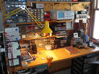
Continuing with our workshop inspiration theme, I spotted this in the BITX-20 mailing list this morning. The response is from Farhan:

blake,

i would suggest a different route. a long and winding one, that will
finally lead to a bitx.

the idea is to learn. you do this by understanding what you build and
building what you understand. by ‘understand’, i specifically mean, being
able to measure. here is what i suggest, buy yourself a bunch of 2N3904s
from the local radio shack and some resistors and caps. then build this :

http://www.phonestack.com/farhan/testosc.gif

this is an oscillator. if you plug a coil between the open ends, it will
become a vfo, if u plug a crystal, it becomes a crystal oscillator. you can
use your frequency oscillator to check the frequency it is oscillating at,
etc.

with this, you would have mastered the first of the three blocks that make
up almost every radio circuit. but next, you must make another test
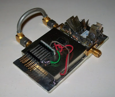
instrument. a power meter. most of us ham start out with a simple RF probe.
while that was fine and dandy for its day, now we can do much much better.
we can make a very accurate power meter that enable you to measure things
as finely as anybody in this business. W7ZOI has designed a super simple
power meter. it is available as a kit.
read about the power meter here :
http://www.kangaus.com/Documentation%20files/Power%20Meter%20Documentation%20May%202011.pdf
you can purchase the kit at www.kangaus.com
(I have no business interest with kanga or any other kit manufacturer)

with the power meter in place, you can now measure the power levels coming
out of any circuit with great accuracy.

now, you can build a single stage feedback amplifer (there are six of them
used in the bitx) on a copper clad board. using the test oscillator as an
input, you can measure how much gain the amplifer has (measure the
oscillator output, then connect the oscillator to the amp and ,measure the
amp output. the, amp output – oscillator output = amp gain).

of course, while building both these blocks, you will discover what
voltages to expect at which junction of components in both these blocks.

next, you can build a step attenuator. which is a really simple thing and
of immense value in the home lab. here is a design
http://www.arrl.org/files/file/Technology/tis/info/pdf/9506033.pdf
or you can now buy it in a kit form from
http://www.qrpkits.com/attenuator.html

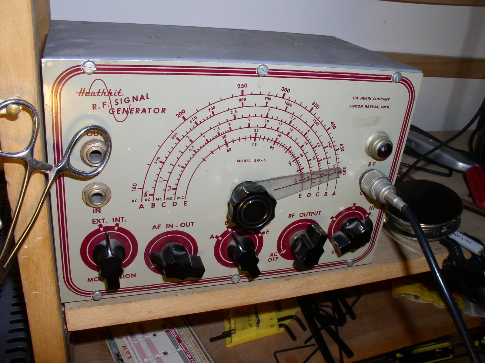
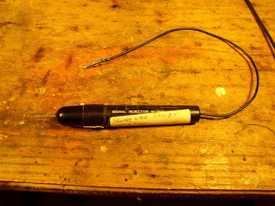
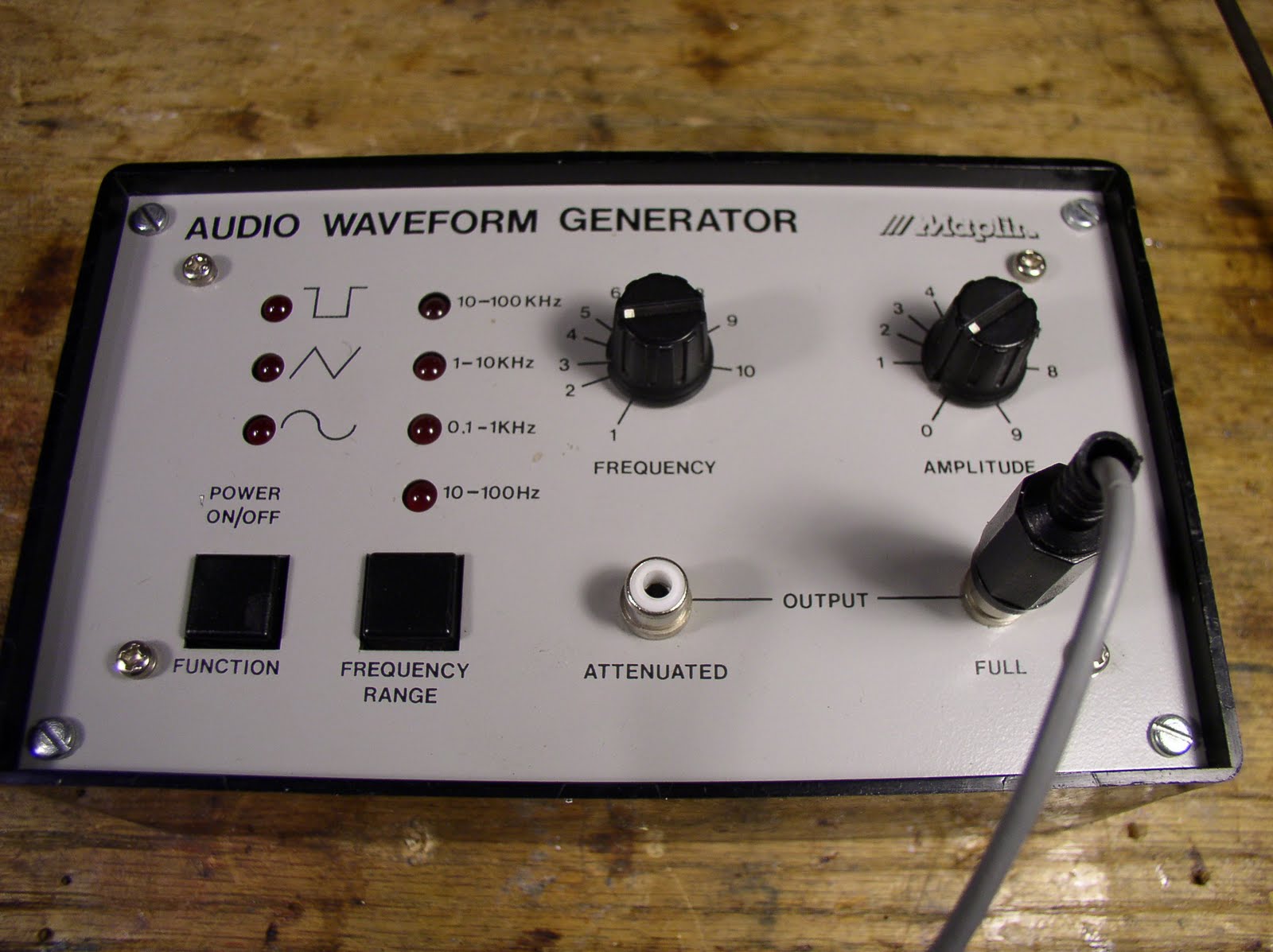
finally, you can build a simple signal generator like this :
http://www.phonestack.com/farhan/siggen.html . this will allow you change
frequencies and measure what a circuit does at different frequencies. you
can use this to test how the filters are doing and get them to ‘spot’ where
you want them to.

so, there it is, a signal generator, a power meter, step attenuator, test
oscillator. four, very simple test instruments that you can build
yourself. they will give you one helluva education in radio. and within
weeks, you will understand and start building on your own!!

– farhan


> Quoting bfabman :
>
> Hello Everyone, I have been watching the group for a few months now
> with interest. I have no electronic experience to speak of, but I have
> a burning desire to make one of these, and I am wondering what all of
> you think of someone like myself building one as my first real radio
> project, to be used for qrp mountain topping. I don’t have any
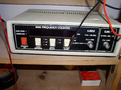
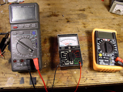
> electronic test equipment for the final alignment, other than a
> standard DIG vom meter. (I am willing to buy some equipment if
> necessary) I think that this would be an awesome winter project just
> don’t know if it would be over my head. If I got it all built, could I
> actually get it aligned and working properly. I did make a Norcal
> frequency counter project last year and it turned out very well. Thanks
> for your opinions before I spend the money. Blake
>
> Paul Daulton K5WMS
> beacon WMS 185.302 khz qrss30/slow 24/7
> Jacksonville,Ar 72076
> em34wu

Our book: “SolderSmoke — Global Adventures in Wireless Electronics” http://soldersmoke.com/book.htm Our coffee mugs, T-Shirts, bumper stickers: http://www.cafepress.com/SolderSmoke Our Book Store: http://astore.amazon.com/contracross-20

EDN Article on Performance of Modern Ham Transceivers

Mike, KC7IT, alerted us to a very interesting EDN article about the performance of modern ham transceivers:
http://www.edn.com/article/521690-High_performance_HF_transceiver_design_A_ham_s_perspective.php?cid=Newsletter+-+EDN+Fun+Friday


On the phase noise, how do old fashioned LC or crystal oscillators compare to modern PLL or DDS circuits?


And congrats to Elecraft for the high ratings on their K3.

Our book: “SolderSmoke — Global Adventures in Wireless Electronics” http://soldersmoke.com/book.htm Our coffee mugs, T-Shirts, bumper stickers: http://www.cafepress.com/SolderSmoke Our Book Store: http://astore.amazon.com/contracross-20

Evil Mad Scientist Builds a Heathkit

You guys will get a kick out of this: An old unbuilt Heathkit is discovered, and is then put together by “Evil Mad Scientist.” EMS obviously loves electronics, but is clearly of the digital/IC generation: “The tubes are gorgeous! Their exteriors are glass with electrodes extending from the bottom!” Wow.

The Evil Mad Sci guy fears that the solder provided by Heath will have “gone bad over time” and says that he will use “more modern solder.” Hold your horses Frankenstein! Don’t you dare put that Heathkit together with lead-free solder! That could tear a hole in the fabric of space time! Also, I dunno about the idea of putting all the components on the lugs and rotary switch terminals first, with all the soldering coming later. The boys at Benton Harbor wouldn’t have liked that. And you might want to gradually bring the voltage up on that big electrolytic cap up using a variac. Which brings to mind some needed advice: BE CAREFUL! You have moved out of the realm of 12 V DC. That old Heathkit could zap you good!

http://www.evilmadscientist.com/article.php/heathkit-part1


Thanks to Mike Butts for alerting us to this.

Our book: “SolderSmoke — Global Adventures in Wireless Electronics” http://soldersmoke.com/book.htm Our coffee mugs, T-Shirts, bumper stickers: http://www.cafepress.com/SolderSmoke Our Book Store: http://astore.amazon.com/contracross-20

Hans Summer’s Homebrew ‘Scope

The picture right away gives you a sense of the depth of this project, and of the guy who completed it. One of my biggest mistakes in the UK was missing the opportunity to meet Han Summers, G0UPL. Check out Han’s Homebrew ‘scope project, and be sure to look around his site for other, similar adventures:


http://www.hanssummers.com/tinyscope.html

Our book: “SolderSmoke — Global Adventures in Wireless Electronics” http://soldersmoke.com/book.htm Our coffee mugs, T-Shirts, bumper stickers: http://www.cafepress.com/SolderSmoke Our Book Store: http://astore.amazon.com/contracross-20

EE Web Featured Engineer: Alan Wolke, W2AEW

I really liked this interview with our friend Alan. You can see definite signs of an early case of The Knack here: I was especially impressed by the fact that he made one of his first antennas from wire salvaged from the deflection coil on an old TV. (I took the easy path and chopped up my dad’s extension cords!)

I also liked Alan’s response to the question about his favorite software tool: “Gee, solder is soft, can we consider that software? I use a lot of that!” This is very reminiscent of a quote from the legendary Bob Pease (colleague of Jim Williams): “My favorite programming language is solder.” (That quote was sent to me by Steve WA0PWK. Thanks Steve.)

Lots of good troubleshooting wisdom in this interview, and Alan’s enthusiasm for electronics clearly shines through:
http://www.eeweb.com/spotlight/interview-with-alan-wolke

If you’re also interested in the field of electronic repairs, visit www.guidetocareereducation.com for a list of schools offering electronics and engineering training programs.

Also, be sure to check out Alan’s YouTube videos, especially those on how to use an oscilloscope:
http://www.youtube.com/user/w2aew


Our book: “SolderSmoke — Global Adventures in Wireless Electronics”http://soldersmoke.com/book.htmOur coffee mugs, T-Shirts, bumper stickers: http://www.cafepress.com/SolderSmokeOur Book Store: http://astore.amazon.com/contracross-20

New Oscilloscope!

That, my friends, is a genuine dual-trace, 100 MHz Tektronix oscilloscope. Wow, a new day has dawned on the N2CQR workbench! The ‘scope comes to me as a result of the generosity of friend who, like the guy in the old “Millionaire” TV show, prefers to remain anonymous. He claims this is an equipment trade, but the terms were so one-sided (in my favor), that this was really a gift.

As you can see below, the ‘scope fits perfectly in the center position on the shelf above the bench. I’ve already put it to work — here you see it looking at the output from the VFO of the kick panel rig.

Our book: “SolderSmoke — Global Adventures in Wireless Electronics”http://soldersmoke.com/book.htmOur coffee mugs, T-Shirts, bumper stickers: http://www.cafepress.com/SolderSmokeOur Book Store: http://astore.amazon.com/contracross-20

The “Snort Rosin” Test Gear Philosophy

Steve Smith, WB6TNL, and I often find ourselves on the same frequency:

Hi Bill,

After reading your latest blog post, I realized that you and I are somewhat kindred spirits. You successfully build and test relatively complex amateur radio equipment using the most basic and inexpensive test equipment.

As part of my business (land mobile radio) I own expensive and complex test equipment, however when I build and test homebrewed amateur radio gear I prefer to use inexpensive home-built or kit-built test equipment because that is what is generally available to most hams. My philosophy is that it is very important to impress upon beginning homebrewers the fact that fancy, complex test gear is not absolutely necessary to be successful in homebrewing.

Perfectly functional test gear can be built using only basic electronic tools. Certainly, homebrewed equipment might not have all the ‘bells and whistles’ of commercial gear and won’t do everything ‘automagically’ but with careful calibration and learning how interpret the results, homebrewed test equipment can provide very accurate measurements.

One good example is your Palomar R-X Noise Bridge. Most every ham wants a MFJ 259B or Autek VA-1 antenna analyser but an inexpensive bridge like the Palomar or a homebrewed equivalent can provide many of the same measurements. Sure, a ham-band or general-coverage receiver is required to use a noise bridge but, by using -very- simple circuits, a very competent test receiver can be built using the most basic test gear. Even with only a good SWR meter and a little math thrown in, +/- Xj (reactance) measurements can be made (See http://www.qsl.net/n8xpv/ for information regarding “the 3 meter method” ).

One of my favorite resources for simple test equipment is Monty Northrup’s (N5ESE} site: 73…….

Steve Smith WB6TNL “Snort Rosin”

From:

To:
“Steve Smith”


Great message Steve. Yea, I think the best troubleshooting tool is a real understanding of what is happening (or supposed to be happening) in the circuit and an ability to think logically about what could be causing the problem. Technical detective work.
And indeed, that SWR bridge can tell you a lot.
73 Bill

Our book: “SolderSmoke — Global Adventures in Wireless Electronics”http://soldersmoke.com/book.htmOur coffee mugs, T-Shirts, bumper stickers: http://www.cafepress.com/SolderSmokeOur Book Store: http://astore.amazon.com/contracross-20

Test Gear/Workbench Maintenance

I mentioned in the last podcast that I was going to take a break from construction projects and spend a little time fixing up tools, test gear, and the work bench. First up was my old soldering gun. I bought this thing almost 40 years ago! It is pretty beat up, but I managed to patch it up and it now works fine. Even the original light bulb works.

I use this little AADE L/C meter a lot, but was having trouble getting parts across the test terminals. So I soldered alligator clips onto one of the parts connectors that came with the device. Makes testing easier.

Just a little audio oscillator. Puts out .2 volts at 713 Hz. Useful for testing the phone rigs.

I picked up this little Lafayette power supply at a hamfest and found it quite useful. But then I managed to knock the needle off the meter while fooling around with trivial electric motor. Any ideas on where I could get a replacement meter movement, or on what value I should use?

Here is a wave meter that I picked up at the Kemptom Park rally in London. Apparently at one point all UK radio amateurs were required to have one of these devices. I’m tempted to chop it up for parts. That variable cap with the reduction drive looks promising. And could that meter solve my problem with the power supply (above). If anyone can think of a reason to keep this as a wavemeter, please let me know.

Further proof of my extreme retro-ness. This is what I use as a signal generator. A Heathkit SG-6. Older than me!

This is my scope. HAMEG. Supposed to be good to 10 MHz but of course I can use it at higher freqs (which I do). I need to upgrade. Any suggestions?

A very useful little square wave generator.

I need to make more use of this noise bridge. Lots of potential here.

Obviously a London purchase. Very useful little AF sig generator from the UK’s equivalent of Radio Shack. My only complaint: No auto-off. I forget to turn it off and run down the two 9 V batteries.

Long time listeners will remember this device. This is the one in which I soldered in the chip upside down. It works fine on th 5 Hz to 100 MHz range. Dead on the 4 – 600 MHz position.

I bought this power supply at the Kempton Rally, then converted it into a current limited supply using a chip and a circuit provided by Tony, G4WIF. My daughter Maria helped paint the cabinet. Lots of soul in this little machine.

Just three meters. The middle (analog one) is still very useful, and has considerable sentimental value for me — my wife got if for me when we were back in the Dominican Republic.
My version of the W7ZOI power meter. Mike, KL7R, and I built versions of this device back in 2004 or so.
This is Cappuccio. He joins me in the shack most mornings. I’m not really a dog person, but I’m growing fond of him, even though he occasionally eats resistors and capacitors.

Our book: “SolderSmoke — Global Adventures in Wireless Electronics”http://soldersmoke.com/book.htmOur coffee mugs, T-Shirts, bumper stickers: http://www.cafepress.com/SolderSmokeOur Book Store: http://astore.amazon.com/contracross-20

Colin’s Power Meter


Hi Bill,

Thought you would be interested in the attached pics, one shows a power meter that a colleague made for me. I had mentioned to my colleague about the W7ZOI power meter after listening to SolderSmoke at work. A couple of days later I was presented with a power meter constructed from scrap parts! We work for a company that repairs cell ‘phone base station equipment and the power meter was made from some scrap VSWR monitor circuits. My favourite part of the device is the heatsink fins on the 30dB attenuator along the top, which can be taken out of circuit by removing the SMA link. To use the meter, the 8V regulator is powered up and if any RF is present at the RF in, a voltage, which can be read by an external Volt meter, is output via the multiway connector. I use a ribbon cable, which has three connections used, DC (+&-) and meter test point. A graph plotting RF in against Volts out can then be used to determine measured RF.

The second pic shows a QSL card for a 17m CW contact I received for my contact with Ronny SM4RRF. I was using a low dipole and 500mW from an FT817! This was my 2nd ever CW contact.

73 and keep up the good work at SolderSmoke.

Colin M0CGH

More Workbench Eye Candy

I blame Rogier for the title of this post. He saw yesterday’s workshop pictures and declared them to be porn-like. We all know what he means. Gil sent me this link with more workshop shots: http://www.crystalradio.net/bench/index.shtml
I really like the one above. It is from Catalonia in Spain. It belongs to Josep Busquets Vinas.
One question about yesterday’s slide show: Where’s the WD-40?

The Joy of Fixing Broken Gear

Alan, WA9IRS, sent in this really great link about Jim Williams, an engineer who writes for EDN. In his article Jim captures better than anyone the joy of repair.

Those taking up an engineering degree online can use the tips included in his book.

Check out his article: “Try Fixing it Yourself.”
And if you like the article, check out Jim’s book: Another Look at Analog Circuit Design

Calibrating my W7ZOI/W7PUA Power Meter

In the course of testing my 20 meter DSB rig, I discovered that the chart I prepared for my
W7ZOI / W7PUA power meter had some problems. In my first effort to get some calibration points, I used a simple diode and cap peak reading signal probe to measure voltage across 50 ohms, but I may have neglected to convert from peak to RMS before calculating the power. That would certainly mess up the chart!
This morning I used my old Heathkit SG-8 signal generator and my HAMEG (20 Mhz) ‘scope to get a couple of points for my graph of the response curve (line) for my meter.
I drew the new line, then used my trusty HW-8 at 1 watt to see if my chart was accurate. It was right on the money!
I look forward to happily measuring milliwatts with this very FB piece of test gear. See the June 2001 issue of QST for more details. Thanks to Wes and Bob for the great project. And thanks to Thomas in Norway for sending me the AD8307 chip.