National Dial and Gearbox Problem Resolved

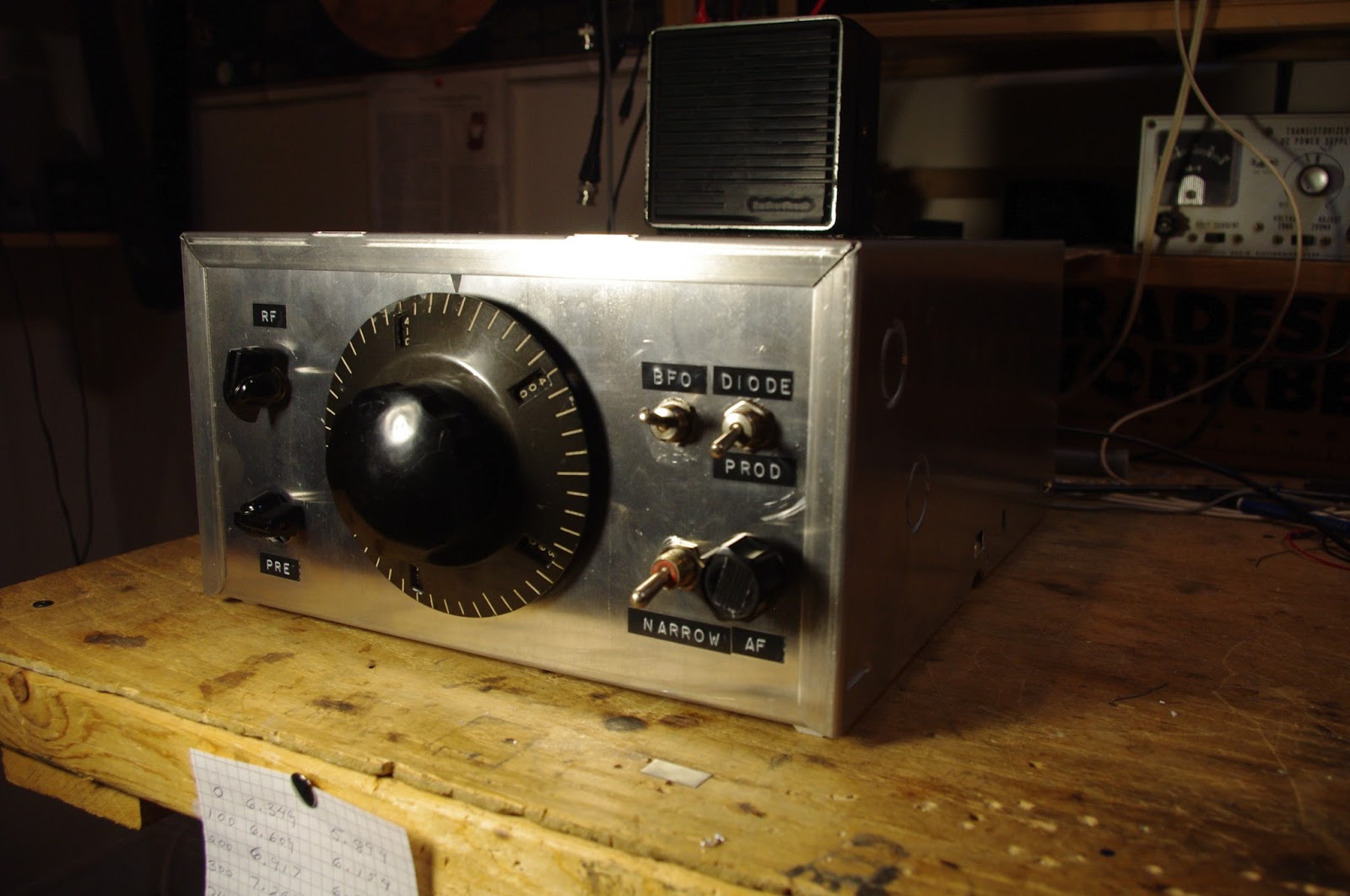
Thanks to all who offered advice and assistance. With help from you guys — and especially from Pete Juliano N6QW — I think I have this fixed.

Pete was right — the problem was really with the variable capacitor. The one I was using was kind of stiff and irregular in its motion. I found another one in the junk box that was easier to turn (it has one set of ball bearings). This fixed most of the problem.

I also spent more time making sure the shaft of the cap lined up perfectly with the shaft of the gear box. This also helped a lot.

I realize now that some of the “stickiness” that I occasionally feel while tuning may be coming from the dial — not from the gear box. It looks like my dial took a hit that slightly bent one portion of it. It seems that the numbers have a bit of trouble clicking over on that portion of the dial. Some lubricant may help there. But I can live with it.

The receiver now tunes very smoothly and I can go right back to a frequency and find the signal exactly where I left it. There does seem to be a very slight difference depending on whether I “approach from above” or “approach from below” — but this is not a big deal.

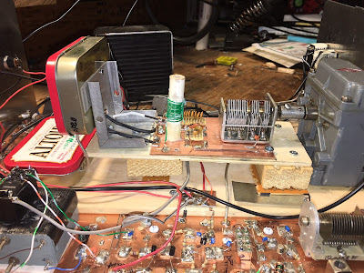
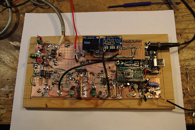
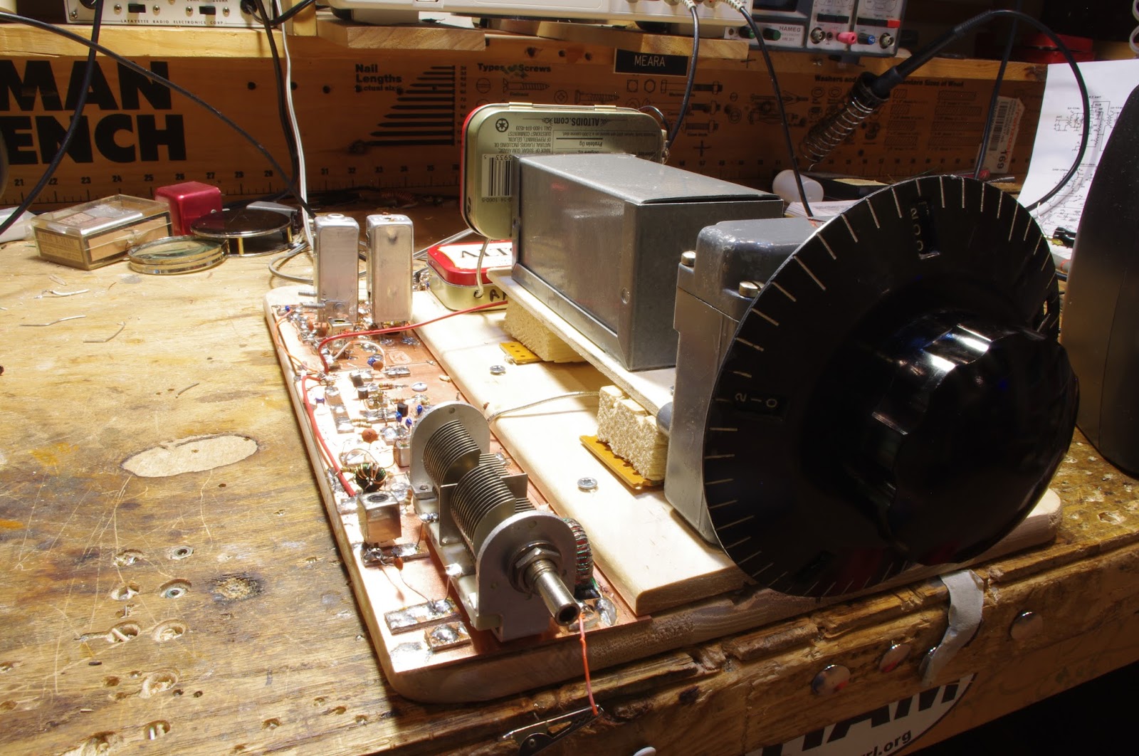
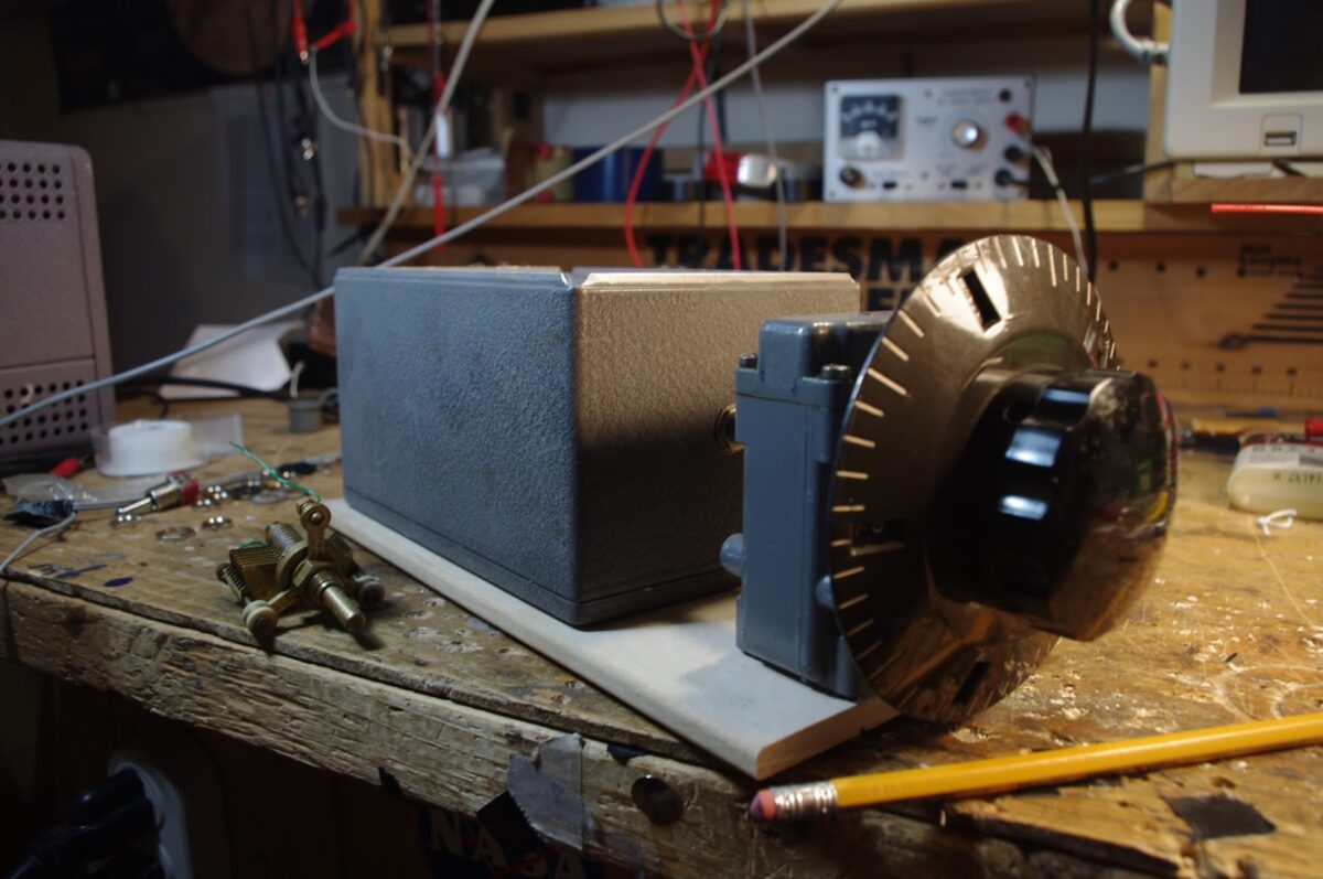
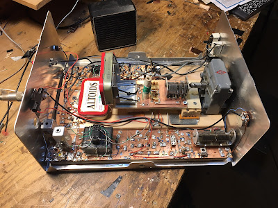
Check out the pictures of the receiver and the VFO. Note the “cardboard from a coat hanger” coil form. The winding is held in place with nail polish varnish. I had planned on having the variable cap, the coil , and the associated fixed caps all in a box for better thermal stability, but the VFO is very stable even without the box. I have the VFO running 455 kc ABOVE the signal frequency. It runs from about 7455 kc to about 7800 kc. I could have set it up to run 455 kc BELOW the signal freq. That would have made it a bit more stable (it is easier to attain VFO stability at lower frequencies) but VFO is so stable that I probably won’t mess with it. I followed DeMaw’s rules: Physical stability, NP0 caps. For the NP0 caps, put several of them in parallel to get the desired capacitance value. Keep heat-producing active components away from the coils and caps.

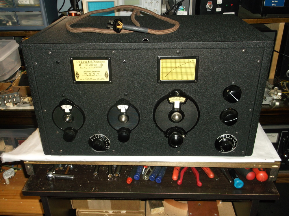
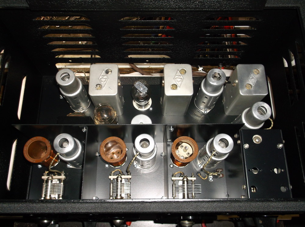
Thanks again to Armand WA1UQO for giving me this amazing piece of radio history. And thanks to Tim Sutton for the big box that holds this receiver.

James Millen knew what he was doing. See: http://www.isquare.com/millen/millen-page.htm

F5LVG’s Nail Board Receiver — Names for the Technique


Pete WB9FLW reminds us that Olivier F5LVG has LONG been using copper nails and wood boards to build amazing rigs. See above for one magnificent example. That, my friends, is a superhet receiver. Inspirational!


A few posts back we asked for nominations for the official name of this technique. We still have to consult with Steve Silverman on this, but the nominations are:

Armand WA1UQO (perhaps reflecting his proximity to Washingotn DC) “Wire-Tapping”

Gary Hinson: “Coffin Dodging” (sounds a bit dodgy to me).

And the front runner so far, from Melbourne, Australia — drum roll please:

Peter Parker: “NAILBOARDING.” (Peter thinks he nailed it with that one. I tend to agree.)

An Old but Cool DiFX: The Epiphyte


I’ve been hearing about this rig for many years. It first appeared in the September 1994 issue of QRPp, the journal of the NORCAL QRP club. A condensed version of that article appeared in SPRAT 81 (Winter 94-95). The designer is Derry Spittle VE7QK from Vancouver, British Columbia.

The name always puzzled me. Here is the explanation: It started with the Neophyte: A very simple direct conversion receiver that many of us built. The Neophyte was mostly an NE602 and an LM386. In the Epiphyte, a crystal filter and a second NE602 were added, turning the Neophytes into a superhet receiver and — with some additional circuitry — an SSB transceiver. The Oxford English Dictionary reportedly defines an Epiphyte as “a plant that grows on another plant”(see picture below). The Epiphyte grew out of the Neophyte.

And this plant grew in British Columbia, which seems — like Australia and New Zealand — to be fertile ground for simple phone rigs. I’m pretty sure the “Wee Willy” DSB rig also came out of BC, and it may have had a similar purpose: allowing for portable contact with the BC Public Service Net on 75 Meters.

There are many features of the Epiphyte that I like: There is a simple 455 kHz filter and a ceramic resonator BFO/Carrier oscillator. The original design featured a VXO-like circuit using a ceramic resonator at 4.19 MHz. And it ran off AA batteries (as did the NE602 DSB rig I took to the Dominican Republic).

Unlike my NE602 rig, the Epiphyte made an artful use of the fact that NE602’s can be set up to have TWO inputs and TWO outputs. Where I used DPDT relays to switch inputs and outputs from both NE602s, OM Spittle left all the inputs and outputs connected, and simply switched the VFO and BFO signals. Ingenious.

There were updates and improvements. The Epiphyte 2 and 3 featured increased power out (5 watts vs. 1 Watt). Version 3 has an IRF-510 in the final, driven by a CA3020A chip. That chip is capable of 70 db gain. Wow.

In 1996 NORCAL and G-QRP donated 50 EP-2 kits to radio amateurs in third world countries. Very nice.

In 2000 NORCAL did a kit of the EP-3 — it sold out in 24 hours. Here is a nice article on the EP-3:
http://www.norcalqrp.org/files/Epiphyte3Mnl.pdf

And above we have a video from Japan of an EP-3 in action.


Another Thermatron Receiver (video)

Thanks to Steve N8NM for sending this along. He said it seems to be crying out for a synthesized VFO — I disagree,of course.

I like the filter arrangement — one crystal at 455 kHz, two tune-able IF cans and a phasing control. This seems like a good way to get both AM selectivity (broad) while still having the ability to narrow the bandpass for SSB.

The builder did a great job. Does anyone know who he is?

The Soul of the Old Machine

I continue to peruse the stack of Electric Radio magazines that Armand WA1UQO gave me last month. Great stuff. I’m really struck by how much of our ham radio history is captured in the pages of ER… and nowhere else. This is a resource that should be protected.

In the last podcast I shared a few lines from the “Amateur Radio SSB — The First Fifty Years” series or articles. Today at lunch time I was reading the March 1994 issue, there was an article by Don Meadows N6DM entitled “A Homebrew CW Receiver.” From the last paragraph:

“This homebrew receiver as the main station receiver until 1975… In 1989 the homebrew receiver was finally mothballed… In its place I acquired an imported box that does everything. This box is friendly and cooperative, but I have no rapport with its soul. When it ultimately falters, it will need to be cured in the manufacturers sanitarium for sick gear instead of on my own workbench.

I’ve always been proud of this homebrew receiver. It did its job exceedingly well. Retrieving recently this old friend from storage for photographs, cleaning out the dust and dead insects, inspecting its wiring up close — all this evoked fond memories.”

N6ORS’s Franken-SDR Superhet

Of course, I love it. MOSFETS! NE602’s! 10.7 Mc IF cans! Cycles, not hertz! And a Tayloe Quadrature Sampling Detector made from junkbox parts from the Reagan administration. FB Keith. And the frequency display is icing on the cake.

Bill:

I thought the group might find my new Franken-SDR interesting.
It is an SDR with a superhet front end.


I wanted to play with an SDR but I didn’t want to get a kit or buy
parts, so I scrounged through he drawers and found a mux chip
cd-4016 circa-1980 some old 7400 logic that is probably per-1980.
This could make a QSD but only very low frequencies. Well I thought
how about at IF frequencies?


The frontend is a MOSFET mixer (1975) , the 10.7 IF is a dual gate MOSFET
(1975), the second mixer is a NE602, the IF cans are all stagger tuned to
give a bandwidth of 50kcs.
The only thing modern is the DDS but I old-time-ifyed it with BCD switches.


Keith N6ORS


VK6FTH did something similar: http://www.vk6fh.com/vk6fh/SDRradio.htm

NE602 Si5351 OLED “Whole Foods” Receiver

This is one of those projects that sort of just happened. First I built an Si5351/Arduino synthesizer with a small OLED I2C display (program by Thomas LA3PNA — thanks Thomas). Tom Hall AK2B up in New York helped me get the Si5351 VFO and BFO going — thanks Tom. Then, over the holidays I decided to build a rig of some sort around the Si5351. I started with a superhet receiver using an NE602 as the mixer and another as the product detector. I power the NE602 with an 8 volt regulator from W8NSA — thanks Jim. I made a 4 crystal 11 MHz Cohn filter using crystals left over from a BITX project. The software from AADE helped me design the matching networks to match the filter to the 1500 ohm impedances of the NE602s. I built the circuits on a milled board sent to me by Pete Juliano N6QW — thanks Pete! I put a dual tuned circuit at the front end, going into a MOSFET RF amplifier. For audio amp I have an LM386. The whole thing is screwed down to a barbeque grilling plank from Whole Foods — thanks Whole Foods! (This seems appropriate — the “O” in OLED is for “Organic”!)

It sounds nice. I may eventually try to put some relays in to switch the NE602s and the filter around to make this a transceiver.

NO3M’s Amazing Homebrew 1934 Single Signal Superhet

Jim AB3CV reminded me this morning about the work of Eric NO3M. Jim was pointing out that breadboard construction need not be ugly and that Eric’s work is the proof of that. Indeed.
Almost one year ago, I worked Eric on 160 meters. He was using one of his beautiful breadboard rigs:
Jim’s reminder sent me once again to Eric’s site. I see he has been melting a lot of solder, and to very good effect. In just three weeks he built the magnificent 1934 QST “Single Signal Superhet” pictured here.
Eric has a great series of articles on this project, with excellent pictures and videos:
Bravo Eric!

Boxed-up and Looking Good: An End to “HRO Al Fresco”

The “al fresco” phase has ended for my HRO receiver project. As has happened with homebrew projects around the world, this rig was literally pushed aside on the workbench to make room for BITX-40 Module Mania. I began to worry that the circuitry of the HRO receiver might suffer damage from the various kinds of electronic construction mayhem that take place on our workbenches. Also, I wanted to see what it would look like in the nice big metal box that Tim Sutton had sent me (thanks again Tim.) And I was hoping that the box would help with the AM broadcast breakthrough that I sometimes hear with this receiver. So, as you can see, I have good excuses for declaring Basta! on the HRO Al Fresco.

I think it looks great. Black on silver is very cool. It sounds great. I’m listening to 40 right now. Thanks to Armand WA1UQO for the very cool HRO dial that got this all started.

Cool Jazz from New Zealand as Heard on a Homebrew Superhet Receiver (VIDEO)

I’m making slow but steady progress on this one. The origin of the project was the beautiful National HRO dial and gearbox that Armand WA1UQO gave me.

I decided to use a 455 kHz IF because;
1) That was the IF of the old HRO receivers (the ones that won WWII)
2) I had a nice TOYO CM455 crystal mechanical filter that would be good for SSB.
3) I figured it would be easy to add in a wider filter that would be good for AM shortwave listening.
4) I like to keep the IF below the frequency of the VFO.

The wide filter turned out to be harder than I thought, but I think I have finally achieved the selectivity I was looking for. I’ll have a switch on the front panel that will allow me to go from “AM-Wide” to “SSB Narrow.” The switch will change the filters and the detectors, and will turn the BFO on and off.

Still to do: I need a high-pass filter to knock down RFI from nearby AM broadcast transmitter. And an RF gain control would be nice.

I’m really glad Radio New Zealand is there. It provides welcome relief from the shortwave fire and brimstone. Radio Romania is also doing a fine job on shortwave.

Colin M1BUU’s New Receiver Project


Hi Pete,
Just checking in 🙂
I have actually been melting solder recently. I decided to build a little CW receiver. I love my regenerative RX that I built as a teenager, but after all these years, I’m tired of constantly tweaking the controls!
My project is a 20m CW only superhet receiver with a 9MHz home brew filter. I’m using the SI5351 for the oscillators. I originally thought I would cover multiple bands, but for now I have the parts for 20m coverage. I might tinker with other bands at a later point.
I’m using your LBS code on the Arduino, the one for 20m with 9MHz IF. I haven’t applied power to the rig yet but it’s not far off fully built. I tweaked the Arduino sketch using my Uno and tonight I have successfully transferred the code to a Pro Mini. (Code went into Pro Mini on first attempt – amazing!).
73 for now,
Colin M1BUU


Beautifully Ugly! A Homebrew Receiver from the Netherlands (video)

This one is similar to the receiver I’ve been working on: middle of the HF band, discrete components, all analog, 455 kc IF, wooden chassis, eclectic circuit boards. Very cool.

The builder is Ko Tilman. His YouTube channel is here:
https://www.youtube.com/channel/UCqe1Y4StR9cZ8BQDWuoMq9w

I came across Ko’s channel when I was looking for a circuit for an AM detector. I have been experimenting with the standard one diode and two diode (Germanium) circuits, but the receiver doesn’t sound very good when using these circuits. Any recommendations for something a bit better (without getting carried away with complexity)?

About Ko Tilman:

Ko Tilman (1955) lives in the Netherlands and is active in electronics since 1967. His focus is on analog electronics, audio, shortwave radio’s, small (solar) energy systems and measurement and control systems. He is the author of “Retro Radio”, Isbn 978-90-5381-234-1, published by Elektor International Media in the Netherlands. In this book (Dutch text) you will find several simple schematics from Shortwave radio’s (2 MHz – 16 MHz), including radio’s with SSB reception. His long time knowledge about small audio systems (for household use) is available in his book “Schematics 2, audio amplifiers and loudspeaker boxes “, available on this website (a summary of the content is visible). Also in an E-book format: Isbn 978-1-4475-7336-4. In the past (2008-2010) he was active on You Tube under the name “radioam232”, now he is active on Youtube as “radiofun232”. A free download from the activities in the “radioam232” period is available on this website in the content “blueprints 1”.

Ko’s Books: http://www.lulu.com/spotlight/radioam232

GW4ZUA’s “Let’s Build Something” Receiver

The LBS project of Pete and Ben continues to inspire homebrewers all around the world. Check out the video of GW4ZUA’s version. Peter GW4ZUA writes:

Hi Pete,

Thank you for your kind words,

I suppose it started with a knob and a pointer to know (guess) where you were on the band, probably most radio builders did the same, and some still do, but as long as it worked you were very satisfied, what a marvelous feeling when you switch on and those electronic components do their job and deliver the goods……amazing.

So time moves on you get better at building and technology gives you a hand, LCD displays, homebrew frequency counters,cheap components, wow now you Know where you are on the band.

Then I saw your rig with a colour display and DDS “I gotta get me one of these.”

I watched most of your videos, Your “easy going, down to earth manner” made it look easy to do.
I love the internet, without it I’d probably still be using knobs and pointers, there are is a wealth of knowledge available to those lucky enough to have access. I also love email, as you can now contact people who are willing to share their projects and give advice.

So the LBS well it certainly works, so few parts but they are all eager to please, with the display (did I mention the display) it is a project you can be proud of.

A big thank you to you and Ben for the project,

I don’t know if it will ever go in a box as I just love to look at it and I’m amazed at what comes out of the speaker.

Regards to you all……….
73’s for now. ………..Peter (GW4ZUA)
————————

As is well known, I’m more of a knob and pointer guy myself, but I understand the attractions and advantages of the glowing numerals. And I definitely sympathize with Peter’s comment about the beauty of an in-boxed rig.

SolderSmoke Podcast #190: Pilgrims, Junkbox rigs, BANDSWEEP, Matching xformers, On the Air with HB, MAILBAG

SolderSmoke Podcast #190 is available:

http://soldersmoke.com/soldersmoke190.mp3

Pilgrims’ Progress: Inspiring words from G3RJV

BENCH REPORTS on JUNKBOX RIGS:

Pete describes his beautiful 40 meter blue transceiver (video above)

Bill describes his “Armand HROish” receiver

BANDSWEEP!

Bill needs small (yellow slug) 455 kc transformers.

We need a good user-friendly 40673 SPICE model.

SEND US YOUR BENCH REPORTS!

The BD139 transistor

Ferrite Core Matching Transformers

QSO Reports: Getting on the air with HB rigs

Bill’s new FeelTech Signal Generator

MAILBAG

First Signals from the “Armand HROish” Receiver

I’ve been kind of busy lately with other things, but I have managed to squeeze in a few minutes most days to work on my latest receiver project. I call it the Armand HROish receiver. Armand WA1UQO sent me the big National HRO-style dial and gear box, and he was there at the Manassas hamfest when I bought the dual variable cap that now serves in the front end pre-selector.

I went with a 455 kHz IF. The idea is to have a receiver that tunes from around 6.5 MHz to around 8 MHz so I can do some shortwave listening AND listen to 40 meters.

So far the filter consists of three IF cans (one small transistor can and two larger tube-type cans). The small transistor can was given to me by Michael Rainey AA1TJ – thanks Mike. Doug DeMaw suggested this use of IF transformers in his “Design Notebook.”

At the front end I have a tunable dual tuned circuit filter followed by a 40673 amp.

The mixer is an SBL-1.

1st and 2nd IF amps are a 23 db 50 ohm termination insensitive amplifiers.

I have a second SBL-1 that will be the product detector, but I haven’t built the BFO yet. So today I hooked up two 1N34A diodes in voltage double config and — with a bit of AF amplification, got the receiver inhaling with a diode detector. I could pick up Radio Canada. Then I heard SSB sigs on 40. With no BFO, I decided to put my sig gen on 455 kHz and just wrap the lead around the IF cans. It worked — I could listen to SSB and CW sigs. Very satisfying.

Still to do:
— BFO and product detector.
— Work on AF amp.
— Get my CM-455 crystal mechanical amp in there with some relays around it so I can switch from narrow to broad via the front panel.
Lots of soul in this receiver: All parts either 1) came out of the junkbox, 2) were gifts from friends, or 3) were recent hamfest purchases. The HRO dial from Armand and the IF can from AA1TJ. The 455 kHz filter idea came from Doug DeMaw, the VFO circuit from SSDRA. The VFO base is from Whole Foods and the whole thing is built on a kitchen cutting board. It includes a 40673 and germanium diodes. The VFO amps are in Altoid tins. It will, when finished, go into a big metal box given to me by Tim KI6BGE and shipped east by Pete Juliano. And when I was working on the 1st mixer, I accidentally pricked my finger and a drop of N2CQR blood went onto the breadboard. Of course, I left it there. SOUL!
The Radio Gods are apparently pleased: In the first hour or so of listening, I was rewarded for my efforts when I managed to hear Tim WA1HLR on 40 AM describe his troubleshooting of an old piece of gear. TRGHS.

Building a VFO. A BIG VFO. IF options?

Once again, The Radio Gods have Spoken (TRGHS). An off-hand comment at the Manassas Hamfest, a bit of encouragement from Pete Juliano, and the next thing you know Armand WA1UQO has sent me this beautiful National HRO dial and reduction drive. This thing is so nice… Well, put it this way: this is the first time I’m building a rig around the dial!

Further evidence that TRGHS: I needed something on which to base the HRO dial and a box for the VFO. Wouldn’t you know it: That Whole Foods “grilling plank” that I bought a few weeks ago was PERFECTLY sized for this task. Eerie, don’t you think? As for the VFO box, well TRGHS again: pictured above you see a side view of the box from one of the Heath QF-1 Q multipliers that I cannibalized for the variable caps. Finally, for the main tuning cap, I took another look at that old brass variable cap that I took out of a 1930’s era British regen (pictured above). It had been hopelessly stuck for a long time. I twisted it a bit and was amazed to see that it is stuck no more. TRGHS! (I just need to find a suitable nut so that I can mount the old cap in the QF-1 box.)

I’m thinking that this VFO will be the heart of a general coverage shortwave superhet receiver. I want filters for AM and SSB and I’d like it to cover 5 MHz to 10 MHz. I’ve been noodling various IF possibilities, but concerns about birdies and spurs keep driving me back to 455 kHz. I have a crystal-mechanical filter for that freq. And a big box of 455 kc transformers. What do you guys think of this option?