The Ceramic Spurs (not a rock group)

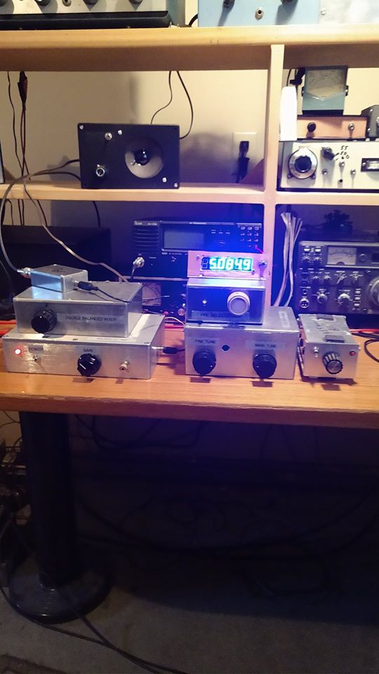
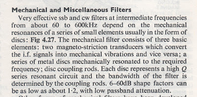
Paul Taylor VK3HN’s magnificent AM receiver was the inspiration for my Quarantine-31 Shortwave Broadcast receiver. Like Paul I decided to make use of ceramic filters at 455 kHz for selectivity. I started with the +/- 3 kHz filters that Paul used, but I found them kind of narrow for SW listening. So I went with some wider ceramic filters that Bruce KK0S had sent me. But I misread the specs that Bruce sent. I thought they were 10 kHz wide filters. I realized later that they were +/- 10 kHz — really twice as wide as I needed. So I went back to Mini-Kits in Australia and got some +/- 6 kHz filters. 12 kc wide should be just about right, I thought.

The bandwidth was right, but I started noticing a problem: I could hear strong SW broadcast stations at two places on my dial. This brought to mind an admonition from R.A Penfold, author of “Short Wave Superhet Receiver Construction” (1991 Babani Publications). He advised keeping a few standard 455 kc IF cans in the circuit because, he warned, the ceramic filters have spurious responses, spurs that the IF cans can help knock down.

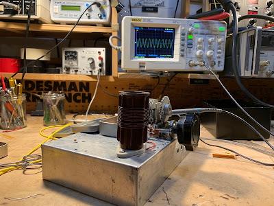
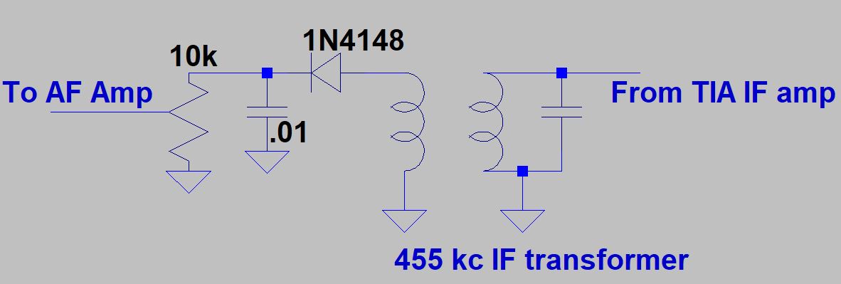
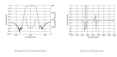
Penfold was right. Look at the filter response curve on the right (above). There is a nasty spur at around 640 kHz. This was the cause of my problem. Here is why:

Suppose I was tuning Radio Marti’s big signal on 9805 kc. My VFO would be running at 9350 kc.
9805-9350=455. Great, but…
With that spur at 640 kc, I could tune down to 9620 kc on my dial. My VFO would be running at 9165 kc.
9805-9165=640. Bad. That 640 kc difference product would make it through to my detector and AF amp. I’d have Radio Marti showing up in two places. I didn’t like this.

I thought about putting a series LC circuit tuned to 640 kc at the output of the ceramic filter. This looked like a possible solution, but on the bench it looked like I would have trouble getting a circuit of sufficiently high Q.

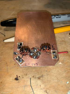
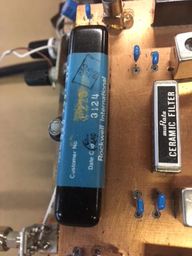
So rummaging around in my junk box I found an old Murata CFM455B filter. This filter is quite broad, but it does not have the spur at 640 kc. I could use it as a kind of roofing filter just ahead of the +/- 6 kHz filter. Putting it there would allow me to avoid having to build additional matching circuits for the 455B filter.

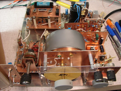
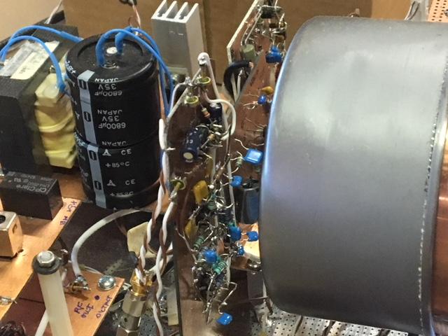
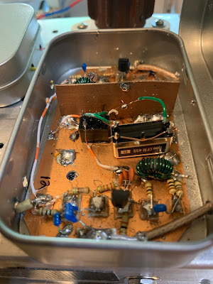
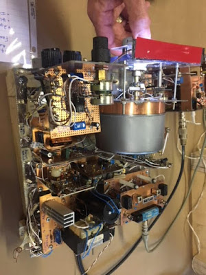
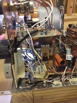
+/-6kc filter upper left, 455B wide filter to the lover right.

I’m happy to report that this fix works. The 6 kc filter provides the needed selectivity, and the broader 455B filter knocks down the 640 kc spur.

Beware the Ceramic Spurs!

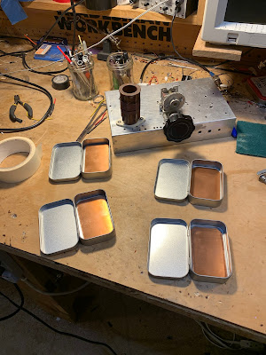
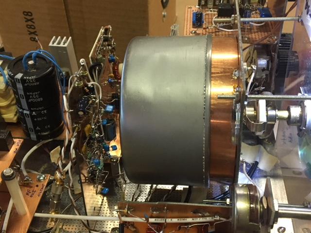
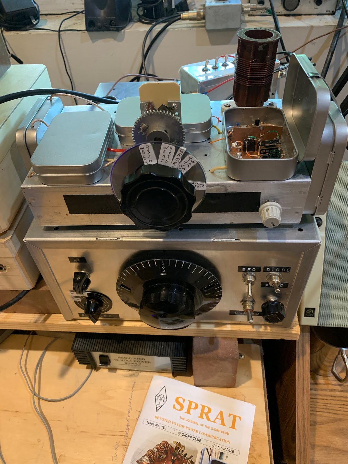
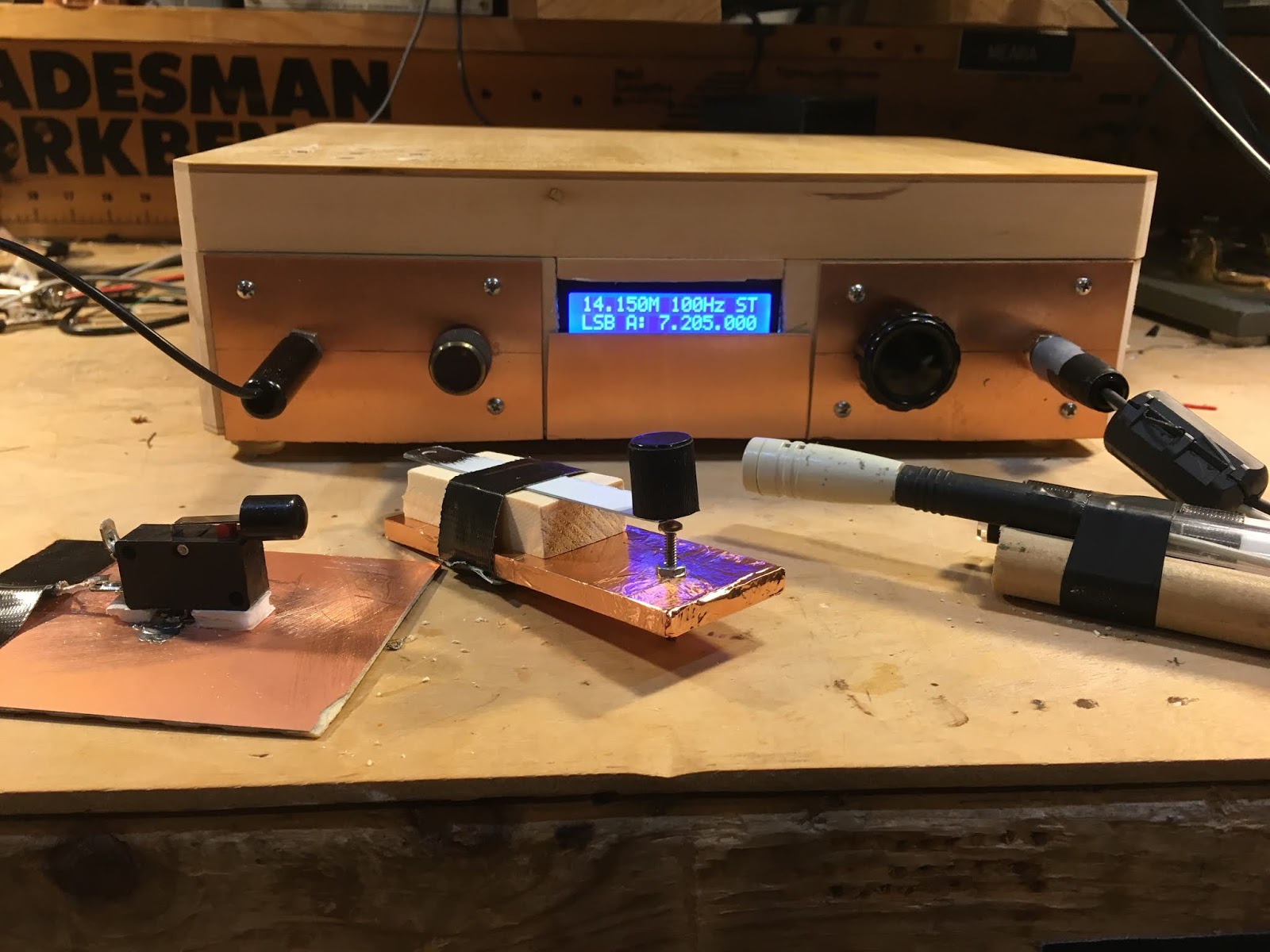
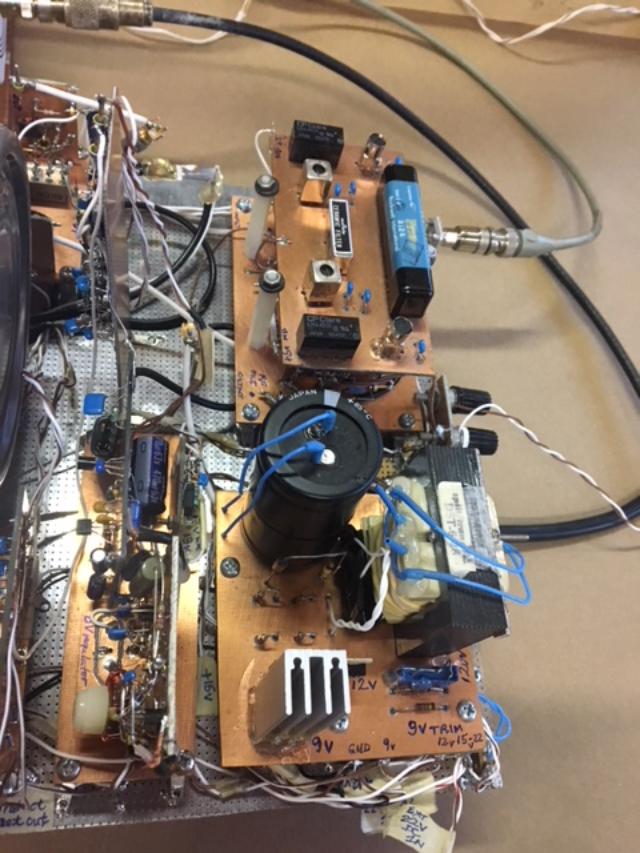
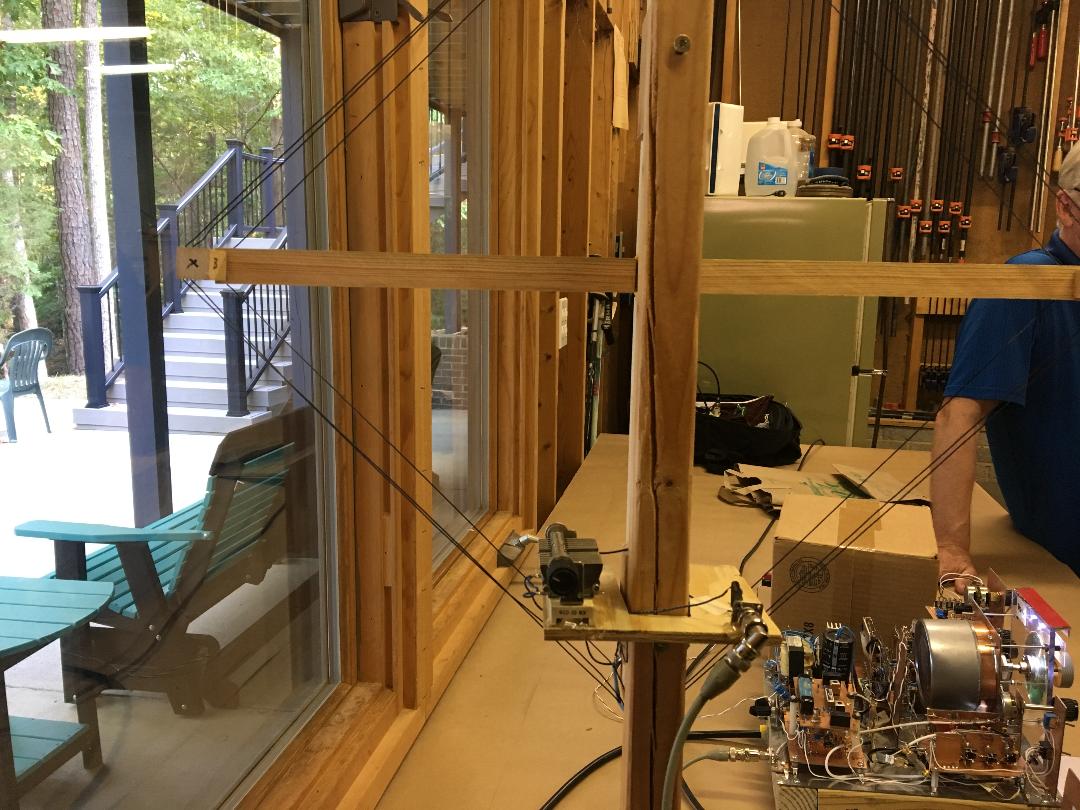
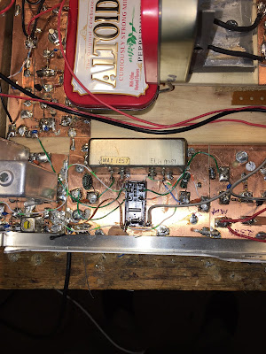
Q-31 with can for first IF amps and filters open

Dilbert, Shep, Dex, Pete, Farhan, and Wes! N2CQR Presentation on Homebrewing to Local Radio Club

Dean KK4DAS asked me to speak to our local radio club, the Vienna Wireless Society. It was a lot of fun. I talked about my evolution as a homebrewer, some of the rigs I made, the moments of joy, and the tales of woe. You can watch the presentation in the video above.

I was really glad to be able to explain in the presentation the importance of people like Pete, Dex, Farhan, Wes, Shep and even Dilbert.

I was also pleased to get into the presentation the N2CQR sign that Peter VK2EMU made for me. Thanks Peter!

Here is the URL to the YouTube video (also above):
https://www.youtube.com/watch?time_continue=3414&v=VHSr-v4QO7Q&feature=emb_logo

And here are the PowerPoint slides I used:
https://viennawireless.net/wp/wp-content/uploads/2020/06/VWS-presentation-Rig-here-is-homebrew.pdf

Idaho Homebrew — Brian KE7LOY

Brian wrote (on Facebook):

This (above) is a general Shortwave Superhet receiver I built over the winter. I chose to go modular so I could interchange some of the modules and make easy repairs and changes to the circuits. I used discreet components and only 2 integrated circuits. I built a Colpitt’s buffered oscillator which is remarkably stable, a Gilbert Cell Double Balanced Mixer, a high pass filter to filter out local AM broadcast station. The IF chain uses an old classic collins 455 khz mechanical filter amplified by a J310 feeding into an MC1350P IC… It’s using 2 germanium diodes as a detector feeding into an LM386 output amp. It’s very, very selective and sensitive. I added a 455 khz BFO (lower right in pic) the other day to tune in SSB and CW. This has been a fun experiment.

Q-31 Quarantine Receiver — All Boxed Up, Almost Done

Almost done. A few odds and ends remain, but now I have all the circuitry in their boxes.

As I was taking my walk the other day I was thinking of how I didn’t have to build a BFO for this superhet. That’s because the signals coming in on this rig bring with them their own BFO signal (the carrier).

Q-31 Quarantine Receiver — +30 db and a Germanium Diode Help a Lot (video)

Today I added two additional stages of IF amplification. This added 30 db to the receiver’s total gain. That helped a lot. I also discovered that Germanium (1N34A) diodes work a LOT better as AM detectors than do silicon diodes. This receiver is starting to sound decent. Currently listening to the VORW program on WRMI Miami.

Quarantine Rig Q-31 — Putting the Stages Together (Most of Them)

I’ve been recording short videos on my progress with the Q-31 Shortwave AM Quarantine Receiver.

Yesterday was a bit of a milestone — I put five of the six sub-assemblies together and did some testing. You can see the video above.

All the other videos are on my YouTube site:

https://www.youtube.com/user/M0HBR

Please subscribe and give me a “thumbs up.”

SITS! Stay in the shack! Flatten the curve. Hang in there. 73 Bill

Videos on the Q-31 Quarantine AM SW Receiver Project (and some pictures)

I’ve been making some short, stage-by-stage videos of my Q-31 receiver project. So far I have seven videos. They are here:

https://www.youtube.com/user/M0HBR/videos

Please subscribe to my YouTube Channel. And give me some “thumbs up” if you like the videos.

Thanks. SITS! FlattenTheCurve! 73

Pads from Pete, toroids from Farhan
The diode ring
Altoids-sized tins will hold the circuit boards
Stay In The Shack — Or in the front yard.


Radio History Question: Why 455 kHz as the IF frequency?

My work on the S-38Es, on the HRO-dial receiver, on the Mate for the Mighty Midget, and on various mechanical filters has caused me to think (once again) about why we ended up with 455 kHz as the IF frequency for so many radios. I’ve heard many explanations for this, but unfortunately I’ve forgotten the explanations and lost the sources. I started digging into this again today. I found the below e-mail from Al N3FRQ on the Boatanchors mailing list (2008).

I contacted Al to find out if he had learned anything else on this topic. He has not. So if anyone out there has answers to Al’s questions, or anyother info that would shed light on why they went with 455, please let us know.

——————————-

Every so often the question comes up: Why are all the IF’s 455 KHz? I’d like to get an article together that solves this riddle while the people who know are still with us. I know parts of the story, but I need help with a couple of issues. There are two major consideration is the choice of the intermediate frequency used in a superheterodyne receiver. The lower the frequency, the easier it is to attain high selectivity. Also, in the early days, before tetrode and pentode tubes, it was easier to achieve a high degree of amplification at lower frequencies. Conversely, a higher IF frequency results in better image rejection. Early superhets had the IF at 100KHz or lower in order to get adequate gain from the available triode tubes. They suffer severely from “two-spot tuning” (images). By the early 1930’s, broadcast set had settled in at 175KHz, and automobile receivers would later adopt 262KHz as a standard. The advent of the short-wave craze, and multi-band broadcast receivers dictated a higher IF frequency to achieve adequate image suppression on the short-wave bands. The broadcast band occupied 550-1500KHz at this time, and the designer encounters sever problems if his radio tunes across it’s own IF. Some shortwave sets used 1600-1700KHz for better image rejection, but one couldn’t go higher if the 160-meter ham band (1800-2000KHZ) was to be covered. Most multi-band receiver settled in near 450KHz, a comfortable distance from the first broadcast channel at 550KHz. Questions: Odd multiples of 5KHz, 455, 465, etc., were usually chosen so that the image of the carrier of a broadcast-band station could be zero-beat with the carrier of the station being tuned to achieve minimal interference. (This assumes 10KHz channel spacing. Did the Europeans (9KHz) do something else?) The Radiotron Designers Handbook, Third Edition, p. 159, states “A frequency of 455 Kc/s is receiving universal acceptance as a standard frequency, and efforts are being made to maintain this frequency free from radio interference.” (1) Do FCC and international frequency allocations reflect this? (2) I’ve heard the term “Clear-Channel IF.” Can anyone cite references? (3) At lease one news group posting claims that broadcast frequencies in a particular market are assigned to prevent strong inter-modulation products from falling near 455KHz. Is this factual? Need reference.” (4) Was this (3) at least part of the reason for “Radio Moving Day” in 1941? See: http://www.dcmemories.com/RadioMovingDay/032341WINXFreqChange.jpg (5) Many National Radio sets used a 456KHz IF’s and I think I remember a 437 somewhere. Why? Are there different considerations for short-wave CW operation? Further input, corrections, and elaborations are greatly appreciated. Scolarly reference will be looked upon with great favor. Regards, Al -- Al Klase - N3FRQ Flemington, NJ http://www.skywaves.ar88.net/ 


Mr. Carlson Restores an All-American Five — Tribal Knowledge! SITS! Flattening the Curve! (video)

It is always a pleasure to see a new video on Mr. Carlson’s awesome YouTube channel, especially in these days of Staying-In-The-Shack (SITS). Obviously Mr. Carlson is doing his bit in this area. FLATTEN THE CURVE! Thanks OM!

My recent bout of S-38E madness has peaked my interest in the All American Five design, so this March 10, 2020 video was especially interesting to me. Mr. Carlson puts out so much great tribal knowledge. I didn’t know about “rounder” resistors. I didn’t know that you have to be careful not to short out (to the IF can case!) the 455 kc transformers. I really like his approach to dial cord restoration.

Mr. Carlson’s discussion of the adjustment of the front end tuner circuit on this broadcast band radio was very interesting. Unlike the S-38 radios, there are no front end coils being switched in as you change bands. In fact, it appears that that big coil/antenna inside the back cardboard piece IS the front end coil. This discussion has caused me to question my front end alignment technique for the S-38E. Did I have an appropriate antenna or antenna substitute across the antenna terminal when I set the peak on the input LC circuit? I will check on this. Hooray! One more thing to do during the COVID-19 SITS period.

UPDATE: I checked on this using the test set up described in an earlier post, but this time with my antennas connected. First with a 40 meter dipole, then with my 130 foot doublet, then with a 50 ohm dummy load I was still able to see the resonance dips at exactly where I wanted them to be.

My favorite bit of Carlsonian wisdom from this video? Mr. C’s confirmation that some hum in All American Five receivers IS NORMAL! (This may be too much for the folks who find normal band noise to be offensive.)

For Inspiration and Education: Dean’s Radio Blog (with video)

Be sure to check out the blog of Dean KK4DAS. He is a new homebrewer who is having great success with one of Pete Juliano’s ingenious SSB designs. Dean has a video of his receiver working — AL FRESCO — as construction on the full transceiver proceeds.

This is amazing. Just a short time ago Dean was taking his first steps as a homebrewer with his version of the Michigan Mighty Mite. He has followed the advice of the Tribal Wizards and has proceeded slowly, step by step, stage by stage, gaining the experience that has allowed him to actually build a superhet receiver and be on the verge of completing a full SSB transceiver.

Lots of inspiration to be found on Dean’s blog. Check it out:

https://kk4das.blogspot.com/2020/03/dean-kk4dass-furlough-40-ssb-rig.html

AM Diode Detector + 41 and 49 meter Shortwave Bands for HRO-dial Receiver (videos)

The COVID-19 emergency is a good time to look around the shack for projects you have been meaning to take on but didn’t have the time for. We have the time for them now!

When I first built my HRO-dial receiver (using an HRO dial given to me by Armand WA1UQO and an enclosure from Tim KI6BGE) my hope was to have the 40 meter ham band and some shortwave broadcast bands. But it didn’t work out that way. I had trouble getting an AM detector to work properly, and I had a hard time getting a sufficiently broad filter to work right. I ended up adjusting the VFO so that the receiver would cover only the 40 meter ham band.

My recent S-38E adventures and a video from VK3HN have alerted me to the nice programming that is now on the shortwave broadcast bands (I really like WRMI’s afternoon rock music program). So I decided to take another shot at getting this receiver to cover SW BC frequencies.

When I built this receiver, I made the front-end bandpass filter tune-able. There is a two section variable cap behind that “Pre-selector” control you see on the front panel. That lets me tune two loosely coupled LC circuits from about 5.5 to about 8 MHz. So without any mods to the front end, I could cover the 49 meter band (5.9 — 6.2 MHz) our 40 meter band, and the 41 meter band (7.2-7.5 MHz)

Here is how I do it:

For 49 meters: I now have the VFO set to run from 6.34 MHz to 7.120 MHz. The IF is .455 Mhz. So to get down to the lowest frequency in the 49 meter band, I tune that front end preselector down to that frequency (variable cap in filter almost fully meshed). Then I take the VFO down to 6.355 Mhz. I take the difference frequency out of the mixer — .455 MHz.

For 40 and 41 meters: I just tune the pre-selector to this range (variable cap about mid-range) and tune the VFO accordingly. For a signal at 7.5 MHz, for example, I put the VFO at 7.045 MHz. 7.5 – 7.045 = .455 Mhz. Note: There is no sideband inversion in this case — this is important because 40 meter SSB is lower sideband. The Kokusai mechanical filter that Pete N6QW gave me is a lower sideband filter. I have my BFO set at the right spot relative to the filter passband for LSB.

As you can see, I just tune to the “image frequencies” with the preselector. This gives me double the frequency coverage.

As for the filters, well Pete’s Kokusai filter works great on 40 SSB. My problem was, ironically, getting a filter that was broad enough to let AM sound good. I concocted a filter using old 455 kc IF cans, but I wasn’t happy with it. Paul VK3HN used a ceramic .455 MHz filter that was 6 kHz wide at 6 db down. I ordered some from Australia. That should have been wide enough for AM, but I had gotten spoiled by the very WIDE bandwidth of my S-38Es (no real filters at all, just the two 455 kc IF cans). At this point The Radio Gods interceded. Bruce KK0S heard me talking about this on the podcast and kindly sent me some 10 kHz .455 kHz filters. Now we’re talking! I put one of them in this receiver and AM started sounding as good as it does in my S-38E. BTW — a look at NA5B’s WebSDR receiver shows that most of the SW broadcast stations are running at 10 kHz wide. See video below:


Finally, I had to get a decent AM detector going. The SBL-1 product detector I have in there works great, but I had tried several AM detectors and none of them worked well for me. This was puzzling — it should be so simple, right? Just a diode. But I would get weak and/or distorted audio. I realized that I really needed was something that looked to the rest of the circuitry like an SBL-1, but with just a diode and an RC filter section instead of the SBL-1’s diode ring. I ended up using a small 455 kc IF transformer that Michael Rainey (AA1TJ) had sent me a long time ago. My detector looks like this:

It works great. During the day I can hear the Toronto CFRX talk-radio station that simulcasts with 1 kW on 6.07 MHz. In the evening I her WBCQ and many other stations on 41 meters (see videos). And of course I am ready to use it for amateur AM signals on the high end of the 40 meter phone band.

There is a lot of soul and friendship in this receiver:
— HRO dial from Armand WA1UQO
— Aluminum box from Tim Sutton KI6BGE
— Mechanical Filter from Pete N6QW
— IF transformer from Michael AA1TJ
— Ceramic filter from Bruce KK0S
— 10k pot in the detector from Thomas KK6AHT
— Inspiration and ideas from Paul VK3HN
— Many parts from Jim…

But you know, I find myself thinking that there are many stations I like on the 39 meter band. I think it might be best to build a separate receiver for those frequencies. Maybe throw in 30 meters. Hmm, let me see what’s in the junk box…

SolderSmoke Podcast #216 Is Available: BITXs, Paesano, Paraset, ET2, Antuino, Mailbag

Bill’s uBITX with HB keys and the mic that used to be the podcast mic!

SolderSmoke Podcast #216 is available

21 December 2019

HAPPY HOLIDAYS TO ALL!

http://soldersmoke.com/soldersmoke216.mp3

Pete’s Bench
Sprat Article
BITX 40 Fun
ZL2BMI Rig
Paraset. Three tubes! Almost an ET-3!

Bill’s Bench
ET-2 Adventure over, Rig on the wall
Final QSO count. 20 3 “random”
Last QSO with AA8OZ
Lessons learned: 100 mW not the problem. Crystal Control cramps your style.
N0WVA regen amazingly effective.
Tried for the Sunrise Net. Walter sent me some crystals.

On to the uBITX.
Accidentally wiped out calibration and BFO settings.
Had to do recalibration and reset BFO.
Learned a lot about the rig.
How they did CW and how they do it now. Shift TX? Or shift RX? Or just shift BFO on RX?
How all the signals end up as upper sideband. Only one BFO freq. Very cool.
TalentCell 12 V Lithium Ion 3 AmpHour battery. Size of a deck of cards.
Inspired by Peregrino — I ordered EFHW Tuner from QRP Guys.
Homebrew Straight Keys

Antuino upgrade
SMT soldering.
Back to Arduino Nano and the IDE.
A very cool tool.
Antuino filter analysis.
Version 6 of uBITX out.

The “Watt Meter” DC power meter. Very useful. 8 bucks. LINK:

https://www.ebay.com/itm/Digital-DC-combo-Meter-LCD-Watt-Power-Volt-Amp-RC-Battery-charging-Analyzer-M/152339793114?fbclid=IwAR0u9SlZi2Dm6zOJyZt4fDTu7w_pjBIEYD_FiNfLymxtQUbMjcNHjfB17P0

SPRAT, balloons and hardcore homebrew hydrogen.

MAILBAG
VK3HN’s AM receiver. I ordered 6kHz 455 kHz filters from Australia.
Dean’s MMM
Peter VK2EMU Hertz not hertz.
Ben KC9DLM LTSpice YouTube Videos
Steve Silverman Electroluminescent Receiver Kit
Lyndon N0LFX back to listening. FB OM
Steve M0KOV built a pill bottle variometer. Did you get the regen going?
Anthony VU3JVX FB HB uBitx.
Allison KB1GMX Great to hear from her

Leif WB9IWT — helped me trouble shoot my uBITX (BFO was low)

Mike EI0CL old buddy from Azores days. Recognized his voice on 20. Great QSO.

VK3HN’s Inspirational AM Receiver (video)

I’m always delighted when I check the SolderSmoke blog and YouTube list (right hand column of the blog) and find a new post from Paul VK3HN. And this morning’s post is especially good.

Paul has built an AM receiver. Above you can see his video. Here is his blog post with details:
https://vk3hn.wordpress.com/2019/12/06/8-band-superhet-am-receiver/

This is the kind of blog post that makes you want to heat up the soldering iron and start searching through the junk box. I’m thinking about putting Paul’s 6 kHz filter in my 40 meter HRO-ish receiver. And I may make use of his AM detector circuit. And maybe I can put that same receiver on 75 and 160… And then there are the SW broadcast bands… See what I mean?

Thanks Paul. 73

W4AMV’s Beautiful Receiver

Hi Guys,

We had our Knightlites annual BBQ this past Saturday. I wanted to share one of the radios from one of my Elmer’s, Alan Victor W4AMV.
Pictured is him standing beside the preselector and receiver.
I hadn’t ever heard a Collins mechanical filter vs Murata crystal filter side by side. The Collins was amazing. Single signal extracted from the band. The rig is line powered with a built in power supply.
There is a note (pictured) that has some specs.
Alan’s work is to be savored, true analog engineering at its best. I wanted to share it with you.

Chris
KD4PBJ

————————————-
FROM W4AMV’S QRZ.COM PAGE:

Here is a receiver that started out as a regen for the grandkids to copy code.
Digging through the junk box un convered parts that I forgot I had. Included a wide and narrow band set of filters. So, the unit wound up as a single conversion superhet. A fun radio to build as well to listen. The wide band filter provides super fidelity on sideband as well uncovers plenty of CW signals within a 10 kHz bandwith of the tuned frequency. A switch to either a 800 Hz audio filter or a 500 Hz CW filter permits focus on a single signal. I was going to package the whole unit, however I was prompted to leave it OPEN to show what makes it tick!

Left side front is the RF preselector, mixer and pre amplifier with RF gain control. The rear double deck card is the IF and selectable wide and narrow band filters. The IF and pin diode IF gain control is bottom deck. The HF VFO is center stage with a 6:1 gear reduction. Right rear is power supply and voltage regulators. The active product detector and a BFO is just to the front of the power supply. The BFO is able to tune product detector output over a full 10 kHz of the IF. And finally the audio filter and 5 watt power amplifier. There is no AGC. Instead it is FUN to control every aspect of gain control of the receiver; RF, IF and audio. Its a fun receiver to operate, dedicated to 40 meters and hopefully will spark the kids!

Going forward a receiveing station is setup to copy code. Although a nice long high wire would be proper, I settled on something a little more compact. A 40 meter small loop, 2 turns, about 18 inches on a side is connected to the preselector thru a pickup wire. This arrangement works quite well. W1AW will knock the speaker off the desk if your not careful. However, rotation of the loop to the E-W knocks down W1AW to a whisper. The pix shows the little 25 W infinity speaker in a 8x8x8 inch cardboard box, works well and the single conversion receiver sporting a new front plexiglass panel is illuminated for evening tuning.
————————————————

Loop antenna used with the receiver

SDR vs. HDR – Is the Superhet Dead?


Pete N6QW had this very interesting video about Software Defined Radio on his blog. Thanks to G3WGV for putting this presentation together.

It is very interesting, but — for me — it is also troubling. I think something important is being missed in this discussion. You have to listen carefully, but if you do the thing being missed becomes apparent.

Like many others, G3WGV asserts that very soon, 100 percent of commercial radios will be SDR. Traditional superhet radios will be a thing of the past.

OK, but I will make a parallel assertion: Looking ahead, I think 100 percent of TRULY homebrewed rigs will be HDR.

Of course, this really just comes down to how you define “homebrew.” I’m a traditionalist here. I think of homebrewing as actually building — from discrete components — all the stages that send or receive radio signals. By my definition, I don’t think you can really “homebrew” an SDR radio. Taking an ADC chip and connecting it to a computer running SDR software is not — by my definition — homebrew. Even if you wrote the software yourself, writing code is not the same as wiring up all the stages that go into a superhet-style transceiver.

There were a few lines in G3WGV’s talk that seemed to confirm this difference: The SDR radio is defined as a “server.” Commercial manufacturers like SDR because they can use the same components that go into cell phones (exactly — and people will soon have the same relationship with these “radios” that we have with their cell phones).

I kind of grimaced when G3WGV described the two sets of users of SDR technology: the “early adopters” who are “technology enthusiasts”, and the “pragmatists” who don’t care what’s in the box — they just want to talk on it. I think “pragmatist” is a nice way of saying “appliance operator.” Even the “early adopters” are pretty far from the world of traditional homebrew. And for me that gets to the point that is being missed in all this — this shift away from hardware is also a shift away from homebrew.

But hey, this is a hobby. To each is own! Have it your way. For myself, I plan to continue with the hardcore, radical fundamentalist, hardware-defined, discrete component, fully analog homebrew radio. This morning I am attempting to stabilize a cap and coil VFO. And I’m liking it. As the world shifts to SDR, I look forward to the appearance on e-Bay of massive quantities of old forsaken HDR rigs. We will buy them for pennies on the dollar and use the parts for new HDR Superhet rigs.

Viva E. Howard Armstrong! Viva!


An Update on Jac’s Homebrew Receiver

About four years ago we posted a report on the FB homebrew receiver of Jac KA1WI Here is the original report:
https://soldersmoke.blogspot.com/2015/09/jacs-homebrew-receiver-video.html

As most of us do, Jac has continued to work on his creation. He sent me an update:

Bill:

Basically I have finished it, from a tentatively working model to a more definitive set. For example there are three IF filters, LSB, USB and CW switched by relays grounding the un-used filters. The AGC was optimized for a good sound. So was the multistage audio circuit, avoiding unnecessary filtering which in my opinion masks the sound of some very good sounding transmissions, not to mention the terrible ones.


The front end works very well, with a SBL-1 DBM terminated with a low noise 2N5109. You notice it when a strong signal is nearly covering the weaker one you are listening to and it remains readable without loosing strength! No many receivers can do that, either because poor front end, noisy LO or bad AGC or all of the three. Not with this receiver!

The BP filter bank is not my design but removed from a German receiver from the early 1970’s I had to align it to specs and it works pretty well, although I would have preferred to use a tunable pre-selector. I am planning another set with three IF 9mHz filters which will include a pre-selector for optimum image rejection. I hope.

In general I am happy with the set, despite the birdies of the DDS, most of them well under the level of most received signals. I wsh I could build a simple PLL to clean up the DSS LO signal. It is worth exploring issue as I see new VCO designs are available. I could try at least one ham band for starters, a PLL covering 350 kHz locked to the DDS, instead of 2-30 mHz covering, should be feasible.

Have more videos of the set I will send to you.

73s de Sac

KA1WI

Note how well you can hear the band’s noise floor when the antenna is reconnected in the third video.

A Homebrew HRO Dial by DL6WD, Homebrew Hero

Take a look at that beautiful rig in the bottom of the cover pictures. (A closer shot appears below.) That is an HRO dial, right? Or is it?

No, it is not. In the picture we see the homebrew receiver designed and built during the 1960s by Rudolf Fishcer, DL6WD. It is magnificent in every respect. Because I have been working with the HRO dial and gearbox given to me by Armand WA1UQO, the tuning dial on this receiver caught my attention.

Here is what DL6WD says about this part of his project: “The main tuning gear was built around a BC-221 tuning capacitor and reduction gear. The counter dial and tuning knob are the result of four weeks of labor, The counter dial reads in tens of kHz, where the main tuning knob has a calibration of 200 Hz per division, from an HRO inspiration.” The counter is in the little window to the upper left of the tuning knob. The window to the upper right is a phase-lock indicator. (See below.)

By the way, by the time DL6WD got finished with this all solid state receiver it weighed in at 52 pounds. Rudolf noted that “excessive shielding pays in electrical performance, but not in weight!”

DL6WD earns the title “Homebrew Hero.”

Switching to a Mechanical Filter from 1967 for my HRO-ish Receiver (with video)

From RSGB Handbook 1982


Having overcome the difficulties with the National NPW Dial and Gearbox, I turned my attention to the 455 kHz filter. I had been using this old Toyo CM – 455 kc filter (Date stamped August 1969). CM stands for “Crystal-Mechanical.” These filters are hybrid with some of the features of a crystal filter and some of the features of a mechanical filter. For more details go here:
https://soldersmoke.blogspot.com/2016/04/the-meaning-of-cm-in-toyo-cm-455-filter.html

I was disappointed by the CM filter. It seemed very lossey, and it just didn’t seem to be of sufficiently high Q — it seemed very broad. I could hear the other side of zero beat. It was barely a “single signal” receiver, and being “single signal” is the whole point of a superhet.

I remembered that Pete Juliano had sent me a Japanese-made 455 kc mechanical filter. Maybe this would do better. Last night I did a quick comparison test and — wow — Pete’s filter was much better. The Fifth Edition of the RSGB Handbook seems to agree with my assessment, noting that mechanical resonator filters were superior to the Crystal Mechanical hybrids (see pages 4.17 and 4.18)

Pete’s filter is from the Kokusai Electric Company. Part# MF 455 ZL. (Date stamped May 1967). “ZL”indicates lower sideband. I checked and indeed the passband goes from just above 452 kc up to about 454.5 kc. This is a 40 meter receiver and SSB on 40 is LSB, so this filter would work perfectly right? Not so fast! Sideband inversion had to be considered.

I was running my VFO from about 7455 to 7755 kHz. This means that the modulated incoming signal would be SUBTRACTED FROM the VFO signal to get to the 455 kHZ IF. And when that knd of subtraction happens, we have sideband inversion. The LSB signal will look like a USB signal when it reaches the filter.

My BFO was running right at 455 kHz, using a ceramic resonator at that frequency. I briefly considered just shifting it down to 452 kHz, but this proved to be difficult. Then I got a better idea.

I could just shift the VFO down to 6545 to 6845 kHz. This would mean that the VFO frequency would be subtracted from the incoming modulated frequency. There would be no sideband inversion. I had been thinking about doing this frequency shift anyway, thinking that VFO stability gets better as you go lower in frequency.

REMEMBER THE RULE: If you are subtracting the modulated (signal) frequency from the frequency of the local oscillator or VFO, only then will you have sideband inversion. See:
https://soldersmoke.blogspot.com/2015/05/sideband-inversion.html

Moving the VFO was easy. I am using a variable capacitor with several variable caps on the same rotor. I just moved from the smallest variable cap to the middle variable cap — this added capacitance to the system and lowered the frequency. I also added three additional turns on the coil. This put me very close to where I needed the frequency to be. I added one additional 9 pf cap and this put the VFO freq right where I wanted it.

I was really glad to include Pete’s filter in this receiver. The mechanical resonator technology fits very well with the very mechanical old-tech theme of this project (it already had a gearbox — a mechanical filter seemed to fit right in). It is a fascinating device — it is almost like having a set of tuning forks all tuned to 455 kc (see above for the RSGB description of how it works). And having it from from Pete adds a TREMENDOUS amount of mojo, juju, and soul to the new machine.

Icing on the cake: As I type this, I am listening to Fred K3ZO converse in Spanish with hams all through South America. Fred preceded me by three decades at the U.S. Embassy in Santo Domingo, but when I got there the local hams were still talking about him — he was much loved and admired by the Dominican hams. TRGHS. See Fred’s story here (scroll down a bit): http://www.gadgeteer.us/DRDISP.HTM