I was very pleased to read that Chuck Penson WA7ZZE was publishing a book about Heathkit’s amateur radio products. His book is a really great guide, providing a lot of fascinating information, stuff that even those of us who have spent decades with pieces of Heath gear didn’t know. For example, I never knew that an after-market dial had been available for the HW-101. And I didn’t know that the Indian names used for many of the Heath rigs (Comanche, Apache, etc.) resulted from a suggestion from Roger Mace’s wife, who was Native American.
Chuck’s book arrived just as I was putting my DX-40 novice transmitter back on the air after almost 50 years. TRGHS. Who knew that there were TWO versions of the DX-40? I didn’t, but Chuck did, and his book explained how to spot the difference (flashlight through the side vents — I have the very slightly more modern version).
When I opened the book for my first peek inside, the page opened to the QF-1 Q multiplier. I immediately felt guilty about having brutally cannibalized several (well maybe more than several) of these things. But right there in the text Chuck repeats my justification for the carnage: He notes that the tuning cap has a nice 14:1 turns ratio. Exactly. How could I NOT pull those beautiful variable caps out of that old regen device, for re-use in superhet receivers and BITX transceivers?
This is a wonderful book that belongs in the workshop libraries of all those who have used and loved Heathkits over the years.
I’ve been hanging out on 17 meters with my homebrew VXO-controlled BITX transceiver. The antenna is my 75 meter doublet fed with window line through a homebrew tuner made from dead ( I swear) DX-40s and DX-60s. I can tune it up just fine on 17 meters, but I realize I probably have lots of nulls and lobes in the radiation pattern. Apparently one of the lobes is over my old stomping grounds in Panama. Almost everyday I talk to either HP9SAM or HP3SS.
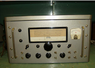
Robby, HP3SS, is using SDR gear now, but he was a real homebrewer back in the day. Years ago he built an HBR-13C receiver. That’s quite an achievement.
Robby — formerly VY2SS — told me that he sold his HBR-13C to none other than Joe Walsh, the rockstar from The Eagles. FB.
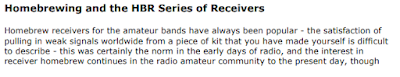
As I was talking to Robby yesterday, I came across this wonderful web page about the receiver:
Robby told me that his receiver looked almost exactly like the one on the SPARC site, but he didn’t recognize the small box with what looked like a speaker on the chassis. I told him that my guess was that this was a crystal calibrator in an oven.
I also told Robby that I feel an affinity with the HBR project, not just because I like homebrew superhets, but also because my call in the UK was M0HBR.
There are some great quotes in the SPARC pdf:
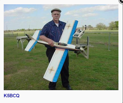
The SPARC page led me to the amazing website of Kees K5BCQ:
This was a receiver built around SBL-1 mixers and 10.7 MHz filters salvaged from an old satellite receiver. It was also the first radio receiver project undertaken by Tom. His use of FPGA technology is especially interesting.
We asked Tom for more info and he kindly provided it:
Tom also sent me Firmware sourcecode that may be reusable for STM8 users, and the FPGA design file (for Quartus users). If anyone has a GitHub or similar site that can host these files, please let me know and we will send them to you.
Rob Sherwood NC0B is one of the real authorities on receiver performance. Many of us have relied on his ratings of commercial receivers for many years. His recent presentation to the Madison DX Club has a lot of really interesting information. There is also, I think, some stuff that homebrewers will find distressing.
Just some things that I noticed:
— Rob mentioned a move back to 9 MHz IF filters and a move away from dual-conversion rigs with a high IF. He also mentioned the combination of a 9 MHz IF and a 5 MHz VFO as a way of easily getting on both 75 and 20 meters.
— Rob discussed phase noise from synthesizers, a topic we discussed at length (some would say ad nauseum!) a year or so ago.
— Rob really praised the “Pure Signal” system of one of the SDR manufacturers. He showed the completely rectangular waterfall display of a Pure Signal transmitter. I’m afraid that simple crystal rigs might never live up to this standard. An embrace of this high standard could discourage the construction of simpler, HDR rigs. We should not let the perfect be the enemy of the good!
— We often hear SSB ops complaining that some other SSB op is “splattering all over the band.” It often turns out that what is really happening is that a clean SSB signal is just overloading the receiver of an operator who does not know how to turn off his pre-amp or turn on an attenuator. Rob shows us how to really know if the problem is in fact at the other end: He looks at key clicks from two different CW signals on 160 meters. Both are at roughly the same level in his receiver But one is clicking all over the place while the other is not. With this kind of comparative info, we can be sure that the problem is the transmitting station’s fault.
— In discussing when to turn on the pre-amp (or the attenuator) Rob revives the old practice of just listening to the band noise. If you can hear the band noise when you switch from dummy load to receive antenna, you have enough RF gain. Adding more will only make things worse.
— There was an interesting question about how to evaluate the performance of receivers when there are many signals inside the receiver’s passband. This is the case with FT-8. Rob said this situation needs more research.
I don’t mean to be critical here — Rob is the guy who evaluated commercial rigs. And he is a contester. So his presentation is, of necessity, going to have a very “appliance operator” orientation. There seems to be an assumption that the only “rigs” that modern hams can use are commercial products. At one point Rob admits that most hams just can’t repair these rigs. There is much for homebrewers to learn from experts like Rob, but presentations like this also remind us of what a tiny minority we really are, and how most hams have moved completely away from the old ham tradition of building our own rigs.
Thanks to Rob Sherwood and the Madison DX Club. And thanks to EI7GL for alerting us to this important presentation.
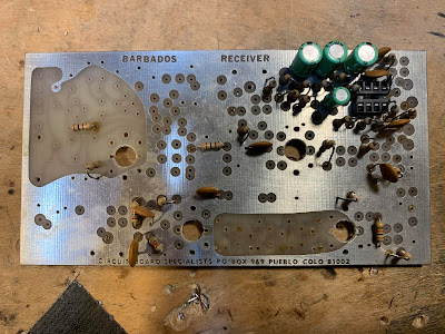
Better than anyone else ever has, Michael Hopkins, in his fictional series about Frank Jones and the Five Meter Liberation Army, captures the spirit of homebrew radio. There is just so much of us in those articles. I read them some 20 years ago when they first came out; reading them again recently I appreciated them even more.
Frank was a bit of a curmudgeon: There are jabs at the appliance operators, Hiram Percy Maxim, hamfests, SSB, the Collins collectors, the QRP movement, and even Electric Radio magazine. Howard Armstrong makes an appearance, as do Carl and Jerry. It all made me want to put a five pin SAW filter on my lapel.
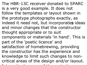
As I read, I thought about what a great writer Michael was. When I Googled him, a few of the results led me back to my own book. I’d forgotten that Michael was in there, but he is. On one page he advises me how to power my Mate for the Mighty Midget receiver without using a power transformer (a very Frank Jones approach). On another page I note that Michael had sent me a kit for the Doug DeMaw “Barbados Receiver.” Wow, that was my first Superhet. (I also have one that was built by Dale Parfitt.) Most of the parts were put to use in other projects. But I still have the board (see above). Reminded that it came from Michael, I will now have to complete the construction.
Below is a nice article about Michael that appeared in the Flying Pigs newsletter. (Click on the images for an easier read.)
This receiver required almost no coaxing or tweaking, probably because I had been so careful about testing and measuring each of the stages.
I have been pleasantly surprised at how well the receiver works without an RF amplifier ahead of the first mixer. But I need to know how much AF gain I have in order to understand how/why the entire receiver works so well. I think I have about 35 db of gain (combined) through the two TIAs and the crystal filter. That would mean that all of the remaining gain is provided by the AF amplifiers (with some loss in the product detector). I haven’t really measured the gain of the AF preamp/LM386 combo, and I had some trouble measuring the input impedance of the pre-amp with the NanoVNA.
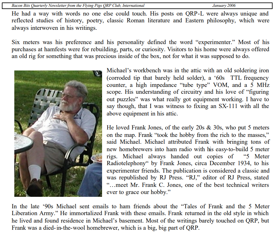
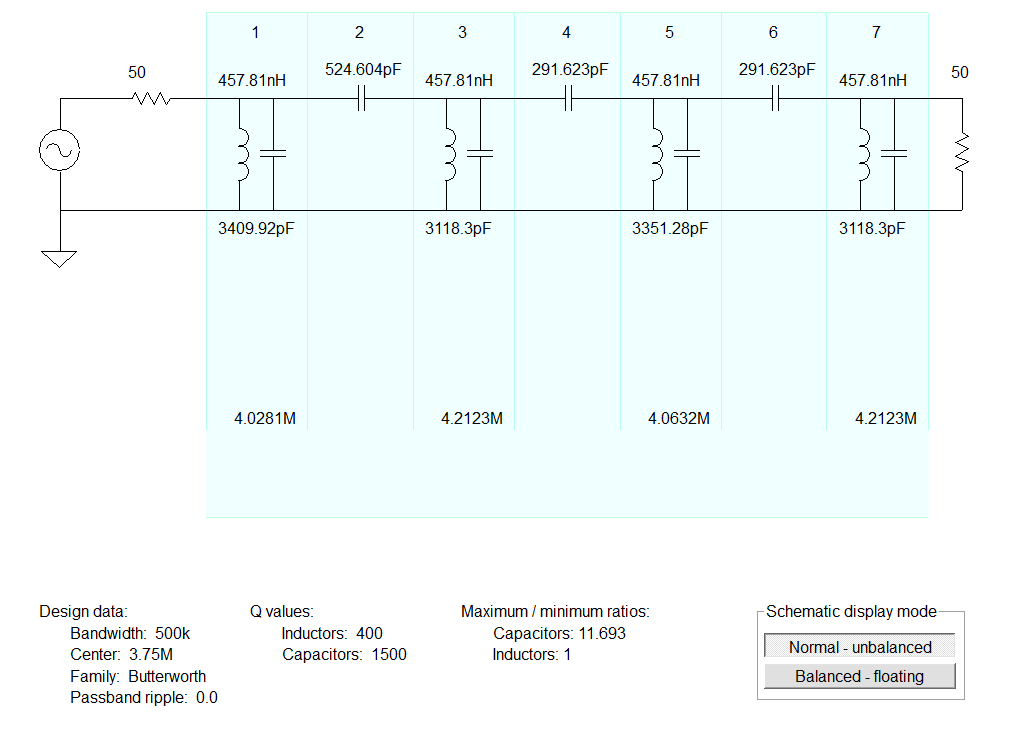
The 75 meter LC filter to the left of the VFO is actually a bandpass filter, not the lowpass filter. And what I call “the mixer” to the right of the VFO is really the Product Detector/BFO.
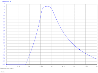
For the 75 meter bandpass filter, I used the ELSIE program.
75 meter Bandpass Filter designed in Elsie. 10 turns on a T50-2 toroid yield .46uH.
Here’s the plot from Elsie on the 75 meter BP filter.
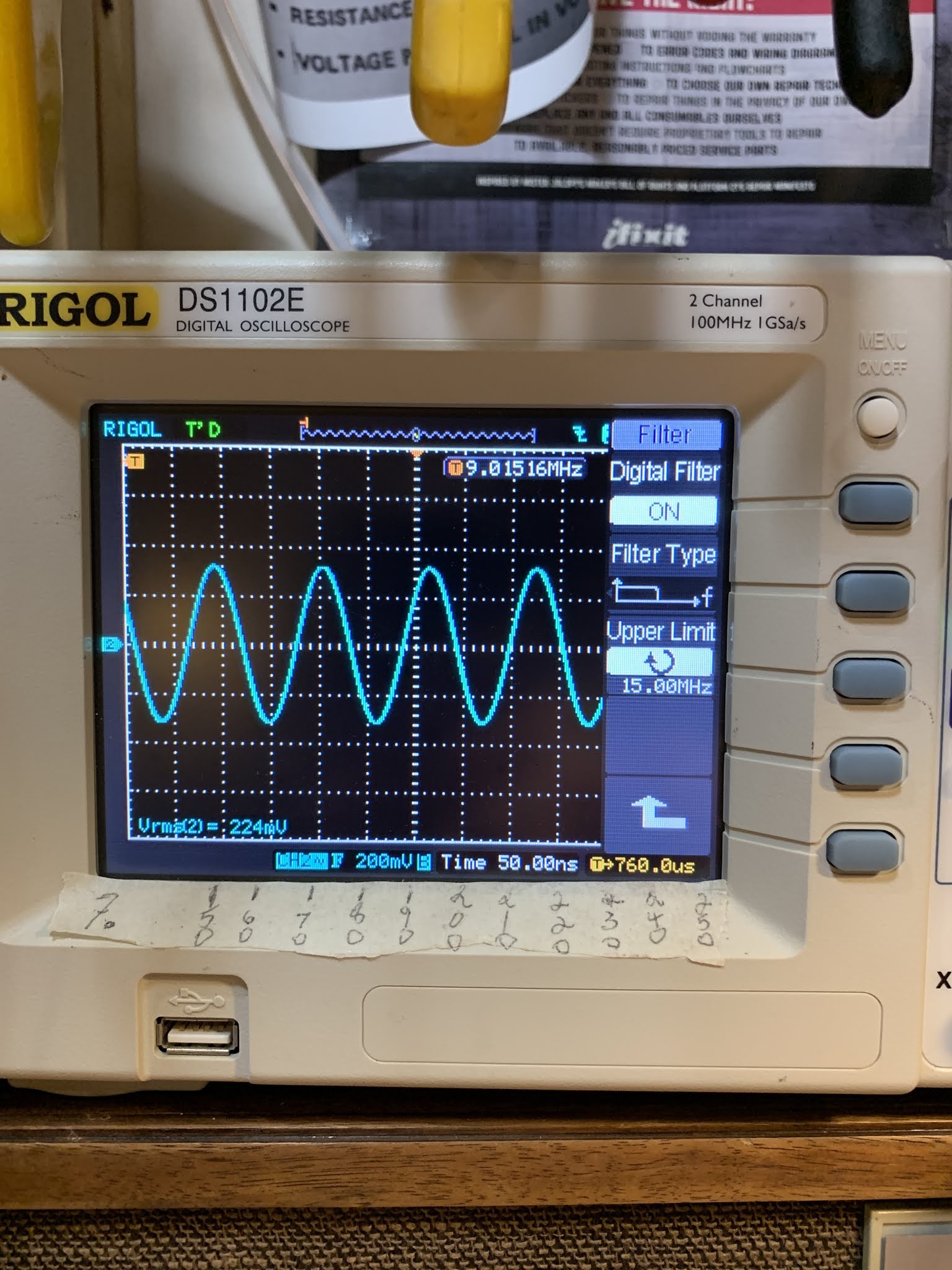
Alan W2AEW asked for a picture of the VFO output.
On this shot I had the probe between theVFO and the
outboard booster amp that I built to bring it to 7dbm.
I am happy to report great progress on the Mythbuster project. I have the receiver working on both 75/80 and 20 meters. And it in fact inverts the 75 meter LSB signals, turning them into 5.2 MHz USB signals for passage through my 5.2 MHz USB filter/BFO combo. No switching or shifting of the BFO is needed.
I am following Farhan’s BITX20 advice — I have paused in the construction and am enjoying the receiver that I have built. I’ll build the transmit circuitry later.
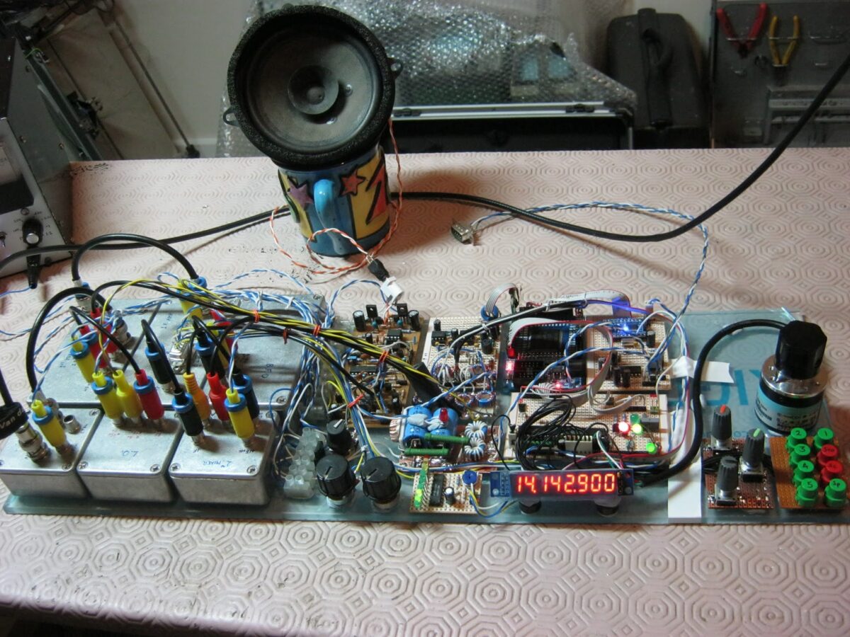
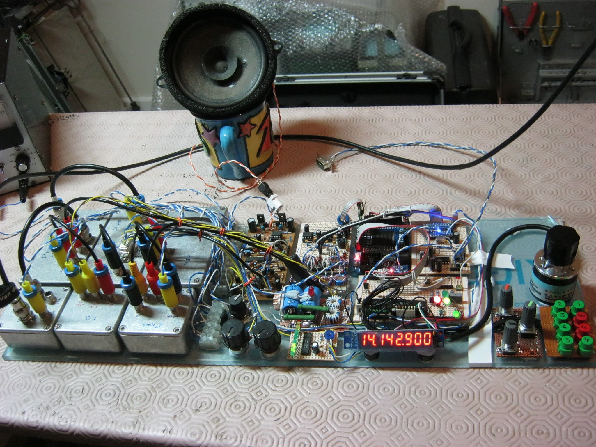
Inspired by Frank Jones (you really should be reading the FMLA articles) I have this rig prototyped “Al Fresco” on a pine board that I found discarded on a neighbors front stoop.
There is no RF amplifier in this rig. Following the advice of multiple receiver gurus, I ran the BP filters right into the ADE-1 diode ring mixer. I have the TIA amps set at about 24 dbm. There is a lot of audio gain from the LM386 and the audio pre-amp. This seems to be enough, even on 20. I hear the band noise when I connect the antenna on both 75 and 20.
Here is the first video in the series. I’m posting them first on Patreon, then, a few days later, here and on the YouTube channel.
Wow, this is really an amazing project. It is so good that I’d like to believe that it is really “all our fault,” but the credit obviously goes to Tom, the very intrepid builder. In a more just world, Tom would be given a ham radio license solely on the basis of this project. Great work Tom. We look forward to more Solder Defined Radios from your workbench.
Dear Bill and Pete,
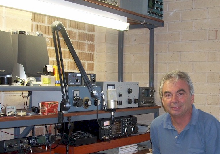
I stumbled across your podcast a few years ago. I had no interest in amateur radio, I was just looking for an electronics podcast that actually discussed electronics (naming no names here, obviously). Well, the inevitable happened, and some of your enthusiasm rubbed off on me. I now find myself humbly enclosing a photograph of my first homebrew receiver for 20m.
The project was one of those “spontaneous construction” affairs, triggered mainly by breaking up an old satellite receiver (I’ve honestly no idea what it was for) which yielded up several SBL1s and a 10.7MHz crystal filter – these form the key elements of the new receiver. It’s a full SDR (solder defined radio) of a conventional single-conversion superhet arrangement. The chief abnormality is that, because the IF filter is as wide as the proverbial barn door, I only use “one edge” – the other half of the passband being provided after conversion to baseband. Of course, that only works if there are no massively strong stations in the 6kHz above where you’re listening, but it seems to be ok most of the time. It does give me the advantage of being able to adjust the lowpass point of the AF signal by adjusting the BFO, which is nice.
You’ll notice there’s a lot of “digital nonsense” in the picture, for what’s supposed to be an analogue radio. This “supervises” the two VCOs: There is an FPGA which implements a pair of frequency meters and an STM8 microcontroller which is in charge of adjusting the control voltages to keep the VCOs where they should be. It’s all slightly roundabout because I wasn’t clever enough to design a PLL which would give the required resolution (and I wanted to do something “more RF” than throw down a DDS chip). This gives me stability as well as fancy bells and whistles, like numeric readout, tuning info via RS232, automatic scanning and frequency presets. I’ve used a (cheap) industrial/automation style encoder for the tuning control, which gives a lovely analogue-like action.
Despite my best efforts (and a lot of ferrite in strategic places) I wasn’t able to keep all the digital spurs out of the receiver. So I devised a dirty hack by way of a button which will shift the MCU an DAC clocks to a different frequency. I can’t remove the spurs, but now I can hide them!
So far I’ve played with a “long” wire and a little shielded loop for antennas – I’m in a first floor flat with a lot of noise locally, and my plan is to get a loop up in the loft space (so the next project might be a rotator!). I fancy maybe seeing if I’ve space for an inverted V, too.
You’ll notice that I’ve not attempted a transmitter. That, of course, is because I’m not yet a licenced ham! However, I’m intending to put that right sometime later in the year. Then – who knows – I might make a contact!
Thanks for reading (although really it’s the least you could do given that this *is* all your fault) and I hope you’ve enjoyed hearing about all the trouble your little podcast has got me into.
Keep up the good work gentlemen, 73 from South-West England. Tom.
PS. I also have a copy of Bill’s book, which I’ve very much enjoyed.
My radio emotions were swinging wildly as I watched this video.
Readers may recall that over the years I have brutally cannibalized several QF-1s. I was enticed into doing this precisely by the tuning cap that the videographer so alluringly describes. It has a built in 7:1 reduction drive! How could I resist? These wonderful caps live on in several of my homebrew rigs.
I also put the conveniently sized metal cabinets to good use — one holds frequency counters for my AM station, the other houses an Si5351 VFO/BFO that can be used with many rigs.
After extracting the cap and putting the boxes to good use, I was left with the remainder of the circuitry. I recently put even this stuff to use by using the coils to make a triple LC circuit filter for 455 kHz. This may someday be used in a receiver. So you see, I’ve not been wasteful.
And the thing only cost 9 bucks back in the day… So I didn’t really do anything bad. And besides, adding a regen circuit to a superhet is kind of backwards, right?
But then the video producer started talking about how nice his QF-1 looks, even after more than 60 years. And about how much it improved the performance of his AR-1. And then, the kicker: He said the QF-1s are now “relatively rare.”
I hang my head in shame. I am a serial QF-1 killer. And I don’t know if I can stop.
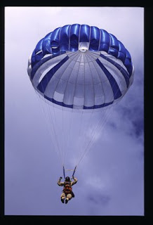
We’ve had some pretty amazing contact with Kevin AA7YQ over the years. Kevin and I originally bonded due to our common experience with parachutes (he was smoke-jumper, I jumped while in the army). Kevin once used a parachute to insulate a QRSS beacon. And one day, while thinking about SolderSmoke during a drive through Montana, Kevin turned on his rig only to hear… ME! He caught one of my infrequent CW contacts. TRGHS.
Now we hear that OM Kevin may be poised to end the HDR-SDR civil war that has for so long been dividing our great podcast. Can Kevin’s new rig heal our wounds and allow us to enjoy the beauty of SDR waterfalls while not forsaking the joy of hardware defined rigs? Kevin will soon launch a blog describing his effort at rig-building. See below for a preview. Stay tuned.
Kevin wrote:
I am currently working on a new rig design. It is a hybrid HDR(Hardware defined)/SDR radio that incorporates some classic superhet design along with some of the more useful features of SDR. I have found that pure SDR is really not that enjoyable for me. I love using GNU radio to mock up and test design concepts, but SDR basically dilutes the “magic” of radio to nothing more than software and touchscreens, stuff we use every day all day. Its not the Ham Radio I grew up with as a kid and was fascinated by. On the other hand, I have always fought temperature drift, large variable capacitors minimal tuning range, and associated with classic VFO and VXO designs. In fact, in 1997, for my senior capstone design in EE at Montana State University, I designed a 20m superhet that used a DDS LO. At the time DDS was cutting edge technology I used an AD7008JP50. I had to beg and plead with ADI to get a couple samples for my design, since they exceeded my self-funded college student project budget. 😊 But that’s another story. SDR has made me grow extremely fond of the waterfall display. I love having the visual “situational awareness” of what is going on in a moderate bandwidth outside of the spot I am tuned to. I also am a big fan of digital filtering and modification-ability that comes with boot-loadable microcontroller designs. So this design includes most of the real highlights of SDR but does not take the fun out of designing, building, and operating a HDR.
Anyhow, this design is a big goal of mine to complete and build in 2021. I am not retired yet so I still have to balance, work, family, and tinkering time, but I am very excited about this project. I have “noodled” this design to the point of what I have achieved full-on “analysis paralysis”. That is, I keep designing and redesigning, optimizing, and figuring to the point where after months of thought, I have nothing to show for it 😊. So my New Years goal for 2021 is to make “good enough” rather than “perfect” design decisions and move forward. I will keep you posted on the design and possibly start a blog so I can get some peer review input from the greater RF Design/Homebrew community on my project. I’ll keep you informed on my progress.
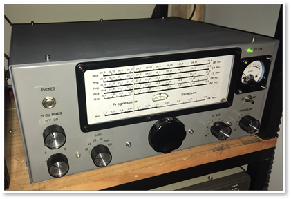
Google led me to VK2FC’s amazing site. I was digging up info on product detectors and I landed on Glen’s description of his version of the W7ZOI Progressive Receiver. Glen’s website provides a very detailed, board-by-board description of how to build this great receiver. I now want to build one.
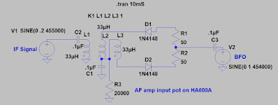
Diode product detector on the left, BFO amp in the right
As noted in an earlier blog post, I didn’t like the sound of SSB and CW when using the product detector in my Lafayette HA-600A. It just did not sound right. The receiver sounded fine on AM with the diode detector. But when I switched in the product detector, it sounded bad. The BFO was fine. The problem was there even when I used an external BFO. And SSB sounded great when I just coupled some BFO energy into the IF chain and used the diode detector to listen to SSB. My suspicions were focusing on the very simple BJT product detector.
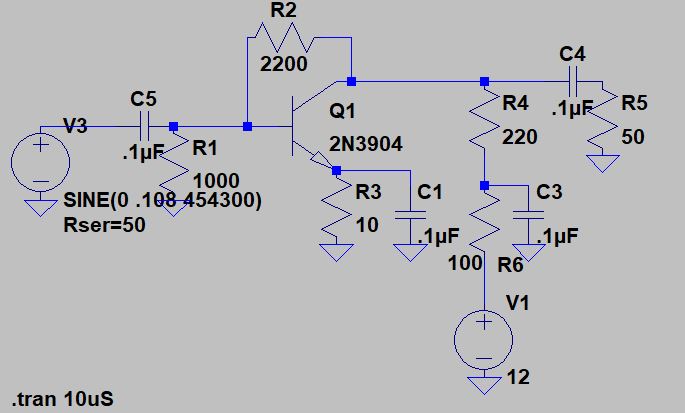
Steve N8NM built the HA-600A product detector both in LTSpice and in the real world. It worked fine in both versions. Steve even put the product detector into his S-38 receiver — he reported it worked well there.
I too built the thing in LTSpice. Then I went and rebuilt the circuit on a piece of PC board. I connected the new circuit to the HA-600A, using my external FeelTech sig generator as the BFO. IT STILL SOUNDED BAD ON SSB.
At this point I started Googling through the literature. I found a promising article by Robert Sherwood in December 1977 issue of Ham Radio magazine entitled “Present Day Receivers — Problems and Cures.” Sherwood wrote:
“Another area that could use additional work is the product detector. As the name implies, its output should be the product of the two input signals. If BFO injection is removed, output should go to zero. If this is not the case, as in the Heath HW series, envelope detection is also occurring, which causes audio distortion.”
I checked my circuit. When I removed the BFO signal from the product detector, envelope detection continued. In fact, with the receiver in SSB mode, and with the BFO disconnected, I could listen to the music of WRMI shortwave. It seemed that Sherwood was explaining well the problem I was having: Simultaneous envelope and product detection was making SSB sound very bad in my receiver. What I was hearing just seemed to SOUND like what you’d get with a mixture of product and envelope detection: “scratchy” sounding SSB. This also seemed to explain why SSB would sound fine when using the diode detector with loosely coupled BFO energy — in that case it would be envelope detection only, with no ugly mixture of both kinds of detection.
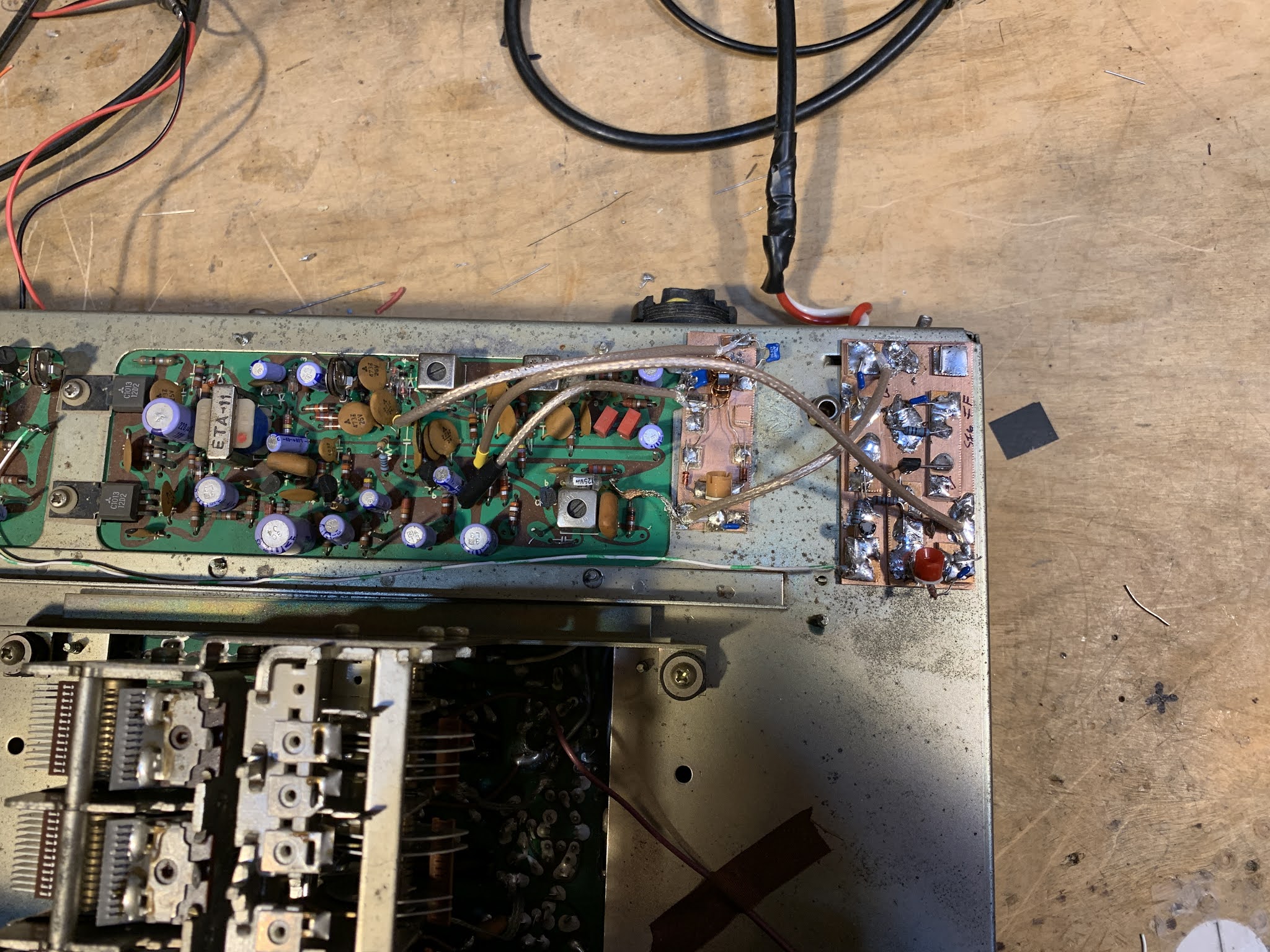
So I built a better detector. I had had great luck with the two diode one trifilar transformer singly balanced design used by both Doug DeMaw and Ashhar Farhan. I built the circuit using one of the trifilar toroids given to me by Farhan, and connected it in place of the original BJT product detector. With the FeelTech Sig Gen as BFO, I got good results — most of the signal disappeared with I disconnected the BFO. Looking at the circuit, I realized that I was balancing out not the IF signal but instead the BFO signal. To minimize envelope detection I needed to put the IF signal on the balanced input of the product detector (to L1 in the diagram above). When I did this, envelope detection seemed to disappear completely and the receiver went silent when I disconnected the BFO.
Finally, I needed to find a way to use the BFO in the HA-600A with the new product detector. Obviously I needed more BFO signal — I needed about 7 dbm, enough to turn on the diodes. I converted the outboard product detector board into a simple amplifier and put it between the HA-600A BFO and the BFO input port of the new product detector. This works fine.
A few issues remain:
1) The output from the HA-600A BFO through the above BFO amp (and across the 50 ohm resistor) is NOT a pretty 455 kc sine wave. But the peaks of the distorted wave appear to be enough to turn on the diodes, and when I look at the voltages across each diode (on my two channel ‘scope) I see mirror images — one is on when the other is off. Is this good enough?
2) Moving the BFO input from L1 to the junction of the two 50 ohm resistors (that is actually a 100 ohm pot) has big implications for how this mixer works. With the BFO energy going through the toroid, BOTH diodes are being alternately turned on and turned off. But both are on, and then BOTH are off. With the BFO energy going in through the other side, one diode turns on when the other is off. I think the mixing result is the same, with AF coming out of the output port, but the way the mixer works in this configuration is very different. Does this sound right?
You have long been one of the leading gurus on DSB. I remember absorbing all the info I could from your website when I was getting started in DSB back in 2001.
It’s great that you found the article about DSB with inverted audio. It would be very cool to build a transmitter with the inverted audio, then confirm that it could be received with a direct conversion receiver without distortion.
The incompatibility of DSB TXs and DC RXs seems like a very cruel trick of nature. There are only a few people in the world who think about this, and most of them are in the comments section of your YouTube video! An elite group indeed.
Back in 2015 your review of a DSB rig got me thinking about this incompatibility: https://soldersmoke.blogspot.com/2015/07/peter-parker-reviews-dsb-kit-and.html
It is easy to see how a slight frequency difference between TX VFO and RX VFO would cause a lot of distortion, but similar distortion would be caused by a phase difference between the two VFOs. AM SW Broadcast receivers try to minimize the effects of fading by using an internal oscillator to replace the wavering carrier — but they have to have it exactly on frequency and locked in phase with the distant station’s carrier. I have a little Sony portable that has this “synchronous detection” circuitry. It is a complicated task and I don’t think you could do it with the highly suppressed carriers of our rigs. Inverted sidebands to the rescue!
Thanks for the great video and all the tribal knowledge.
I’ve been having a lot of fun with the Lafayette HA-600A receiver that I picked up earlier this month. Adding to the mirth, I noticed that on SSB, the signals sound a bit scratchy, a bit distorted, not-quite-right. (I’m not being facetious; this is an interesting problem and it might give me a chance to actually improve a piece of gear that I — as a teenager — had been afraid to work on.)
Before digging into the circuitry, I engaged in some front panel troubleshooting: I switched to AM and tuned in a strong local AM broadcast signal. It sounded great — it had no sign of the distortion I was hearing on SSB. This was an important hint — the only difference between the circuitry used on AM and the circuitry used on SSB is the detector and the BFO. In the AM mode a simple diode detector is used. In SSB a product detector and BFO is used. The BFO sounded fine and looked good on the scope. This caused me to focus on the product detector as the culprit.
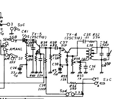
Check out the schematic above. Tr-5 is the product detector. It is really, really simple. (See Einstein quote below.) It is a single-transistor mixer with BFO energy going into the base and IF energy going into the emitter. Output is taken from the collector and sent to the audio amplifiers. (A complete schematic for the receiver can be seen here: https://nvhrbiblio.nl/schema/Lafayette_HA600A.pdf )
I had never before seen a product detector like this. One such detector is described in Experimental Methods for RF Design (page 5.3) but the authors devoted just one paragraph to the circuity, noting that, “We have not performed careful measurement on this mixer.” The lack of enthusiasm is palpable, and probably justified.
To test my suspicion that the product detector is the problem, I set up a little experiment. I loosely coupled the output of a signal generator to the IF circuitry of the HA-600A. I put the sign gen exactly on the frequency of the BFO. Then, I switched the receiver to AM, turning off the BFO and putting the AM diode detector to work. I was able to tune in the SSB signals without the kind of distortion I had heard when using the product detector.
So what do you folks think? Is the product detector the culprit? Or could the problem be in the AGC? Should I start plotting a change in the detector circuitry? Might a diode ring work better?
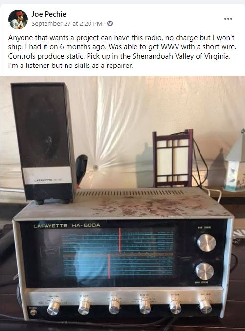
So on September 27,2020, I was sitting quietly in my shack, perusing the postings on various radio-related Facebook groups, when suddenly I saw it: my very first shortwave receiver, the magic box that had put me firmly on the path to amateur radio, the Lafayette HA-600A. Joe, the owner, was offering it FREE to anyone willing to pick it up at his home in Virginia’s Shenandoah Valley. Holy Cow! I was scheduled to drive through that very valley later that week. A message was sent and the deal was done. CLEARLY THE RADIO GODS HAD SPOKEN (TRGHS).
Sure, the cabinet looked a bit rough, but I had high hopes for this receiver. A while back I had — in a similar fit of nostalgia — bought what had been advertised as a Lafayette HA-600A on e-bay. But it turned out to be a Lafayette HA-600 (no A). I immediately noticed a big difference in performance. That was NOT the radio that I remembered, not the receiver that had carried HCJB and Radio Moscow to me. Joe was clearly offering the A model.
A few days later I was in Joe’s front yard for the hand-off, and a few days after that the HA-600A was on my bench.
I quickly realized how little I knew about this receiver. Mine was a Christmas gift, probably in 1973. (A few days ago I talked to my mom and thanked her for driving all the way to New Jersey to get this receiver for me.) I was so taken with this thing that I feared doing something — anything — that might mess it up. I lived in fear, for example, that some sort of freak mid-winter lightning bolt might destroy it. I covered it with a towel each night lest dust encumber its “jeweled movements.” Obviously I was just not inclined to crack open the case and have a look around. So I didn’t, and the receiver remained pretty much an appliance for all the time I owned it. (I eventually sold it on consignment at Electronics 59 in Spring Valley, New York. The proceeds probably went toward the purchase of a much better Drake 2-B receiver.)
I downloaded the manual and familiarized myself with the receiver: It is a single conversion superhet with a 455 kc IF. It is all solid state with no ICs — all discrete transistors and diodes. The manual claims it has a mechanical filter. I kind of hoped for something like a Kokusai mechanical filter, but it turns out that the filter was really ceramic, not mechanical. Bummer.
The thing fired up right away and was inhaling on the correct frequencies. I noticed immediately that (as Joe had indicated) some of the controls were scratchy. I also noticed that the ganged band selection switch was intermittent and required some jiggling to get it to work properly. A few squirts of Deoxit D5 took care of all that. There seemed to be a bit of dirt in the main tuning capacitor, but I think I managed to blow that out using a can of Dust-off. I was quickly listening to the SW broadcast stations, and to radio amateurs on 75 and 40 meters.
Out of curiosity, I compared schematics of the HA-600 and the HA-600A. There was indeed a big difference — the front end of the 600 lacks a lot of the RFA amplification circuitry of the A model. That’s probably why is seemed so deaf and so different from what I remembered of the A model.
There is really not a lot to do on this receiver. I’ll get some paint to fix up the top cover. I may check the alignment. But this single conversion receiver is so simple that alignment would be quite easy. In many ways this receiver seems like a solid state analog to the Hammarlund HQ-100, but without the clock, and without the regeneration circuitry. The dial lacks the exotic station locations (Java!) that make many of the older receivers so much fun. I guess this is an indication that this receiver was aimed more at amateur radio operators than at shortwave listeners ( I was both). I wonder how the ham band-only HA-800 compares to the HA-600A?
I could pair this receiver up with a DX-40 transmitter that I have on the shelf and I’d be most of the way toward re-creating my novice station. Anyone have a Globe VFO Deluxe? That would complete the setup.
Thanks very much to shortwave listener Joe Pechie for providing what is, for me, a very meaningful piece of gear.
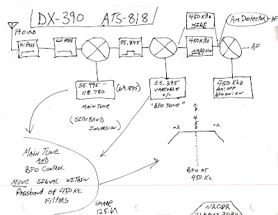
I’m more of a single conversion guy myself, but in working with the DX-390 I came to appreciate the benefits (especially regarding image rejection) of the double conversion technique. While working on the DX-390, I discovered that the BFO control on the front panel DOES NOT change the BFO frequency. It was fun to try to figure out why the designers did it this way. It does make sense once you consider the limitation imposed by that PLL main tuning oscillator that only moves in 1 kHz steps. I hope the video explains things. Here is the drawing I used in the video:
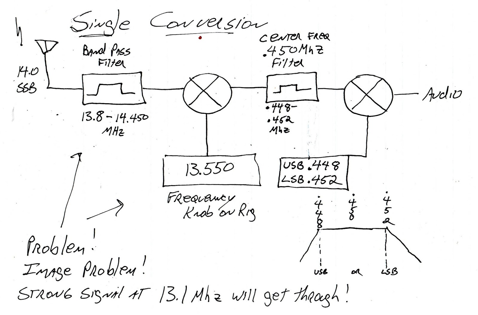
And here is a drawing that shows how a single conversion superhet with a fixed or switchable (usually crystal-controlled) BFO works:
Earlier this month I did a blog post on my repair of a broken DX-390:
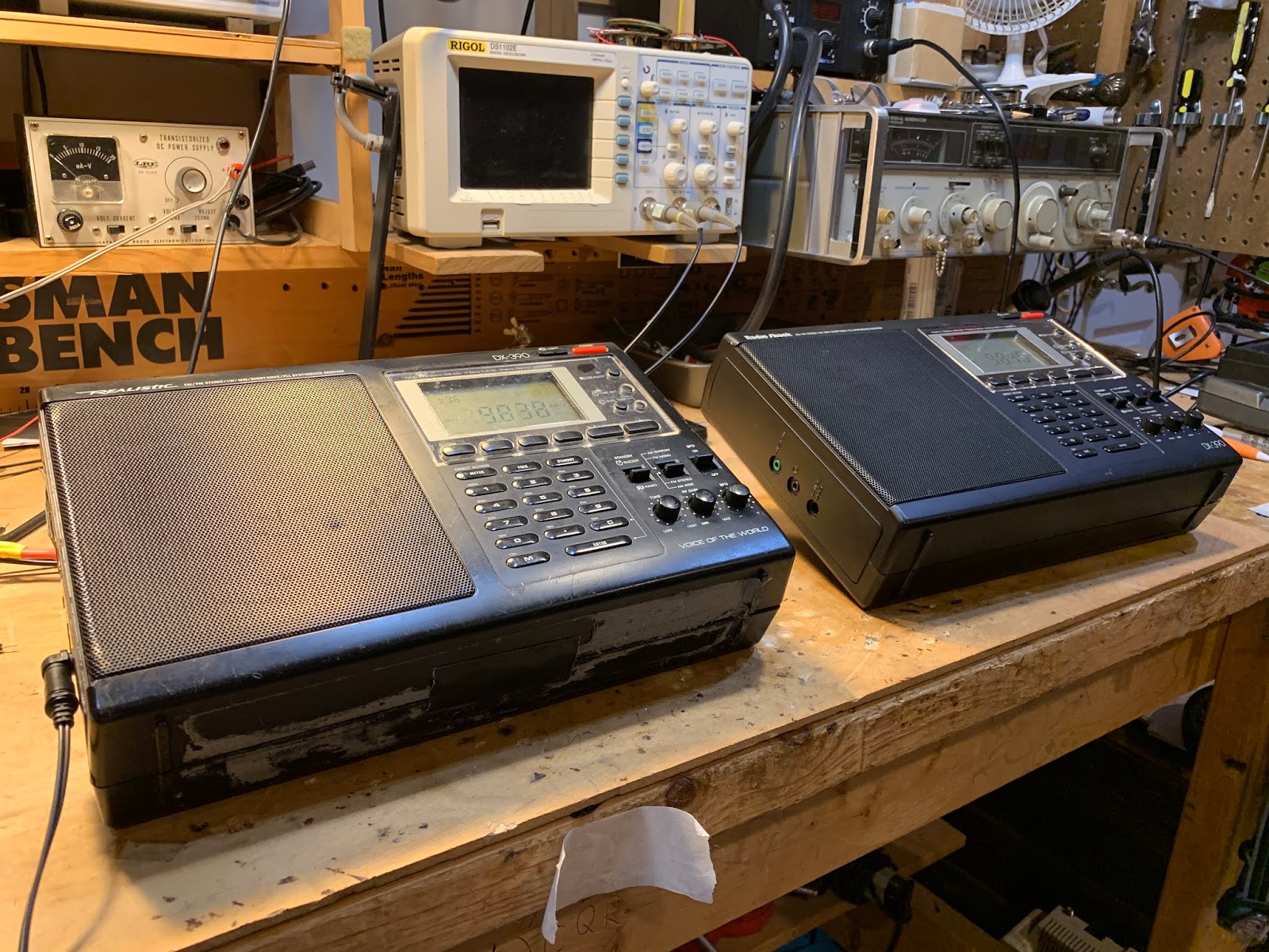
I’ve had this Radio Shack DX-390 portable receiver since the early 1990s. I bought it when I was in the Dominican Republic. It accompanied me on some interesting trips to the Haitian border, and on one very memorable 1994 trip to the Haitian capital. I have made some CW contacts with it serving at the inhaler.
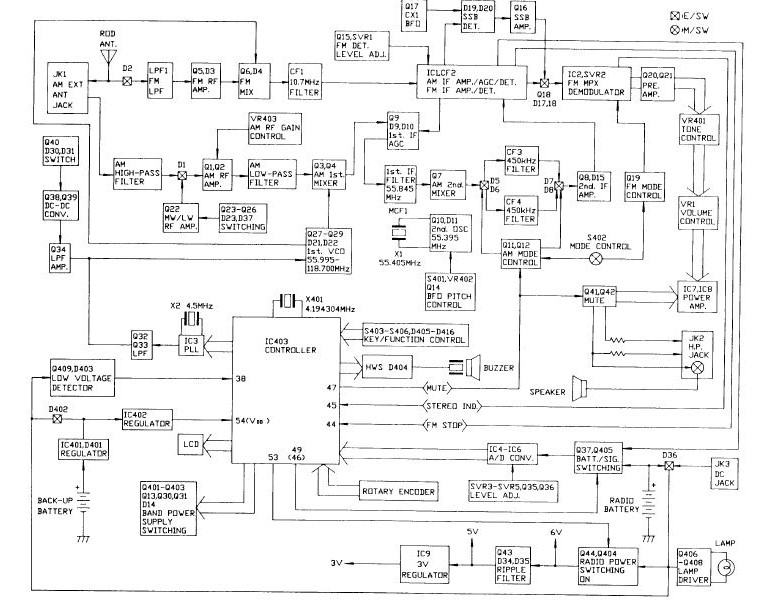
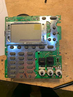
Click on the diagram for a better view. It is a dual conversion superhet. First IF is at 55.845 MHz. There is a big 90’s era IC-based PLL oscillator that runs from 55.995 to 118.7 MHz — The main tuning dial moves this oscillator. Second IF is at 450 kHz. There is an oscillator at 55.395 that takes the signal down to 450 kHz. Selectivity (not a lot) is provided by ceramic filters. Finally there is a product detector and a 450 kHz oscillator that produces the audio. While there are many mystery chips in this receiver, there is also a lot of discrete-component analog circuitry in there — it is kind of a pleasing mix.
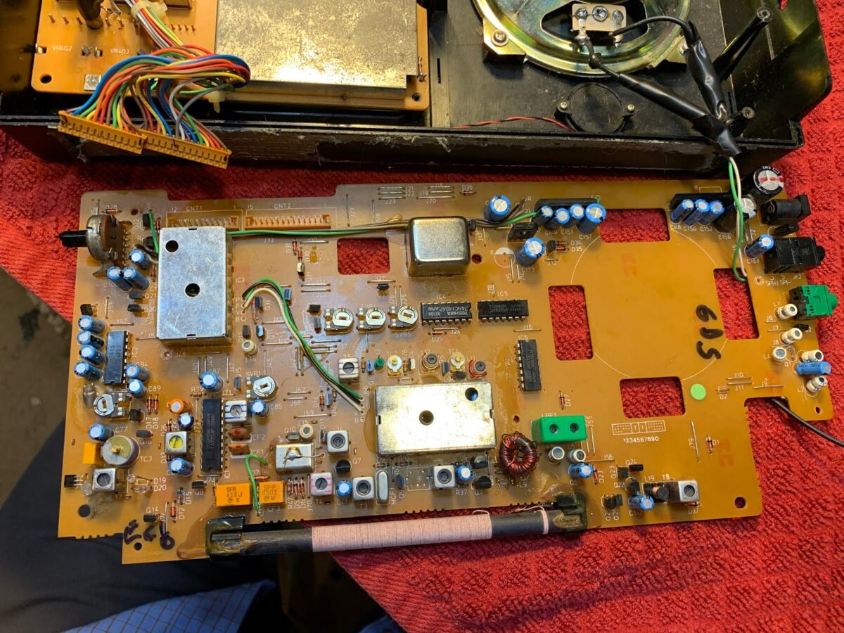
DX-390 Main Board. Note kludged toroidal replacment for L10 (just above ferrite antenna)
The old DX-390 suffered a lot of wear and tear. The case is very beat up. The most serious problem was that at some point, probably on a cold, dry, winter day in Virginia, static electricity took out the FET in the receiver’s front end. I made a half-hearted effort to fix it, but it never really worked properly. I occasionally found myself thinking of this receiver. I spotted one on e-bay not long ago, and bought it. This newer one was in very nice shape. But that old one was kind of staring at me from the corner of the shack. “C’mon radio man,” it seemed to say, “can’t you fix a shortwave receiver?” So this week I took up the challenge. First the FET. I had kludged an MPF102 in there, but that didn’t seem to work well. Internet fora seemed to think that a J310 would do better, so I installed one of them — it did seem to work better. (Note: Pete Juliano likes J310s — TRGHS.)
Kludged in J310. And two sets of back to back diodes
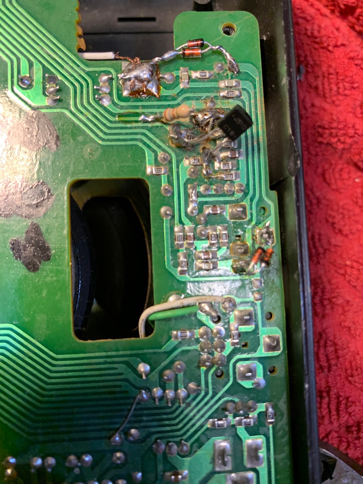
During my earlier repair effort I had apparently destroyed the front end output transformer (L10) but I discovered that I had replaced this with a toroidal transformer. It still worked, so I left well-enough alone. I was pleased that the old receiver was receiving OK, but there was a problem: The “BFO” control wasn’t working. The BFO would come on, but turning the BFO control did not vary its frequency. At this point I discovered that while there are many copies of the DX-390 service manual and schematic on the internet, all of them have seriously degraded copy quality right around the parts of the circuitry that I needed to study. Sometimes Murphy overpowers the Radio Gods. It took me a while to get a useful schematic of the BFO control mechanism. BFO is a bit of a misnomer here: the control actually shifts the frequency of the 55.395 MHz oscillator that drives the second mixer. See Block diagram above). There is a varactor diode in the base circuit of a BLT oscillator circuit. Turning the BFO control varies the voltage going to the varactor thus causing the oscillator frequency to slide up and down. But mine wasn’t moving. And that was a problem. So I dove right in, trying to figure out why it was oscillating, but not shifting in frequency. At this point I discovered that I too am afflicted with the disease that Pete Juliano suffers from: Fat Finger Syndrome. That BFO control circuit has a nice big 100k pot, but all the fixed resistors and caps were surface mount and SMALL. As I poked around trying to troubleshoot, I managed to make things worse. It turned out that the lead carrying 6 volts to the BFO control circuitry had broken. But before I discovered this, I managed to do all kinds of damage to the board. I lifted two PC board pads (I should have turned down the temperature on my soldering iron). Then, when I tried to fix this, I managed to put a solder bridge across two parts of the circuit that definitely should not have been connected. This resulted in a bizarre BFO situation. From the center position, turning the BFO to the left OR TO THE RIGHT would move the BFO in the same direction. So I could tune in an SSB station by turning to the right, or by turning to the left. That was just not right.
Lifted solder pads. And small wires that now bridge the gaps
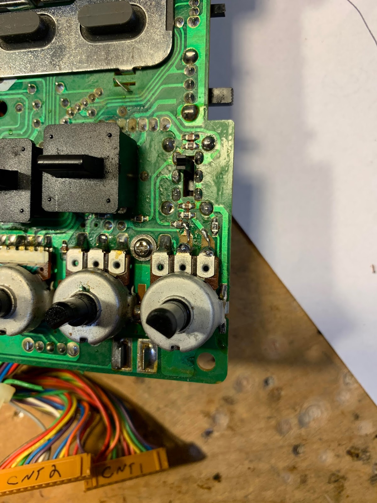
Uffff. It took me a while to find that fault. While trying to figure this out, I built the circuit in LTSpice just to see what it was SUPPOSED to be doing. This helped. Eventually, through careful inspection with magnifying goggles, I found a solder blob, and removed it. Now all was right with the universe. Even though I had caused most of the trouble, it was still quite satisfying to fix it. Some additional observations on the DX-390. — It really is a Sangean ATS-818 in disguise. Just look at the marking on the PLL board. If you can’t find a decent DX-390 schematic, just use an ATS-818 schematic.
ATS 818 marking along the bottom (green) part of the PLL board
— The service manuals on these receivers are quite good: the include bloc diagrams, detailed alignment instructions, and even voltage charts for all the chips and transistors. Impressive and useful. — The static discharge vulnerability is hard to understand. There is so much cool circuitry in these receivers, why not add four simple diodes? Not wanting to repeat this saga, I went in and put two sets of back-to-back small signal diodes in each receiver: one set on the telescoping antenna, and other at the input for the external antenna. Curiously, on the newer receiver, it looks like a previous owner had gone in and tried to address this vulnerability — but he did a very incomplete job. He just put ONE diode between the external antenna input and ground. I had always thought that two diodes back to back would give you good protection from static discharge. And I don’t think that single diode protects the front end in any way from discharge coming in from the telescoping antenna.
This was a good project. I got more familiar with general coverage dual-conversion receivers. And I got reacquainted with an old receiver that I liked a lot. Both receivers could probably use some alignment. I’ll take that up next.
A while back Fred KC5RT sent me a nice collection of parts, including some 6 MHz crystals. I had been thinking of making a converter to put ahead of my Q-31 receiver. When Fred’s 6 MHz rocks arrived, I knew that The Radio Gods Had Spoken (TRGHS). I found some NE602 chips in the junk box. I used an Altoid-sized box for the case. The toroids are from W8DIZ. I use trimmer caps from KC5RT to resonate the input and output circuits. Hooray! Now I can listen to 75 Meter AM on the Q-31. I may have to build a transmitter to go with this contraption. Thanks again Fred.
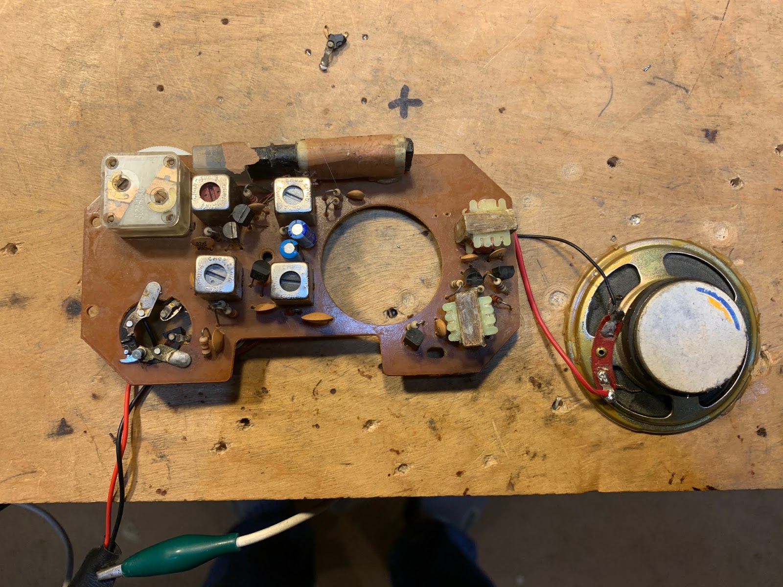
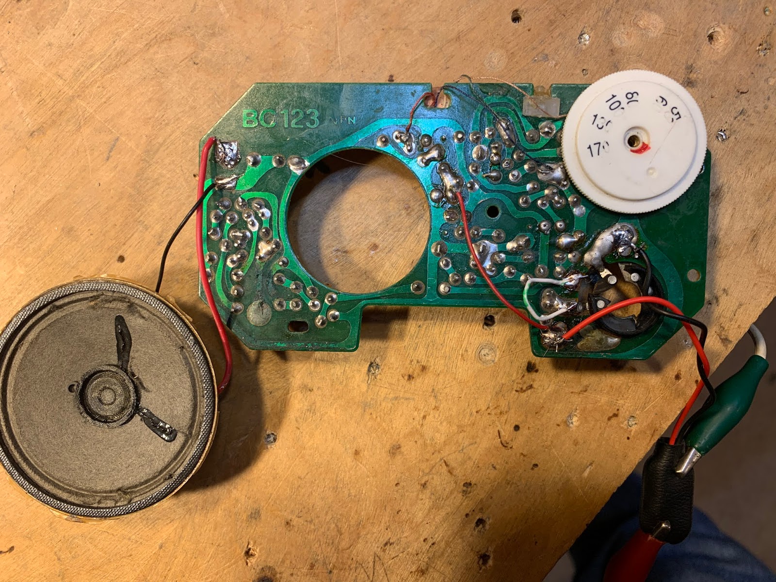
One of the great things about having a “miscellaneous” box in an otherwise well-ordered junk collection is that rummaging through that box will often send you off on fun and interesting radio adventures. I was rummaging yesterday and I came across the guts of the little AM radio that used to be mounted on my bicycle handle bars. I last mentioned this in 2011 :
I was just about to cannibalize this board. The IF transformers were almost certainly at 455 kc and I could use a few of those. But then I started thinking and Googling and trying to figure out the circuit. That all led me this the site that provided the diagram below:
Six transistors, four transformer cans, two audio transformers. Yea, that’s pretty close to what I was seeing on my board. So of course I had to see if I could get it going. I hooked up a 9V battery. I connected the pot wiper connection directly to the connection at the top of where the pot had been (it had disintegrated). It works! It is inhaling nearby WFAX, Falls Church, Virginia.
You will notice that the transistors in the circuit above are PNP. I had assumed negative ground and had hooked the battery up accordingly. No smoke was released and the thing worked, so I guessed that I had assumed NPN correctly. Sure enough, perhaps aware of the PNP ancestry, the manufacturer had marked my board “BC123 NPN”!
The author of the book I linked to above dubbed this circuit the “All Japanese 6” — an obvious allusion to the All American 5.
I see real potential in these AJ6s. A few mods to the front end and you could be shortwave listening, perhaps on 31 meters!
BTW: The space on my handlebars formerly occupied by that little AM radio is now taken up by a Bluetooth speaker that plays tunes streamed to my I-phone from Pandora as I make my way down the same old Washington and Old Dominion bike path. Progress.