Our friend Dave K8WPE has been listening to old podcasts. He recently came across those in which Pete and I were talking about phase noise. He asked for some resources on this topic. Here is what I sent him:
Receiver performance expert Robert Sherwood explains it this way:
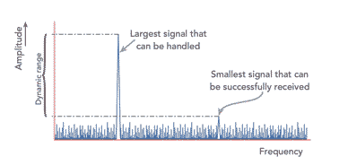
Old radios (Collins, Drake, Hammarlund, National) used a VFO or PTO and crystal oscillators to tune the bands. Any noise in the local oscillator (LO) chain was minimal. When synthesized radios came along in the 70s, the LO had noise on it. It is caused by phase jitter in the circuit, and puts significant noise sidebands on the LO. This can mix with a strong signal outside the passband of the radio and put noise on top of the weak signal you are trying to copy. This is a significant problem in some cases: You have a neighboring ham close by, during Field Day when there are multiple transmitters at the same site, and certainly in a multi-multi contest station. You would like the number to be better that 130 dBc / Hz at 10 kHz. A non-synthesized radio, such as a Drake or Collins, has so little local oscillator noise the measurements were made closer-in between 2 and 5 kHz.
I think a lot of the fretting about advanced receiver performance measurements are really kind of over-the-top, and mostly of interest to advanced builders who want the very best performance from their receivers. Most of the rest of us are happy if we can hear the band noise and separate the desired signals from the QRM. But I must admit that as time goes on, I find myself getting more and more finicky. I start to worry about gain distribution and dynamic range. But I don’t worry so much about phase noise because I am more of an LC oscillator guy and don’t make much use of the PLL devices (like the Si5351) that do produce more phase noise.
I’ve had many articles on the blog about about phase noise. Here they are:
I’ve been trying to get more rigorous in my evaluation of receiver performance. My HQ-100 is tuned to Radio Marti, and it sounds great. But how great is it really? And what about all the receivers and transceivers I have built? How good are they?
Our friend Dean KK4DAS is about to start the rehabilitation of his dad’s old HQ-170A. A search for that receiver led me to Jay Rusgrove’s very interesting measurement and analysis of old tube type radios. Jay’s results appear in the links below. More important is his very clear description of how the tests were done and what the results mean (link below). Also included is one link showing a discussion of Jay’s work.
Jay notes:
The decision of which boat anchor receiver(s) to own is seldom based on performance alone. A combination of favored manufacturer, period of manufacture, features, collectability or even just ‘looks’ often rank higher on the priority list than receiver performance. Even if one were interested in performance specs much of the available information is subjective as few receivers manufactured prior to the mid 70s have undergone standardized testing. Hard data on minimum discernable signal (MDS), blocking and two-tone IMD dynamic range is interesting to some operators and important in an historical context as it shows the progression of receiver development.
Jay designed the very first real transmitter that I homebrewed (The VXO 6 Watter from QRP Classics). Jay has been mentioned many times in the SolderSmoke podcast and blog:
Mr. Carlson (VE7ZWZ) is launching a series of videos on the restoration of some old boatanchor receivers. I have been working on an old HQ-100, so this all resonates well with me.
He asked for viewer input on which of these receivers he should work on first. I voted for the SP-600 because I wanted to see how difficult it really is to change out the infamous Black Beauty capacitors. My second choice was the R-390, but I warned Mr. Carlson that he might need a chassis crane for that one. No kidding. Really.
I look forward to watching the series. Thanks in advance Mr. Carlson.
Heck, he has an S-38E on the shelf above his bench. He is clearly one of us. What is his callsign?
This morning I watched the first and last of his 10 videos on his superhet receiver project. Very cool. Lots of good info in there. And there is something for everyone: Arduinos and Si5351s, along with a lot of standard analog circuitry. The first episode appears above.
The variable bandwidth filter looks very interesting. And there was a nice shout-out to Charlie Morris and one to Hans Summers.
I really like his effort in episode 10 to measure Minimum Discernible Signal using commonly available test gear. This helped me in my effort to get more rigorous and serious about receiver performance measurement.
Darren has many other excellent projects on his YouTube channel. My Hammarlund HQ-100 receiver started giving me trouble this week, and I was debating whether or not to fix the old thing. Darren’s channel provided the inspiration I needed. It will be fixed!
Please subscribe to Darren’s channel. And spread the word about his videos. We definitely want him to make a lot more.
PARTS CANDY out of Chicago produces quality test leads for your bench. The guy who runs the company is Carlos, and he is one of us. He is an electronic tinkerer. See the ad on the left hand column of the SolderSmoke blog. Just click on the picture of the test leads and you will be taken to Carlos’s ebay store. Go for it.
Mailbag
Walter KA4KXX in Orlando — Diodes in BITX Bilats — Why? Farhan says To prevent reverse junction of off transistor from conducting and clipping waveform.
Tony G4WIF — Audio test gear and G3ROO paraset
Todd K7TFC Pine boards, TIAs and 12 meters
Dean KK4DAS Ceramic Variable Oscillators on 40. Juliano Criteria?
Mike WU2D VFOs and Temp compensation. ARC-5s
Chris KD4PBJ A really nice parts care package — Thanks Chris!
Steve M0ECS. Inspired by SS, moved something off the Shelf or Box of Shame.
Jason KD2RKN Building a DC receiver. It is all our fault.
Chris Mannon in Indiana joining the CBLA
KC4GMH is listening!
Ed N2XDD has been armed with a 3.579 MHz crystal.
Harvey Wa3EIB working on his museum
Tim AG4RZ is BACK IN THE SOLDERSMOKE!
Fred KC5RT — an old friend — recommends Bangood RF sig gen for 88 bucks.
Shlomo 4X4LF listening and homebrewing from a Kibbutz in Israel.
Chuck KF8TI was a Peace Corps Volunteer in the Philippines.
As I finished up the receiver on my 17-12 SSB transceiver, I started to wonder — how good is it?
Sure, I could hear stations on both bands, and when I got started as a homebrewer that was enough for me. But now, I find myself wondering about receiver performance. Did I get the gain distribution right? Do I have too much gain ahead of the mixer? Ahead of the crystal filter? Is the receiver generating too much noise? Can I hear the band noise? If not, why not? Do my circuits lose linearity in the presence of strong signals? What is my dynamic range?
This is a big complicated subject that takes time to master.
I am just beginning. I found the video above to be very helpful.
I was jealous of this fellow’s audio spectrum analyzer, but then Tony G4WIF told me that the the analyzer that this fellow was using was really just a sound card and some software. I quickly found a similar piece of free software that lets me do the same thing he did: Look at the audio output of my receiver and watch what happens as I put an RF signal of varying levels into the antenna port.
I am using Visual Analyzer, a free program out of Italy:
My name is Alfredo Accattatis; I love electronics and software, and I have been working for years in commercial companies as software/firmware engineer and software designer. I’ve been writing programs for embedded systems (with DSP and MICROCONTROLLERS), for PC, for Avionic Computers and even for Mainframes, using C, C++, Pascal, Ada, REXX and assembly. I starting write VA during my free time just for fun and using (also) my DSP experience. The program was and is completely FREE.
OK , so I’ve finished building my new 17-12 Dual Band SSB Transceiver. I am now testing it out on both bands. A big question I have is this: how good is my receiver? Did I get the gain distribution right? Is it generating too much noise? Are any of the stages too vulnerable to distortion in the presence of large signals?
These kinds of questions are at the heart of receiver design. Many of us have for years just thrown together amplifiers oscillators and mixers, and have been pleased if we could copy signals on the ham bands. But could we have been doing it better?
This is a very complicated issue, and unfortunately much of the literature is plagued by jargon and unnecessary complexity. Rarely do we find something that goes from the general to the specific and explains what it is we are trying to achieve: We want the receiver to be sensitive, but we don’t want it to be so sensitive that it distorts with strong signals. It will make some noise, but we don’t want the receiver’s internal noise to be stronger than the noise coming in from the antenna. The “front end” stages are very important because any flaws there will be amplified by the follow-on stages and will “cascade” down through the receiver. Bandwidth is very important.
This morning I found (again!) a document that defines terms in a very clear way. Be sure to check out the footnotes mentioning Dave Newkirk and Wes Hayward! FB! Here it is:
Here is an update on the 1712 transceiver project. The receiver circuitry is done and I can listen on 17 and 12 meters. In this video I was using my 75 meter doublet tuned to 17 meters (reception on 12 was pretty good using this antenna). As you can see, I found a temporary solution to the VFO dial problem — I am using the cardboard tube from a coat hanger super glued to a knob. The tube fits snuggly over the shaft from the VFO assembly.
With just two TIA amps (one on either side of the 10 pole filter) and the AF amplifiers, I now have it inhaling on 17 meters. But nothing heard so-far on 12. On both bands I can hear the band noise, but just barely. So I may try some RF amplification ahead of the mixer. What do you guys think about this? I think the two TIAs and the crystal filter are providing 30 db of gain.
I want to get the receiver circuitry working well on both bands before I build the T/R and transmit amplifier circuitry.
It is nice to have a project on the bench!
I am trying to find a shaft extender or adapter for that big beautiful HT-37 main tuning cap. The shaft on the capacitor has a width of 1 cm or 0.393701 inches. I need something that will grab onto that and allow for the connection of a tuning knob. Please search your junk boxes!
Dennis WC8C is the event coordinator for the radio club in Michigan that I recently spoke with. He mentioned to me that he was working on a homebrew 6 meter rig. FB Dennis. I see lots of tribal wisdom in your approach, especially in your decision to do this in a stage-by-stage modular form.
Dennis’s rig is obviously a work in progress, so if anyone out there has any helpful hints (especially on the carrier suppression and on the testing for spurs and splatter) please share them with him via e-mail or blog post.
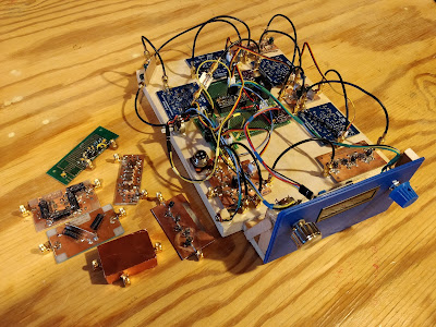
This is my 6 Meter homebrew transceiver, currently work in progress.It is a single conversion super –heterodyne design.I constructed each stage independently with SMA connectors.This is so I can re-make sections as needed, and will allow me in the future to swap sections to experiment with alternate designs.The VFO and BFO are controlled using a SI5351 with an Arduino micro controller.I currently have separate SI5351 modules for VFO and BFO because I suspected issues with cross-talk.These issues may not actually be real, so once I am happy with the performance, I will test again with just one module to see if it is OK.The Power Amp is still on the to-do list, so output is well under 0 DBm
The Blue boards were designed by me and ordered on-line.The other boards I etched myself.Construction is mostly surface mount because I find it easier than drilling all the holes.SMD components are mostly 805 and 1206 size. Transistors are SOT23.
The Band Pass filter is a 5 coil design made with air-core inductors.
3 bi-directional termination insensitive (TIA) amps are used (blue boards).Total RX gain is about 44db.Total TX gain is about 16db.Each board has its own independent RX/TX switching circuitry (mosfet based) and is fed with +12.5, GND, and RX/TX logic signal from the Arduino (3V logic and up will work)
The Mixer and modulator are both Diode Ring mixers.
The 12 MHz SSB filter is a crystal ladder filter similar to the one used in the uBitx.
The Mic and audio pre-amp (also a blue board) is made on a modified TIA amp board.I had 10 of these boards made, and the needed circuitry was largely the same, so I modified the board with a rotary tool and jumpers.
The Audio amp is a PAM8403 module and drives a headset.I did make some modifications to the module so it runs in-spec and to eliminate the power on audio pop.
The challenges I have been having are mostly related to spurs, splatter, carrier suppression and TX audio quality.I have been gradually tweaking these things to improve operation before I start on a power amp.My IF is 12 MHZ, and I was using the LSB side of the crystal filter because it is sharper (VFO 62 – 66 MHz) but have recently changed over to the USB side of the filter (VFO 38 – 42 MHz).This eliminated the spurs I was seeing near the pass band.I still need to make some adjustments to the crystal filter as it is too broad.
I still have some splatter and audio quality seems low, but I am starting to doubt my test setup.I see the splatter on the RTL SDR, but I don’t see it on the Tiny SA.The spatter happens at ~160 KHz intervals.I am hoping to find someone local with a better spectrum analyzer to help me verify if it is the rig or my SDR dongle/test setup.
The modules to the side of the picture are my rejects/experiments.The one covered in copper shows how I eventually will shield all the modules.I 3D printed a cover for the board, when wrapped it with copper tape, soldered to the bottom ground plane.The one shown is a diode ring modulator.For some unknown reason the carrier suppression is rather poor.I had previously made a junk-box modulator that had much better carrier suppression.I don’t know why it is better than the one I more carefully made for the radio, but until I figure it out, I am using the junk box version.The junk box modulator uses unmatched schottkey diodes, whereas the “final” one uses a 4 diode SMD package because I wanted them matched – I thought this would be better, but maybe not.
6 weeks in the DR for Bill One contact on uBITX. More SW listening. Repaired my Chrome Book in Santo Domingo! Christmas Present for All: James Web Space Telescope launch
First, thanks to all who sent in suggestions. They came in literally from around the world, and this is a demonstration of the IBEW in action. I used or at least tried all of them. They were all good ideas.
Following Vasily Ivananeko’s pseudonymous suggestion I rebuilt the carrier oscillator (apologies to G3YCC). I used the carrier oscillator/buffer circuit from Farhan’s BITX20.
Henk PA0EME said I should look at the signal level at the input ports of the NE602 mixer. Henk was right — the VXO input was far too high. I lowered it, but the problem persisted.
At first, I thought that the spur in question was so small that it would not show up on the air. I could not see it in the TX output using my TinySA spectrum analyzer. That was good news and bad news: Good that it was not showing up on the air, bad that I could not see it in the TinySA and use that image in the exorcism.
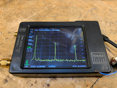
At first I thought that the spur was being caused by the 10th harmonic of the carrier oscillator and the third harmonic of the VXO. This seemed to fit. So, following VK3YE’s sage advice, I built a little 69 MHz series LC trap (using a coil sent by AA1TJ, on a board CNC’d by Pete N6QW). That trap succeeded spectacularly in crushing the 10 harmonic. Look at these before and after shots on the TinySA:
Before Trap
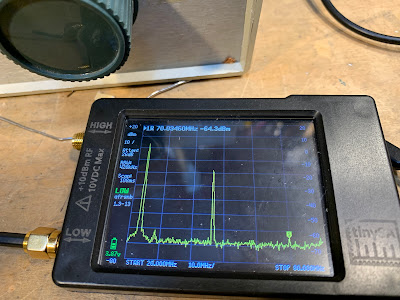
After Trap
Spectacular right? But guess what? The problem was still there.
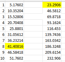
I scrutinized the situation once more. I realized that the spur would be more visible if I put the TinySA on the input of the transmitter’s PA (a JBOT amp designed by Farhan) as opposed to putting it on the output. Watching the spur and the needed signal move in the TinySA as I tuned the VXO, I realized that they were moving in opposite directions. This indicated that the spur was the result of a carrier oscillator harmonic MINUS a VXO-generated frequency (as the VXO frequency increased, the spur frequency decreased). Looking at my EXCEL spread sheet, I could see it: 8th harmonic of the carrier oscillator MINUS the main output of the VXO.
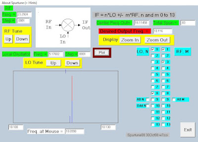
To confirm this, I plugged the values into W7ZOI’s Spurtune program. Yes, the spur popped up and moved as predicted.
For further confirmation I shut down the carrier oscillator by pulling the crystal from the socket, and then just clipped in a 5.176 MHz signal from my HP-8640B signal generator (thanks KB3SII and W2DAB). Boom! On the TinySA, the spur disappeared. Now I at least knew what the problem was: a harmonic from the carrier oscillator.
Following good troubleshooting practice, I turned off the gear and went to bed. When I woke up, an idea came to me: Before launching into a lot of filtering and shielding, just try running the carrier oscillator at a lower voltage, seeing if doing so might reduce the harmonic output. I disconnected the carrier oscillator board from the main supply and clipped in a variable voltage bench supply. Watching the signal on my TinySA, I watched as the spur completely disappeared as I reduced the voltage from around 13V to 10V (see video above). The main signal frequency level did not change much. I tested this by listening for the hated extra tones. They were gone. Exorcised.
Key lessons:
— Spur problems are difficult to troubleshoot. Armstrong’s superhet architecture is, of course, great, but this is definitely one of the pitfalls. Single conversion makes life easier. IF selection is very important. Choose wisely!
— When looking at the TinySA as you tune the rig, pay attention to which way the spur is moving. This provides an important clue regarding the combination of harmonic you are dealing with.
— The TinySA is a very useful tool. It seems like it is easier to use than the NanoVNA (which is also a fantastic tool).
— It can be fun and rewarding to re-visit old projects. In the years between original construction and the re-look, new test gear has become available, and the skill and experience of the builder has improved. So problems that once seemed insurmountable become fix-able.
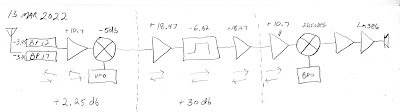
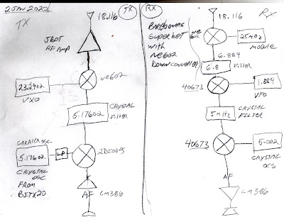
— Thinking through a problem and thinking about possible solutions is very important. It pays to step away from the bench to think and rest. Rome wasn’t built in a day. Here’s a rough block diagram that I drew up (noodled!) while trying to figure out this problem:
Here we see them struggling to find the proper frequency for one of the oscillators in a dual conversion UHF receiver from the Apollo program. For the VCO, they needed a crystal in the 23 MHz range. They faced the same questions we face: Series or parallel? Load capacitance? Fundamental or overtone?
It just so happens that at this moment I have on my bench the 17 meter SSB transmitter that I built some 20 years ago. And the VXO in it uses crystals in the 23 MHz range. TRGHS. (More on the spur problem with this rig soon. The solution does involve the 23 MHz VXO.)
Very cool that CuriousMarc found a manufacturer still willing to produce custom-made crystals. JAN flashbacks! LapTech Precision in Canada: https://www.laptech.com/index.php
The video above is Episode 8 in the Apollo Comms series. If you go back one episode, you can watch Marc and his assistant troubleshoot the NASA Apollo UHF receiver. They use very familiar troubleshooting techniques. This reminded me a lot of what we do with older, potentially modified gear. They were able to figure out what was wrong and how a mod had changed things. This set the stage for the crystal replacement selection we see in Episode 8. Here is Episode 7: https://www.youtube.com/watch?v=87qA41A_Ies
Note: The frequencies in this Apollo receiver were listed in Megacycles, not Mega Hertz.
Thanks to Bob Scott KD4EBM for alerting us to this.
Is it really homebrew if you buy a bunch of already-stuffed PC boards and connect them together?
Is it really a homebrew receiver if 90% of the components are inside one chip?
Is it really homebrew if most of the signal processing is done in your computer (that you definitely did not build)?
The comments below the article are interesting. There we see some of the same arguments used by ham radio operators who are more inclined toward click-and-buy. They argue that since none of us are making our own resistors and transistors, we are ALL therefore click-and-buy people, so we should just get over it and pull out the credit cards. Some commenters carry this to extremes and ask if the real homebrewers are out there mining the copper for their wires.
The debate seems to spill over into the software area: One person asks if it is really DIY if you are using software libraries that contain code written by someone else. Or to be truly DIY should you write all of your own code in assembly language?
There is one very insightful comment about hams who are inclined to disparage the homebrewing that they did in their youth. We often hear this: “Oh, I used to build my own gear, but now-a-days I just buy commercial transceivers — they are so much better.” As if homebrewing was a folly of youth, something that they grew out of (and up from) as they became able to afford the latest ham radio appliances. As if homebreweing were a regrettable thing that was done only out of necessity. This is, I think, sad.
I think I’m a lot closer to the traditional concept of DIY than I am to click-and-buy. I still prefer LC oscillators to Si5351/Arduino combos. I prefer traditional filter rigs to SDR rigs. And I prefer to make my own crystal filters. I don’t like to use ICs unless I really understand what is going on inside them (so I can be comfortable with an NE602 or an LM386, but I’m not comfortable with a CPU chip that may have millions of transistors in it). But I am not homebrewing my own transistors nor am I mining copper.
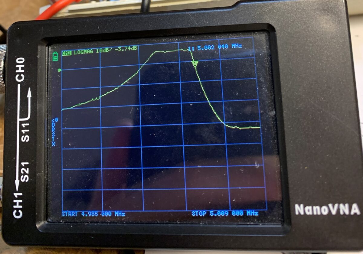
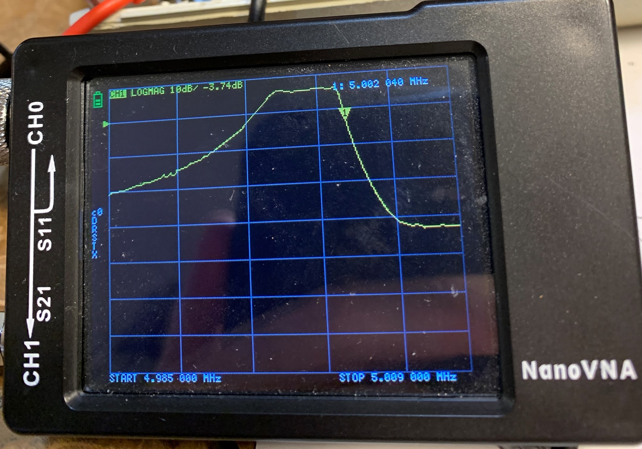
Armed now with a NanoVNA, I took a look at the passband of the 5 MHz filter in my Barebones Superhet (BBRX) W4OP built it on a Circuit Board Specialist Board. He put a 5 MHz CW filter in there; I broadened the passband for phone by changing the values of the capacitors. Here is what the passband now looks like in the NanoVNA:
This is what DeMaw would call an “LSB filter.” You would get much better opposite sideband rejection by using it with an LSB signal, placing the BFO/Carrier Oscillator slightly above the passband, in this case near 5.002 MHz.
When I first built the down converter to get the 18.150 MHz signal down to the 7 MHz range (where I had the receiver running) I used an 11 MHz crystal for the NE602’s local oscillator. But this created a big problem: 18.150 – 11 = 7.150 MHz. That is in the 40 meter band, but note: NO SIDEBAND INVERSION. Then in the BBRX 7.150 MHz – 2.150 MHz = 5 MHz (the filter frequency) but again: NO SIDEBAND INVERSION. The signal started as a USB signal and remained a USB signal.
I briefly tried shifting the BFO frequency to the other side of the filter passband. If I could get it to around 4.985 MHz, it might work, but because the filter passband was so large, and because the crystal frequency was so low, I was unable to shift the crystal frequency that far. In any case the results would have been less than ideal because of the “LSB” shape of the filter. Back to the drawing board.
I decided to cause one sideband inversion.
At first I put a 25.175 MHz crystal module in my down converter. This shifted the 17 meter phone band down to the 40 meter CW band. It worked, but I cold hear strong 40 meter CW signals being picked up by the wiring of the receiver (the box is plastic!). I went back to the module jar in search of frequency that would move 17 meter phone to the 40 meter area (so I would not have to re-build the BBRX front end) but outside the actual 40 meter band.
I ended up using a 25 MHz crystal in the down converter. 25 MHz – 18.150 MHz = 6.85 MHz WITH SIDEBAND INVERSION. After checking on the NA5B Web SDR to see that there are no strong signals in the 6.835 to 6.89 MHz range, I retuned the output circuit on the converter and tweaked the input capacitor on the Barebones. I shifted the VFO frequency down to 1.835 to 1.89 MHz and put the BFO at 5.002 MHz. The receiver was inhaling on 17 meter SSB.
One more change to the BBRX: in his June 1982 QST article, DeMaw warned that trying to get speaker level audio out of the 741 op amp that he used would result in audio distortion. And it did. So I put one of those little LM386 boards I have been using into the BBRX box. I just ran audio in from the wiper of the AF gain pot. It sounds good.
In effect this is my first double-conversion receiver. I usually prefer single conversion, but this project has highlighted for me one of the advantages of double conversion for someone like me who eschews digital VFOs: Starting with a crystal filter at 5 MHz, with double conversion I could keep the frequency of the LC VFO low enough to ensure frequency stability. That would have been impossible with a 5 MHz IF in a single conversion 17 meter rig. But if I were starting from scratch for a 17 meter rig, I could stick with single conversion by building the filter at 20 MHz, keeping the VFO in the manageable 2 MHz range.
Now, on to the SSB transmitter. The Swan 240 dual crystal lattice filter from the early 1960s needs some impedance matching.
(Why the T/R diodes in the BITX 20 amplifiers?) National Receiver.
Bill’s Bench Farhan’s Talk to RSGB got me thinking of VHF 2 meter AM. 2 meter Benton Harbor lunchbox madness. SuperRegens Super Strange. I broke my Maplin AF Sig Gen in the process. Fixed it. Playing with MMMRX again. Put in 6 kHz ceramic filter. Sounds great SSB and AM. Swept IF with noise, TinySA, and NanoVNA. Need better noise gen. Mod to listen with TinySA (on blog). Thinking of 17 meter /12 meter Dual-Bander IF around 21.4, VFO around 3.41 Mhz. Thoughts? Sweeping double half lattice filter from Swan 240. UGLY.
MAILBAG: — ROOTS OF MAILBAG: Radio Moscow, Havana Cuba, HCJB, others. — Thomas K4SWL of the SWL Post: Could have been worse! Stairbag?
— MY NOVICE LOG — Heard back from ex-WN2RTH ex-WN2FLK ex-WB2RKK. — Drew N7DA worked Wes W7ZOI in Sweepstakes. FB. — Peter VK2EMU The movie Frequency and the Magic of Heathkits. Good, but not that good! — Thomas KK6AHT! Our old friend. Minima! Now has a young son! FB — Chuck WA7ZZE Saw QST profile. Sympathizes with Two-er trouble. — Tim M0CZP. Spell corrector. Vatican Diodes. Infallible! — Ramakrishnan VU3RDD Working on a NORCAL and a noise cancellation arrangement. — Skip NC9O said I was 40 Hz off on 17. But he had a reason to KNOW! — Steve K9NVD Glad he’s a listener. — Bob KY3R Novice Nostalgia. Should he use 75 watt bulb for dummy load? Yes! — Todd K7TFC Video about why solder smoke goes into the face. — Anthony VU3JVX Homebrew Antuino. I ask for help in moving freq to 450 kHz. — Jack NG2E Building Pete’s DC RX. — Scott WA9WFA HBR-13 and MMMRX. — Stephen 2E0FXZ also got a FT-101 VFO. — Bob K7ZB on the air with 56 mW and a big antenna. — Dean AC9JQ Retired. — Allan WA9IRS Right to Repair update. — Farhan Invited us to Lamakaan ARC, Dec 11 or 12. Will be on QO100 Satellite Live!
— Many suggestions about my Apollo 11 Time Capsule. Still looking for ideas.
Happy Thanksgiving to all who celebrate this holiday!
This is Scott WA9WFA’s first homebrew construction project. He did an amazing job on a very complex project: a 13 tube superhet receiver. It features plug-in coils for multi-band coverage, dual conversion with IFs at 1600 kHz and 100 kHz, and several regenerative stages. Scott’s construction is top notch. He tells us that he had been working on this receiver for several years, so long in fact that some of his friends began to wonder if it really existed. Well wonder no more. Retirement has provided Scott with the time to finish this project.
I like the way Scott talks about the project in these videos. He puts it in the context of his long-standing goal of building his own high quality ham station. With the HBR-13 done, he is more than halfway there. We all know that the receiver is the hard part.
I agree with those who say that Scott should keep the plexiglass front panel. I think it looks very cool.
In the third video, Scott takes us on a cruise through the 40 meter band. The receiver sounds great. Lou EA3JE’s booming voice came through quite nicely from far-off Barcelona.
Congratulations Scott on building a truly outstanding receiver. And on making some great videos.
There is some additional background info on the HBR-13 in this blog post from back in September:
I really liked Nick M0NTV’s approach to making a crystal filter (see video above). He really simplifies a process that desperately needs simplification. I remember when I was building my first superhet receiver, I came across Doug DeMaw’s schematic for a crystal tester that would allow me to properly build the filter. But the piece of test gear was far more complicated than the receiver I was building. I never built Doug’s device.
Nick’s technique is simpler even than the G3UUR method that many of us have been using for years. Nick dispenses — wisely I think — with the need to calculate motional parameters, Q, and equivalent series resistance. This also eliminates the need to fidget around with the design software such as Dishal or AADE.
Nick uses the Cohn topology (good choice) and uses kind of an “informed cut-and-try” technique to come up with the capacitor values.
Filter impedance is determined with series trimmer resistors and the NanoVNA to watch the resulting passband. Nick says this is a Charlie Morris ZL2CTM suggestion. It obviously works very well — the ripple that would result from impedance mismatch is eliminated.
Nick’s determination of the best turns ratio for the impedance matching transformers is brilliant.
Nick apologizes for what he says is a long video. But it is only 30 minutes or so long, and if you are going to build your own superhet or SSB filter rig, it is well worth watching.
Three cheers for Nick and for Charlie! Thanks guys!
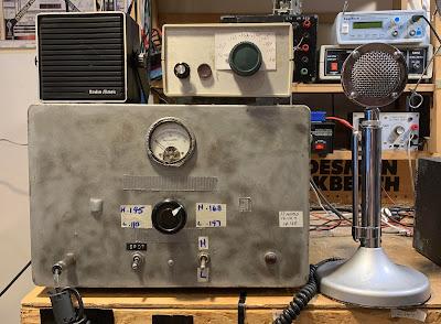
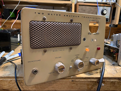
Farhan VU2ESE is largely responsible for this. He has recently been talking about VHF. (More about this in due course.). This started me thinking about my failed effort in London to get on 2 meter AM. My plan was to use the transmit portion of this HW-30 (above) with a 2-to-10 downconverter and my trusty Drake 2-B for receive.
Tony G4WIF also bears some responsibility: When I expressed interest in Farhan’s VHF work, Tony sent me two articles from SPRAT. Both of them were about super-regenerative receivers.
Farhan’s comments caused me to pull the HW-30 out of storage. I started poking around the transmitter. But then I noticed something: On receive, the AF amplifier was obviously working. Then, when I tuned through the 2 meter band, the rest of the receiver seemed to be working too. I fired up the HP-8640B sig gen on 2 meters and turned on the AM modulation. Indeed, the old receiver was inhaling!
This launched me into an effort to understand how super-regenerative receivers work. There are a lot of really weak explanations out there. You get the distinct impression that the person explaining the circuit does not understand it himself. This makes explaining it very difficult. I am not the only one to notice this phenomenon: Mike WU2D commented on this in one of his excellent super-regen videos. This one:
Mike very kindly said the operation of this circuit seems like “magic.” I was thinking more in terms of Voodoo.
Howard Armstrong discovered super-regeneration years after he invented plain old regeneration. The new discovery came around 1921.
It looks like VHF guru Frank Jones had very early misgivings about super-regeneration. In his 1934 classic 5 Meter Radio Telephony, Jones seems unenthusiastic about the circuit and about our ability to understand it: “To explain, simply, exactly how this form of detection takes place is not a simple matter, but some of its characteristics are easy to visualize.” In this book, Jones goes on to predict that super-regens will be superseded (!) by superhets. Indeed, in his 1961 book VHF for the Radio Amateur there are no super-regen circuits; all the receive systems are down-converters to HF receivers.
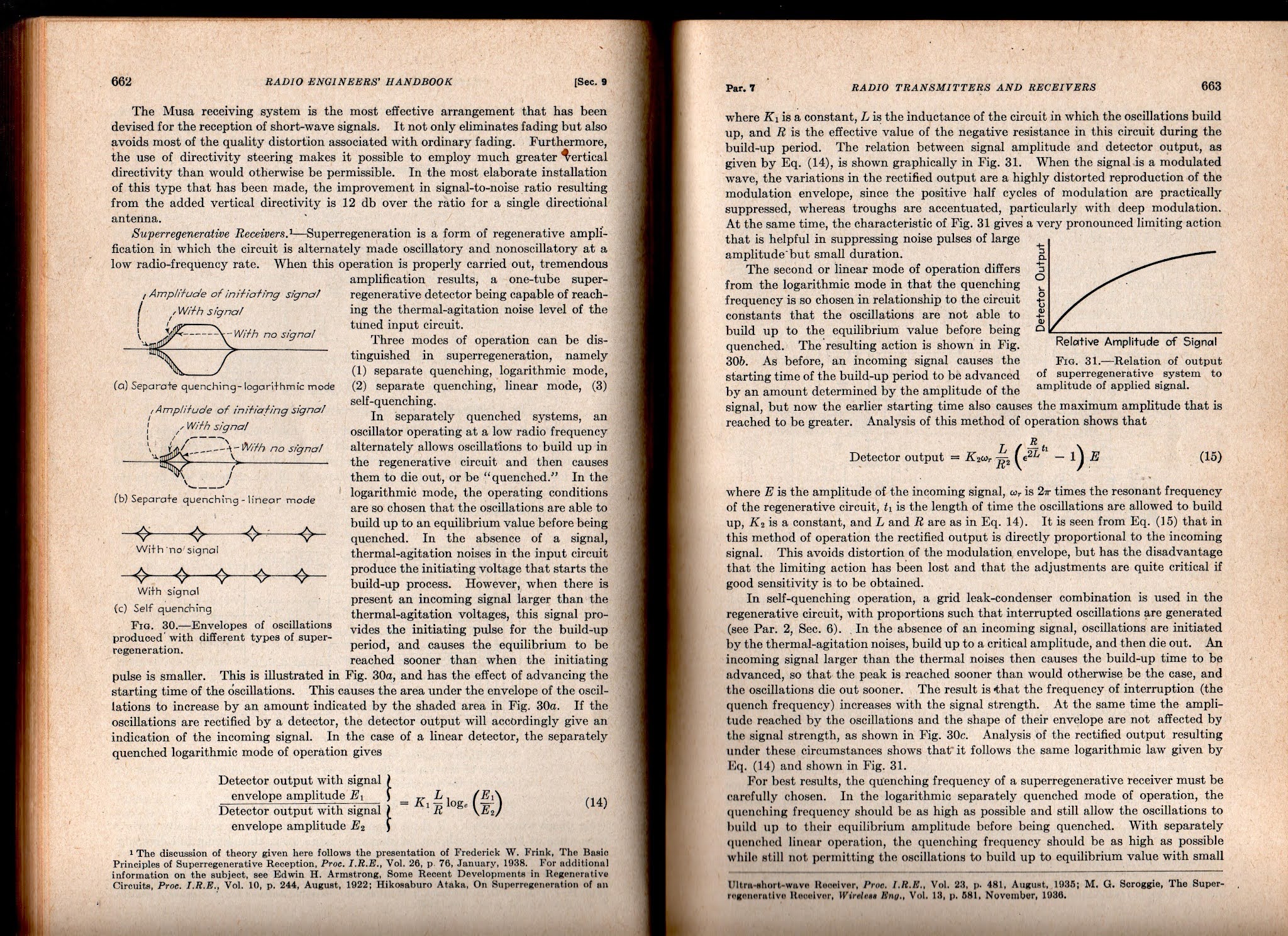
Still, with that HW-30 hissing away right next to me, I feel I need to understand how the super-regen works. I’m not there yet, but I’m trying. Here are some good resources:
But the best so far (for me) is from Frederick Terman (one of the founders of Silicon Valley) in his 1943 classic Radio Engineer’s Handbook. Click on the images for a clearer view.
I will definitely try to get the HW-30’s 5 watt AM transmitter going. I am not so sure I’ll do anything with the receiver. I think this is a matter of picking your battles and “finding joy.” I didn’t find joy in FT-8, so I stopped working with it. Same with my HA-600A, DX-40 Novice rig. Same with CW in general. And the same with SDR. I suspect that super-regen receivers may also fall into this category. I mean, let’s face it, if you are not fond of ordinary regens, is there any real chance that you will like SUPER-regens? Even Frank Jones seems to have disliked them. And there is a reason Howard Armstrong moved on to superhets — they are better! But still, that receiver is hissing away at me… Stay tuned.
Wow, Scott got his Mate for the Mighty Midget receiver to work and he is obviously overjoyed with the result. All of us who have struggled with a homebrew project know just what this feels like. And it is very cool that Scott got some useful guidance from Charlie Morris in far-off New Zealand. Congratulations Scott. I’m really glad you stuck with it.
Scott’s success comes at a good time: Pete N6QW is building W4IMP’s three tube “IMP” SSB transmitter (also from the 1960s). I accept responsibility for naming Pete’s project: It will be known as “Pete’s IMP” or, memorably, “The PIMP.” For a look at Pete’s rig go here:
Scott had problems getting Lew McCoy’s 455 kc crystal filter to work. So did I. It turns out that this is a very old problem, going back to World War II. In Don Stoner’s 1959 “New Sideband Handbook” on page 54 he writes of homebrew filters in the 400 to 500 kc range:
“Inexpensive crystal filters constructed from war surplus FT-241 type low frequency crystals are very popular with the ‘do it yourself’ hams. These CT cut crystals have been plentiful and relatively cheap for a number of years and are in the hands of many Amateurs. The general run of war surplus crystals may or may not be good. Experience has shown that one out of four of these crystals are usually defective in one way or another.”
Stoner was writing just 14 years after the war. Add another six decades to the age of these crystals — often decades spent in musty basements — and you can imagine the percentage of bad 455 kc FT-241 crystals increasing. So I think Scott is wise to seek an alternative to McCoy’s crystal filter.
Scott’s original build of the MMMRX receiver is just so nice. In the video he says he plans to go back to it after he gets the expanded version fully functional. He should definitely do that — his original version looks so good. I think it is probably very close to working properly.