Hans: Live and let live OM! Some people like their diodes up and red, others down and blue!
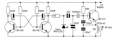
Any little diode would, of course, work as a switch, regardless of its possible varactor properties. When the diode is not conducting, that 5 pf cap in your SPRAT 134 circuit has one end floating. When the +2 volts comes in from the multivibrator, that little cap is fully across your 22 pf trimmer, and the frequency shifts.
I did some additional Googling this morning and found that Alan, VK2ZAY used this diode as a switch scheme in his early QRSS design. See:
http://www.vk2zay.net/article/180 Alan wrote “A small trimmer in the oscillator circuit is diode switched by the beacon controller to pull the oscillator an adjustable amount.” (He later went RED on us with upward pointing varactors!)
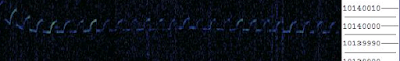
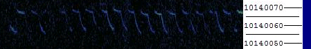
I did the test you asked for (shorting out the diode). Before I shorted it out, my freq counter shows the transmitter shifting from 10140020 to around 10140030. Shorting out the diode with a bit of wire puts the freq at 10140010, and it stays there.
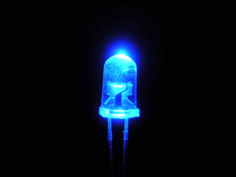
The switching scheme has a side benefit: You get a cool-looking LED that turns on and off with your keying.
73 Bill
— On Mon, 4/26/10, Hans Summers wrote:
From: Hans Summers
Subject: Re: [Knightsqrss] FSK LEDs: Red or Blue, Switches or Varicaps?
To: “Bill Meara”
Cc: knightsqrss@cnts.be, “g3zjo”
Date: Monday, April 26, 2010, 1:18 PM
Hi Bill
Currently it’s still offending my sense of correctness, having that
diode upside-down!
And also I’m still not convinced it’s behaving as a switch.
Even when reversed (i.e. Forward biased), the diode can still show a
variable capacitance effect, seemingly.
Please can you try shorting the LED and tell me what FSK
that produced? 73 Hans
On 4/26/10, Bill Meara
wrote:
I’m thinking that both configurations might work:
Perhaps with Red LED working in reverse bias mode, the diode serves as a
varicap, with the voltage from the multivibrator varying the capacity
and causing the FSK. I guess we’d call this the “diode as varicap” mode.
In the configuration that I am using, (which I guess we could call the
“diode as a switch” mode) the diode is FORWARD biased
by the voltage from the multivibrator. Then that output terminal goes
positive (mine goes up to about 2.35 Volts), the diode conducts, and the 5 pf
cap is effectively added to the circuitry between the crystal and ground. And
the LED glows (even with current severely constrained by the 1 Meg
resistor between the multivibrator and the diode. When the voltage from
the multivibrator goes below around .6 volts, the diode stops conducting, and
that 5 pf cap is in effect taken out of the circuit.
You can see what I’m talking about in the hand-drawn
schematic here:
http://soldersmoke.blogspot.com/2008/10/i-shift-to-fsk-on-30-meter-qrss.html
This is from the QRSS rig I built back in 2008. You can see in this circuit
I use only 220 ohms between the keyer and the switiching cap.
I plan on putting a 220 ohm resistor in this latest rig (just to make the
blue diode glow brighter!)
One bit of kind of strange electronic serendipity: I turned Hans’s diode
upside down, and used it as a switch. But the 5 pf cap that he had in his
original circuit was just right to produce an 8 Hz freq shift.
73 Bill
> >
On 4/25/10, Bill Meara
wrote:
Eddy: But Hans’s circuit has it fed through
a 1 Meg resistor. So even if
it glows, that diode is QRP! 73 Bill
— On Sun, 4/25/10, g3zjo
wrote:
From: g3zjo
Subject: [Knightsqrss] FW: New beacon
To: knightsqrss@cnts.be
Date: Sunday, April 25, 2010, 2:59 AM
Hi Hans, Bill/Group
Its funny how this simple subject can get confusing, brought about
sometimes by people (me) not caring which way up the LED is sketched in
a circuit, because when it comes to building we know what
to do. However sometimes I have seen the LED
deliberate forward biased for a 2
level code and used as a switch to merely
add the extra capacitance in
circuit.
For the QRPp purist though, you could get
around the world on the current that is flowing in the LED 🙂
Eddie G3ZJO
—–Original Message—–
From: knightsqrss-bounces@cnts.be
[mailto:knightsqrss-bounces@cnts.be]
On Behalf Of Hans Summers
Sent: 24 April 2010 22:52
To: Bill Meara
Cc: Knightsqrss@cnts.be
Subject: Re: [Knightsqrss] New beacon
Hi Bill
Congrats on getting your multivibrator
working and the success on air!
One thing interested me particularly: not
the use of a blue LED
specifically, but that you mentioned
you’d seen actual light come out
of it? Really? That isn’t supposed to
happen! Are you sure you have
the LED connected correctly? It is
supposed to be reverse biased.
Which would mean it shouldn’t light up.
See my varicap diodes page
http://www.hanssummers.com/varicap .
On the other hand: there’s a good
argument which I refer to daily,
which says: if it ain’t broke don’t fix
it. Diodes do seem to exhibit
a variable capacitance even when forward
biased, though this probably
has other undesirable side effects such
as lowering the Q.But that
won’t matter much in this non-critical
application anyway.
73 de Hans G0UPL
On Thu, Apr 22, 2010 at 7:06 PM, Bill
Meara
wrote:
I just finished my version of Hans
Summers’ ultra
simple QRSS beacon (I mean, uh, MEPT). I’ve been
discussing it on http://soldersmoke.blogspot.com
I got some instant gratification. My QRO
20mw rig was still making it
into Johan’s grabber at around 1840
tonight. So I figured the new 10 mW
rig would also be visible. Sure enough —
there it was, rocking along at
10140030. Square wave FSK from an
astable multivibrator.
I confirmed it was me by turning it off at 1850. Right
on cue, it disappeared from the
ON5EX screen. Very cool.
I’ll leave it on for awhile tonight,
but the band seems to be shutting
down. Please keep an eye out for it
tomorrow.
73 Bill I0/N2CQR

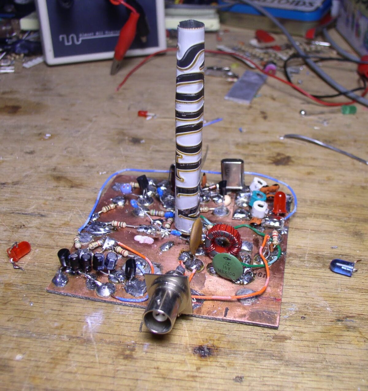
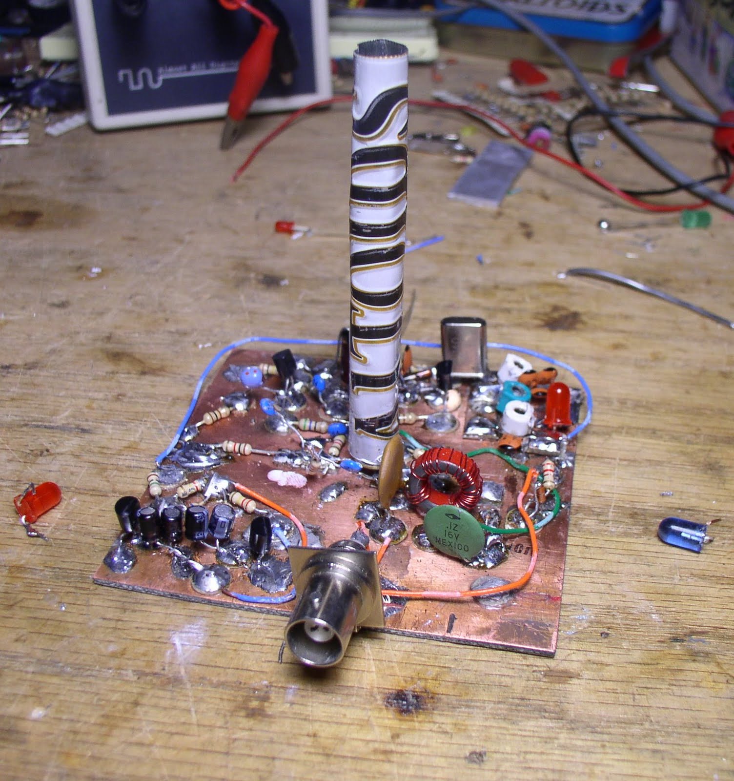 Hey, check out the Altoids heat sink for the PA in my little 30 meter MEPT rig. Is this a new use for our beloved Altoids tins? I like the smoke-stack look.