IF Selection — Which Filter for the New Rig?

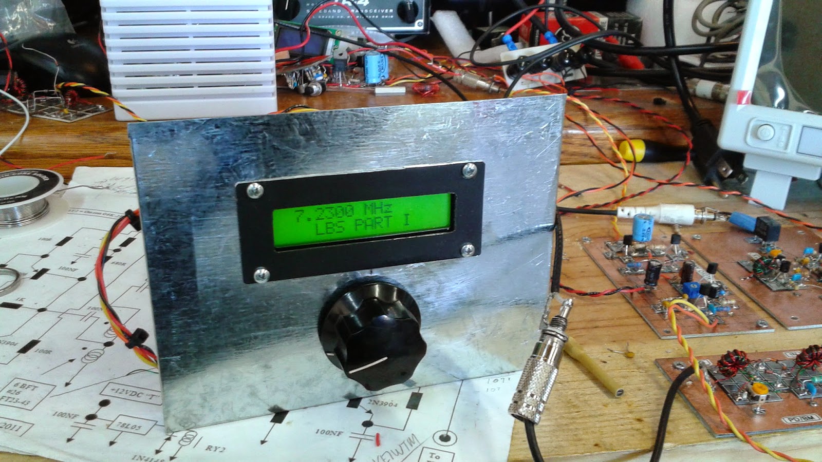
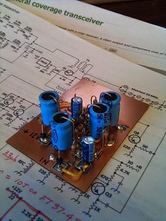
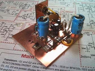
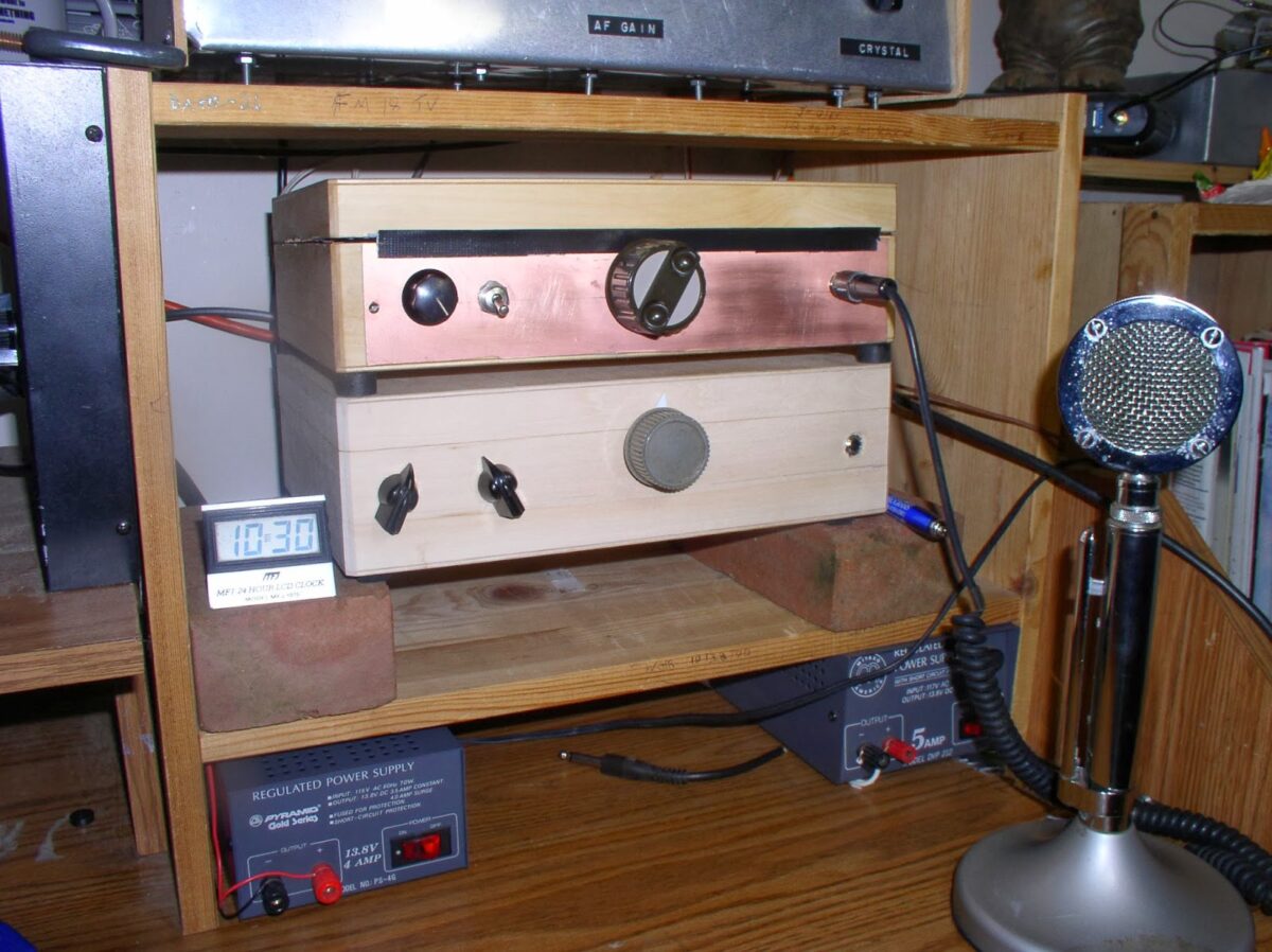
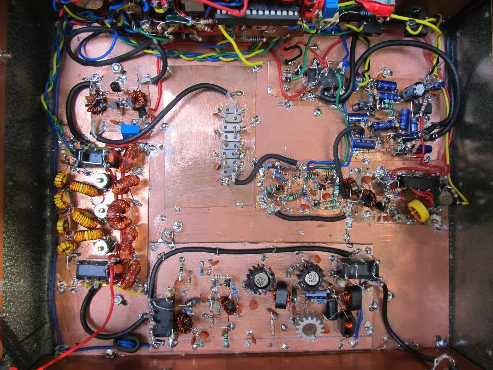
With some prodding from Pete Juliano, I am moving forward on my next transceiver. Same wood box enclosure (with copper flashing), but this time I am greatly relaxing some of the radical fundamentalist restrictions: Chips will be allowed. VFOs and VXOs will be replaced by an Si5351. Filters will not have to be homebrew. Pete has been putting his CNC machine to use and making me some nice boards with isolation pads already milled in. Oh, the luxury!

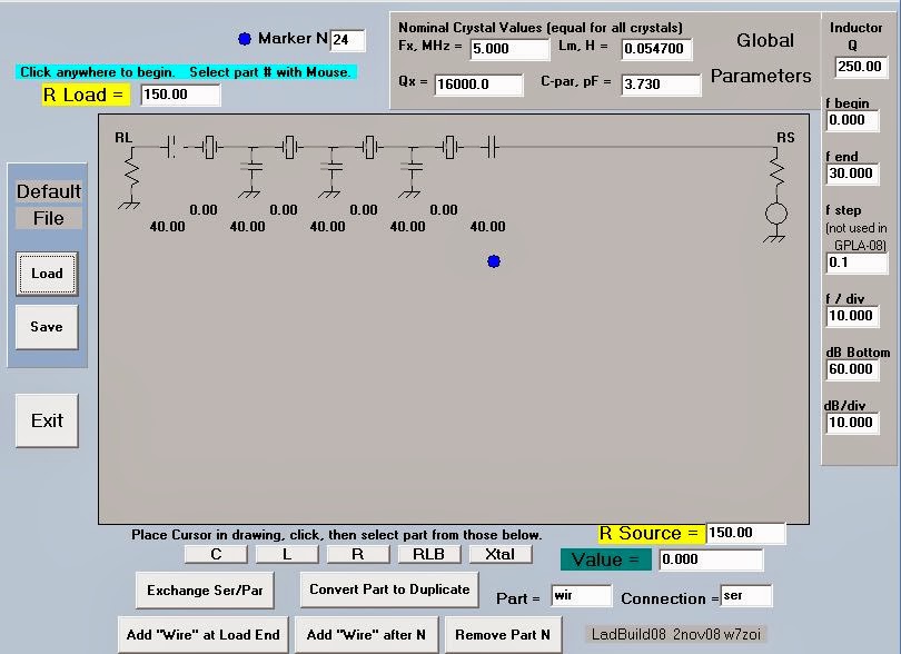
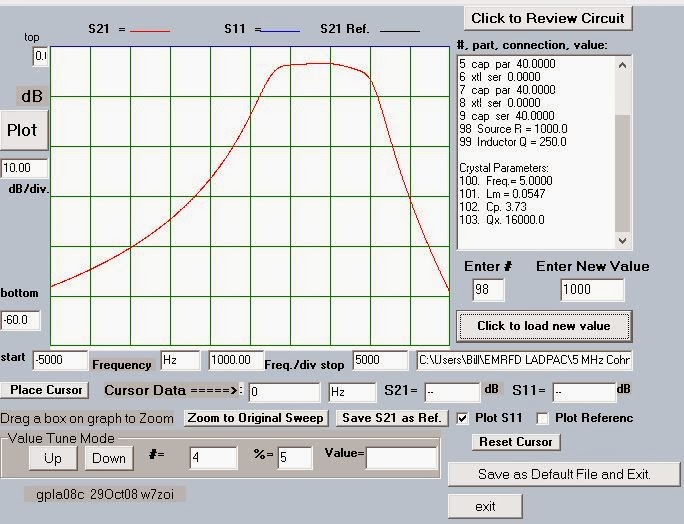
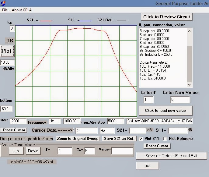
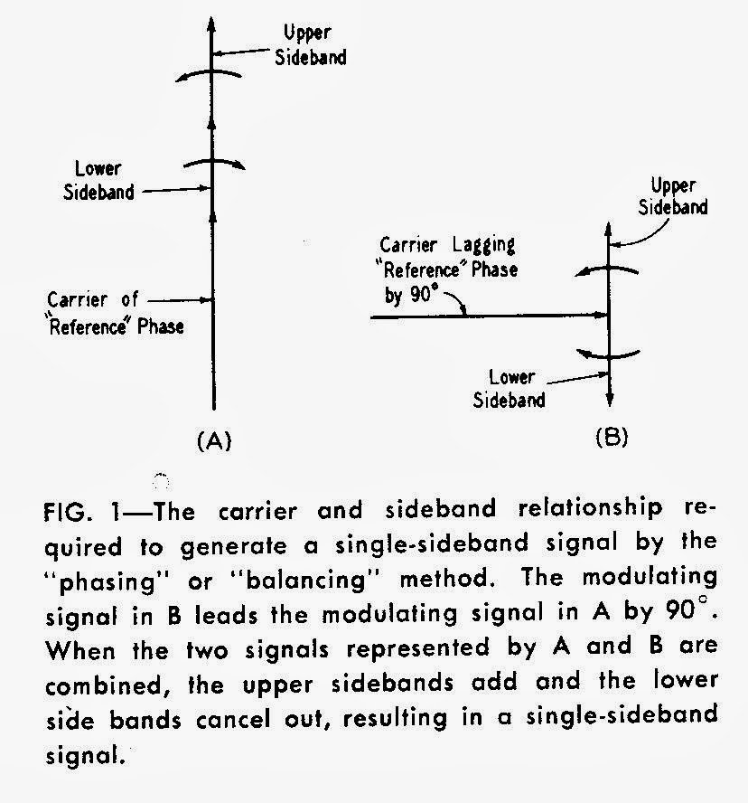
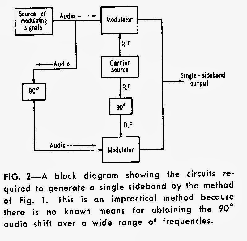
I am going to use the Termination Insensitive Amplifiers designed by Wes Hayward and Bob Kopski back in 2009. These are especially useful in bilateral type transceivers because they allow you to nail down the termination impedances on the crystal filter IN BOTH DIRECTIONS. That’s is important if you want the same filter shape on both transmit and receive.

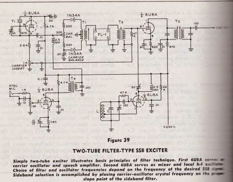
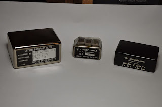
But now, with the trauma of my unfortunate IF selection on the BITX 20/40 (now just 20, sniff…) in mind, what filter should I use on this rig? The three main candidates appear above. The 9 MHz Yaesu filter was given to me some time ago by Steve “Snort Rosin” Smith. The Heath filter (3.395 MHz) and the larger silver one (2.215 MHz) were given to me by Armand Hamel. (Thanks Guys!)

My main band of interest for this rig is 40. But if possible, I’d like to be able to use it on 15 and 12 meters, and maybe even 20 and 17, hopefully without having to change filters.

So what say the gurus? Which one should I use? Or should I put two of them in there, with provisions that would make it easy for me to move from one to the other?

Right now my inclination is to go with the 9 MHz filter, perhaps with the 3.395 MHz filter also available.

Our book: “SolderSmoke — Global Adventures in Wireless Electronics” http://soldersmoke.com/book.htm Our coffee mugs, T-Shirts, bumper stickers: http://www.cafepress.com/SolderSmoke Our Book Store: http://astore.amazon.com/contracross-20

Sideband Inversion


Joel Hallas, W1ZR, (aka “The Doctor”) has an especially good column in QST this month. He takes on a topic that has confused (and re-confused!) many of us: sideband inversion. Simply put, if you have a single sideband signal, and you put it through a mixer, depending on the frequencies involved and on whether you take the sum or the difference product of the mixer, the sideband may or may not get INVERTED! You could start out with an UPPER sideband signal coming out of your sideband generator, then, after you mix it with your VFO (or Si5351!) you end up with a LOWER sideband signal. This can be quite an unpleasant surprise.

Joel gives us a good rule for remembering when this will happen:

“Sideband reversal occurs in mixing only if the signal with the modulation is subtracted from the signal that isn’t modulated.”

Words to live by my friends. Words to live by.

The confusion on this topic often arises in discussions of the old scheme of using a 5 MHz, 9 MHz filter/VFO combination to generate LSB on 75 meters and USB on 20 meters. This is very convenient, but you need to remember Joel’s rule to get this scheme right! If you start out with a sideband generator putting out UPPER sideband at 5 MHz. and mix it with a VFO running at 8.5 — 9.5 MHz, for 20 meters you will take the SUM of the two frequencies. So no sideband inversion. You will be happily on 20 meter USB (the mode used on that band). For 75 meters you will be SUBTRACTING the SIGNAL WITH THE MODULATION (5 MHz) from the SIGNAL WITHOUT THE MODULATION (8.5-9.5 MHz). So, following Joel’s rule you WILL get sideband inversion. Here you will be on 75 meter LOWER sideband (the mode used on that band).

It is easy to get confused on this. I got confused when Steve Smith sent me a 9 MHz filter out of an old Yaesu. I had visions of using the old 9 MHz 5 MHz scheme. But no…. With a 9 MHz sideband generator, you can get on both 75 and 20 with a VFO running at 5 to 5.5 MHz, but you won’t get the nice sideband inversion situation described above because with neither band will you be subtracting the signal with modulation (9 MHz) FROM the signal without modulation (5-5.5 MHz).

It was very nice that Joel admitted to falling victim to this kind of confusion himself in a column he wrote years ago.

Thanks Joel!

Our book: “SolderSmoke — Global Adventures in Wireless Electronics” http://soldersmoke.com/book.htm Our coffee mugs, T-Shirts, bumper stickers: http://www.cafepress.com/SolderSmoke Our Book Store: http://astore.amazon.com/contracross-20

Final Integraton And On-Air Test of the LBS Transceiver (Video) (FB!)

Very nice. A beautiful and educational project from Pete and Ben. I have to start putting “tune switches” in my rigs and ammeters in the bias circuits of my finals.

Our book: “SolderSmoke — Global Adventures in Wireless Electronics” http://soldersmoke.com/book.htm Our coffee mugs, T-Shirts, bumper stickers: http://www.cafepress.com/SolderSmoke Our Book Store: http://astore.amazon.com/contracross-20

Patrick, F6AWY, The SSB Carpenter (Homebrew Hero)

There he is: Patrick, F6AWY, the builder of the beautiful wooden-case SSB transceiver featured here two days ago. Born in 1945, Patrick has been melting solder since age 15. This picture made me think that there must be some connection between string instruments and homebrew genius: Farhan plays guitar. So does Pete Juliano. I think it was Rick Campbell who was strumming the banjo at FDIM… More about Patrick here: http://www.araccma.com/f6awy-p821004


Here is another of Patrick’s projects. He completely rebuilt an old Geloso AM transmitter. Note the markings on the front panel. Signed with a dash of F6AWY panache!
More about this project here:
http://www.araccma.com/emetteur-am-pas-a-pas-avec-f6awy-p820986

Translation tip: Open these pages in Google Chrome. Then, simply RIGHT CLICK on the page and select TRANSLATE TO ENGLISH.

Our book: “SolderSmoke — Global Adventures in Wireless Electronics” http://soldersmoke.com/book.htm Our coffee mugs, T-Shirts, bumper stickers: http://www.cafepress.com/SolderSmoke Our Book Store: http://astore.amazon.com/contracross-20

F6AWY’s Beautiful, Colorful, Wooden Box Transceiver

I was beginning to fear that I might be the only radio amateur in the world operating a wooden-box SSB transceiver. But no! Patrick F6AWY built this MAGNIFICENT rig. Wow, I really like this one. Note the Heathkit S-meter and main tuning knob (I suspect an HW-?? carcass lies somewhere nearby). Note the colorful analog dial and speaker cover, and the classy lime-colored Dymo tape knob labels. This is really an amazing and inspirational piece of work.

The construction details are all here:
http://www.araccma.com/le-tranceiver-en-bois-de-f6awy-p820968
Yes, it is in French, but even if you can’t get Google or Google Chrome to translate it (and that should be possible) you can see what he did through the great pictures and schematic diagrams.

Congratulations Patrick!

Our book: “SolderSmoke — Global Adventures in Wireless Electronics” http://soldersmoke.com/book.htm Our coffee mugs, T-Shirts, bumper stickers: http://www.cafepress.com/SolderSmoke Our Book Store: http://astore.amazon.com/contracross-20

N6ORS’s Long-Delayed SSB Rig

We’ve heard of a few of these “long-delayed” projects. My own 38 year pause in the Herring Aid Five receiver project comes to mind. I like Keith’s idea of a “homebrewers home frequency” but I strongly suspect it would be a very lonely place! Thanks for sending us the pictures of your rig Keith.

Bill:

This project started out about 20 years ago as
a 2 meter FM handheld, then sat in boxes for decades.
Thanks to you and Pete and your podcasts keeping
me company, it morphed into a homebrew 2 meter SSB
rig. It saw ‘firstlight’ last weekend. Of course
I had to operate it without the covers but I made
a short QSO, about 1 mile across town with the wife (kg6oeo).
Homebrewers should pick a “Homebrew home frequency” on
various bands to facilitate homebrew to homebrew contacts.

73,

Keith N6ORS

Our book: “SolderSmoke — Global Adventures in Wireless Electronics” http://soldersmoke.com/book.htm Our coffee mugs, T-Shirts, bumper stickers: http://www.cafepress.com/SolderSmoke Our Book Store: http://astore.amazon.com/contracross-20

Pete and Ben’s “Let’s Build Something” Reference Page

Lots of tribal knowledge here! That’s the direct conversion receiver that forms phase 1 of Pete and Ben’s “Let’s Build Something” project. Arduinos! Si5351s! AD9850s! And it will morph into an SSB transceiver. Check it out:

http://www.jessystems.com/LBS_Detail.html

Our book: “SolderSmoke — Global Adventures in Wireless Electronics” http://soldersmoke.com/book.htm Our coffee mugs, T-Shirts, bumper stickers: http://www.cafepress.com/SolderSmoke Our Book Store: http://astore.amazon.com/contracross-20

Kiwi Lunchbox Sideband: The Tucker Tin Two

Pete Eaton sent us links to an old article from the New Zealand magazine “Break-In.” So many good, simple rigs come to us from New Zealand! Who can forget ZL2BMI’s DSB rig? This one is the work of Fred Johnson ZL2AMJ. It is especially interesting and is in some ways similar to Peter Parker’s “Knobless Wonder.”

It uses the phasing method of sideband generation. No crystal filters in this one. You need TWO balanced modulators. You have a 90 degree phase shift network for the RF (from the carrier oscillator) and a second 90 degree phase shift network for the AF from the mic amplifier. When you combine the signals from the two balanced modulators — viola! — one of the sidebands disappears. The balanced modulators take care of the carrier, and an SSB signal is launched. That is how my old HT-37 works, and similar ideas seem to be at work in modern SDR rigs.

G3TXQ has the complete set of Break-In articles (it includes a VFO):
http://www.karinya.net/g3txq/temp/tucker_tin/

Here is a Canadian article on the rig. A “Tucker Tin” is apparently what the Kiwis call a lunch boxes (shades of Benton Harbor…).


Thanks Pete!

Our book: “SolderSmoke — Global Adventures in Wireless Electronics” http://soldersmoke.com/book.htm Our coffee mugs, T-Shirts, bumper stickers: http://www.cafepress.com/SolderSmoke Our Book Store: http://astore.amazon.com/contracross-20

SSB with Just Two Tubes

Here is the two tube SSB transmitter that Pete was telling me about. This would be a nice companion to the “Mate for the Mighty Midget” receiver that I built a long time ago. Another Benton Harbor Lunchbox may have to be sacrificed…

Our book: “SolderSmoke — Global Adventures in Wireless Electronics” http://soldersmoke.com/book.htm Our coffee mugs, T-Shirts, bumper stickers: http://www.cafepress.com/SolderSmoke Our Book Store: http://astore.amazon.com/contracross-20

A New Look at BITX Carrier Suppression; N6QW IN EMRFD!

Bert, WF7I, was recently struggling to get his BITX 20 going and he asked some good questions about carrier suppression. I realized that I hadn’t really paid much attention to this. Perhaps as a result of my long experience with DSB, I was happy as long as I was able to null out MOST of the carrier.

I fired up the scope and took a look at the output from the BITX 2040 on 40 meters. Here’s the test setup: Coax from the antenna terminal to a 50 ohm resistive load at the Rigol O’scope probe. Just keying the transmitter (no mic connected), carrier was at 980 millivolts rms or about 19 milliwatts. I then connected an AF sig generator into the mic in connector and pumped in some 1000 Hz sine wave. Peak output was 20.7 volts rms, or about 8.6 watts. That puts the carrier about 27 db down. I felt I should be doing better.

I took a look at the shape of my crystal filter and the frequency placement of my carrier oscillator. I noticed that the carrier oscillator freq was fairly close to the bandpass portion of the crystal filter — fairly high up the skirt, only about 9 db below the passband level. I figured that if I just moved that carrier oscillator up around 300 Hz, I would get around 10 db of additional carrier suppression.

Sure enough, with the carrier moved a mere 300 Hz further away from the passband, the residual carrier dropped to 346 millivolts rms, or about 2.4 milliwatts. Now peak output was 20.9 volts rms, or 8.7 watts. 36 db of carrier suppression.

I guess I could do better if I moved the carrier up another little bit, but I like the sound of it now. I may have been able to better if I’d fiddled with the balanced modulator diodes a bit more. But what do you guys think? Should I worry about 2 milliwatts of residual carrier? Heck I once ran a CW rig (W1VD’ VXO 6 watter) that kept the oscillator running on key up, producing about 15 mw of “backwave.” No damage was done, few noticed, no one complained.

Oh yea, is this the way to measure carrier suppression?

—-

While doing all this, I pulled out my trusty copy of EMRFD. The index led me to the balanced modulator section on page 6.56. There I spotted a familiar call: W6JFR!!! That’s Pete Juliano, N6QW! Pete is credited with a mod to the SBL-1 mixer that adds a balance control pot to the device. Wow, actually being IN EMRFD fully confirms Pete’s homebrew guru status.

Our book: “SolderSmoke — Global Adventures in Wireless Electronics” http://soldersmoke.com/book.htm Our coffee mugs, T-Shirts, bumper stickers: http://www.cafepress.com/SolderSmoke Our Book Store: http://astore.amazon.com/contracross-20

SolderSmoke Podcast #162: Part II with Pete Juliano, N6QW

SolderSmoke 162 is now available at http://soldersmoke.com/soldersmoke162.mp3

June 21, 2014
Part II of our interview with Pete Juliano, N6QW

— Bill’s Moxon Monstrosity
— Amplifiers and Exorcisms (See slideshow link below)
— Varactor tuning
— Polivaricon capacitors
— The challenge of building small rigs
— Heat, layout, components and VFO stability
— “No frills” as a building philosophy
— The future of Bill’s Heathkit HW-101

We still have a lot more to talk about. Stay tuned for Part III!

Slideshow of Pete’s RF Amplifiers:
https://onedrive.live.com/?cid=4f1e8c71e0d4f1dc&id=4F1E8C71E0D4F1DC%212640&Bsrc=Photomail&Bpub=SDX.Photos&sff=1&authkey=!AGq3hc4UajARH1s

Our book: “SolderSmoke — Global Adventures in Wireless Electronics” http://soldersmoke.com/book.htm Our coffee mugs, T-Shirts, bumper stickers: http://www.cafepress.com/SolderSmoke Our Book Store: http://astore.amazon.com/contracross-20

El Peregrino (The Pilgrim) from Spain

Eduardo, EA3GHS, sent this to me. It looks like a wonderful bilateral SSB rig for 17 meters.
They said they wanted a “daylight” rig (for a daytime band) because in Spain the religious pilgrims walk all day and are tired at night. Hence 17 for Los Peregrinos!

http://ea3ghs.qrp.cat/peregrino.html

Our book: “SolderSmoke — Global Adventures in Wireless Electronics” http://soldersmoke.com/book.htm Our coffee mugs, T-Shirts, bumper stickers: http://www.cafepress.com/SolderSmoke Our Book Store: http://astore.amazon.com/contracross-20

Harv’s Minima

Good Evening Bill & fellow Solder-smoke friends,
Well, I’m following the pack. I began gathering items for the Minima Transceiver back in March 14. There had been a good bit of strong back-N-forth discussions on the Minima Blog about what works and what doesn’t work. Some circuit refinements had been agreed upon while other were left to individual preferences. So, I decided to just be silent an learn from the experts. As a result, I did several months of observing before I took the plunge. While my efforts are not nearly as aggressive as others, I decided to forge a much slower path to success.
In my own quirky way of doing things, I kitted each module, measured all the parts statically, laid out the components, and finally built & tested each assembly before going to the next.
As a result, the learning’s were great and the performance of each section equal or better than my expectations.
I went the Manhattan Style this time but, I have purchased several sets of Minima PCBs to use in the future. As I see it, there is a lot more solder melting ahead.
Bill, building radios is NOT DEAD yet. That desire to get back to the golden days of home-brewing still lives on.
At the end of the Memorial Weekend, this is my current Minima progress…
· Construction of all 3 Audio Stages now complete (see photos)
· The Microphone Pre-Amp is now awaiting voice testing
· Audio Amplifier and Final Amplifier have been tested together
· The results of audio testing has been superb for all stages thus far
· 3 complete sets of Micro Relays have been order and I’m now awaiting their arrival
· 24 – various ferrite and powered iron cores arrived several weeks ago, these are the heart of the front-end RX/TX stages
· 100 – 20 Mhz. crystals have arrived and await characterization
· 25 – 8” Male to Male SMA Cables have arrived this weekend, will need to order 15 – 4” Male to Male SMA Cable Assemblies next
· 5 – 12” X 15” Copper Clad Boards have arrived this weekend
· 25 –J310 N-channel J RF Power FETs were ordered and arrived this weekend, these are used in the Mixer Stage

Final Audio Stage
Audio Amplifier Stage

Microphone Pre-Amplifier Stage (see microphone connector mounted at rear)
I’m ready to begin kitting the Side Tone Oscillator and RX/TX Relay Stages.
The largest and most intense modules are yet to be tackled.
The Bi-Directional Amplifier has 34 parts alone. So far I have installed over 40 parts in the three modules I’ve completed…
I realize it is just a start but, I’m motivated to see this one project through to completion.
73’s & Happy Soldering
Harv -=WA3EIB=-
Albuquerque, NM.

Our book: “SolderSmoke — Global Adventures in Wireless Electronics” http://soldersmoke.com/book.htm Our coffee mugs, T-Shirts, bumper stickers: http://www.cafepress.com/SolderSmoke Our Book Store: http://astore.amazon.com/contracross-20

SolderSmoke Podcast #161: Homebrew SSB: An Interview with Pete Juliano, N6QW

SolderSmoke Podcast #161 is available:

http://soldersmoke.com/soldersmoke161.mp3

26 May 2013

Homebrew Single Sideband — An Interview with Pete Juliano, N6QW

— Pete’s background: 55 years in radio. Boatanchors AND Arduinos. 40673 Mosfets. Guitar!
— A personal transition from CW to phone.
— The importance of passing on “tribal knowledge.”
— What you need: A library, tools, test gear and a junque box.
— A new word in the homebrew lexicon: Pete explains “noodling.”
— One stage at a time!
— The attractiveness of standard circuit blocks (that work!)
— The importance of IF selection.
— Building your own crystal filters is easier than ever.
— Thinking (early) about the enclosure.
–VFOs, VXOs, and (gasp) Direct Digital Synthesis

Thanks Pete!

Pete’s Web Site: http://www.jessystems.com/

Pete’s YouTube Channel:
https://www.youtube.com/channel/UC4_ft4-oTdCMlWlL4XXHScg/videos


Our book: “SolderSmoke — Global Adventures in Wireless Electronics” http://soldersmoke.com/book.htm Our coffee mugs, T-Shirts, bumper stickers: http://www.cafepress.com/SolderSmoke Our Book Store: http://astore.amazon.com/contracross-20

BITX 17 Build Update: More Filter Maintenance

Having had great success in straightening out the 11 MHz filter in my BITX 2040 (scroll down for details), today I decided to see what I could do with the filter in my 17 meter BITX (four 5 MHz crystals in Cohn MIN LOSS configuration, with 40 pf caps all around). The key to my success in all this has been the filter programs that came with EMRFD. After characterizing my crystals with the G3UUR method, I plugged the values into LADBUILD 8, then took a look at the expected results. As you can see from the image above the predictions were not pretty. Yuck. Lots of ripple and lots of insertion loss.

I went into the rig and using my DDS sig generator and my RIGOL ‘scope, measured actual performance. It looked worse than the prediction (part of the worsening is a difference in vertical scale):

LADBUILD lets you play around with the values of the components in the filters. I know that ripple is usually related to an impedance mismatch. So in LADBUILD I experimented (virtually) with different impedance values at the end. I noticed that at about 1000 ohms, the ripple and insertion loss got better:

So I went and built two broadband toroidal transformers. 4 turns primary with 12 turns secondary (1:9 Z). I’m assuming that the BITX has around 150 ohms at either end of the filter. That would put about 1350 ohms at the ends of the filter.

Here are the results:

Much better.

Our book: “SolderSmoke — Global Adventures in Wireless Electronics” http://soldersmoke.com/book.htm Our coffee mugs, T-Shirts, bumper stickers: http://www.cafepress.com/SolderSmoke Our Book Store: http://astore.amazon.com/contracross-20

BITX 2040 Build Update #10 : Fixing my Filter

That dip on the high side of the passband was bothering me. The GPLA crystal design program predicted it, and indeed, when I measured the performance of the actual filter, there it was. The rig was working fine — the receiver sounded fine and everyone tells me that it sounds great on transmit. But still, it bothered me.

So I started working out with the various crystal filter software packages.

This filter was — sort of — a Cohn Min-loss filter, but I had built it with four crystals and three shunt caps (80 pf each) and no series caps at the input/output. This morning I decided to see what would happen if I put the series caps in there. Here is what Wes’s GPLA predicted:

Wow, that looked a lot nicer. And the 150 ohm terminations seemed to be just about perfect for the BITX design — no need for impedance transformation. I heated up the soldering iron and searched the junkbox for suitable caps (I found 2 82 pf caps — close enough).

Here is what the results looked like (I didn’t measure insertion loss so the top of the curve is just the peak of the response curve).


Exactly as predicted! Thanks Wes! And thanks to Farhan for encouraging me to characterize my crystals and to use the available software

Now I have to go back and de-ripple the 5 MHz filter in my BITX 17.

Our book: “SolderSmoke — Global Adventures in Wireless Electronics” http://soldersmoke.com/book.htm Our coffee mugs, T-Shirts, bumper stickers: http://www.cafepress.com/SolderSmoke Our Book Store: http://astore.amazon.com/contracross-20

BITX 2040 Build Update #9: On-the-air Observations

The BITX 2040 has moved from the bench to the operating position and is producing a steady stream of contacts on 20 and 40 meters. In the picture above it is the rig with the copper-clad front panel (the BITX 17 is below it). It has already crossed the pond on both bands.

Some observations:

I get significantly more power out on 40 than on 20: about 7.2 watts PEP on 40 and about 4.4 watts PEP on 20. I saw a QST article that showed similar frequency/power out variations from IRF510 amps. But I notice I get more power out from my 17 meter rig. On that rig I am using trifilar (9:1 Z) transformer instead of the standard BITX bifilars.

My 40 meter receiver is LOUD. Too much AF out. I am not used to having this problem! On this rig I am using the same discrete component 2n3904 2n3906 transformer-less circuit that I used in the BITX 17. But AF out on 40 was so loud that I had to go back and add 20 k ohms to the top of the volume control pot. I didn’t have this problem with the 17 meter rig, and I didn’t have it on 20 with this rig. Any ideas why this rig would be so loud on 40?

I still want to go in and fine tune the crystal filters in both rigs. I am studying the various software packages out there (especially Wes’s LADPAC). I hope to get rid of the ripple.

In most of my contacts with these rigs, I end up describing the circuit and its Indian origins. Most people are really fascinated. Yesterday W1IDL in Michigan suggested that I contact my Indian friends and get some assistance in making some Hindi or Urdu labels for the rig and the controls. I think that is a very cool idea.

Our book: “SolderSmoke — Global Adventures in Wireless Electronics” http://soldersmoke.com/book.htm Our coffee mugs, T-Shirts, bumper stickers: http://www.cafepress.com/SolderSmoke Our Book Store: http://astore.amazon.com/contracross-20

Farhan’s New Design: A General Coverage Transceiver: The Minima!

The homebrew phone QRP community has been waiting anxiously for the unveiling of Farhan’s new design: The Minima. It is a general coverage transceiver with many innovative circuit features. It has an Arduino in it and an Si570. Farhan’s write up of the design process and the construction of the prototypes is really interesting.

http://www.phonestack.com/farhan/minima.html

I’ve built FOUR JBOTs and TWO BITXs. I even built Farhan’s Subway Sandwich Straw signal generator. So even though I’ve been trying to keep my rigs all discrete, I know I will build this one too.

Three cheers for Ashhar Farhan! Viva La Minima!

Our book: “SolderSmoke — Global Adventures in Wireless Electronics” http://soldersmoke.com/book.htm Our coffee mugs, T-Shirts, bumper stickers: http://www.cafepress.com/SolderSmoke Our Book Store: http://astore.amazon.com/contracross-20

SolderSmoke Podcast #157: Peter Parker on Phasing Rigs

SolderSmoke Podcast #157 is available for download.
http://soldersmoke.com/soldersmoke157.mp3

December 27, 2013

— Santa Report: Rigol Scope at SolderSmoke HQ. Kites at VK3YE.
— Project updates: Bill’s BITX 40/20 build.
— Peter finishing up BITX40 (in a big box)
— BITX 17 (5 watts SSB) works JA, ZD7, ZS!
— The mystery, elegance, and gentleness of phasing SSB
— Phasing explained in 1970 ARRL SSB book
— Phasing SSB: From Hallicrafters HT-37 to SDR
— The SP5AHT Phasing Rig
— I & Q for you: The Binaural Experience
— Direct Conversion receivers and Software Defined Radios
— Simple DC receivers plugging into sound cards
— The joy of receiver building
— 144 MHz aircraft bounce (Melbourne to Sydney)
— VHF Across The Great Australian Bight

HAPPY NEW YEAR TO ALL!

Our book: “SolderSmoke — Global Adventures in Wireless Electronics” http://soldersmoke.com/book.htm Our coffee mugs, T-Shirts, bumper stickers: http://www.cafepress.com/SolderSmoke Our Book Store: http://astore.amazon.com/contracross-20