
Peter VK3YE sent me the link to this amazing site. Wow, Paul VK3HN does great work, both with the homebrew rigs and in describing his work on them. Check it out:
https://vk3hn.wordpress.com/2016/10/25/summit-prowler-one-a-homebrew-7mhz-ssb-qrp-transceiver-for-sota/
Great stuff. Thanks Peter! Thanks Paul!
Category: SSB
HB2HB! KW4KD and N2CQR (video)
A couple weeks ago I ran into Jim KW4KD on 40 meter SSB. Jim is in Chattanooga, Tennessee. He was running a modern “black box” rig, but he mentioned that he had on the shelf two complete homebrew stations, one of which was for 40 meter SSB. He hadn’t used this gear in 40 years. I encouraged him to blow the dust off and get it on the air. Yesterday, Jim did just that. We met up on 40, first at 1730 local (my time) and again at 1930. Excellent! Another HB2HB contact. Check out the video (above). Thanks Jim.
If you run into someone who mentions having some old homebrew gear, encourage them to blow the dust off and get it on the air.
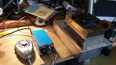
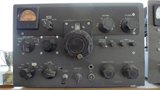
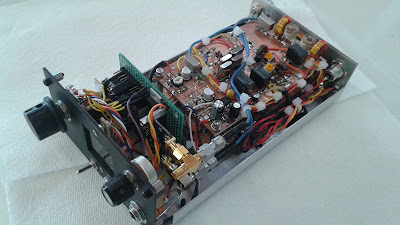
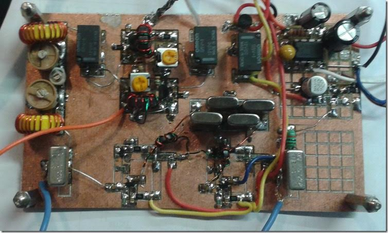
Jim’s SSB rig:
Blowing the Dust Off of KW4KD’s Homebrew Station from the 1970s
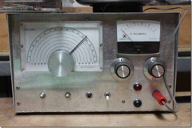 |
| KW4KD CW TRANSMITTER |
I got on 40 meter SSB over the weekend and spoke to Jim KW4KD. He was on a modern commercial rig, but then he told me he had some homebrew gear on his shelf… Wow, it is magnificent. A complete CW station (with homebrew keyer) AND an SSB rig. I immediately launched a campaign to get Jim to fire that gear up and to provide opportunities for more HB2HB contacts. Here is his description of the equipment:
Hi Bill,
It was a blast to get to chat with you too.
Just listening to the audio on this end, I can tell you’ve put a lot of time and effort into getting what you have there up and running.
Never once touched the dial on this end. So your radio gets a A+ for stability too.
Read your Bio on QRZ and sounds like you’ve been a few places, and seen a few things, and that unto itself would make a great contact . But for me, the fact that you are out there building, and I ‘m getting to hear the fruits of your efforts, is ham radio at its best.
Attached are pictures of the gear that made up my station back in the 70’s.
FWIW: At that time my call was WB4YQC.
(But for the record, these shots were taken today.)
In those days I had two setups (Both on 40 mtrs).
A CW station, using separate Xmtr & Rcvr, And a SSB xcvr.
By themselves the CW xmtr ran 8 to 10 watts, and the SSB unit probably hit 5 Watts peak (on a good day).
Like you, I had a separate linear. But in my case I used a pair of 6DQ5’s (TV Sweep tubes) that would run about 180 watts input, (Nothing Solid State, that I could afford, could make that kind of power back in then). The linear is still here, but stashed away in a closet somewhere, so not shown in today’s set of pictures.
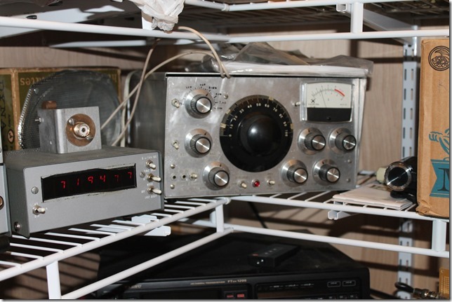
As an Add-On for the SSB unit, I built a Frequency Counter, and used it as a digital dial.
The counter is unique in that it supports two inputs (one for the VFO, and the other for the Xtal BFO). In the 2 input mode, the counter is an UP/Down counter.
The Xcvr’s BFO runs at 9Mhz, while the VFO runs at ~2Mhz. So the counter counts up on one pass, and then down on the 2nd. At the end of the 2nd pass, it updates the Display with the final tally. (i.e, the effective TX/RX freq)
The cases for the Xmtr & Xcvr were designed by me, but were built by a friend who had access to a metal brake. Internally none of the units are especially pretty, as the were always works in progress.
I’ll have to dust off the linear. Its been at least 40 yrs since its seen AC.. Not sure what kind of shape the electrolytics are in.
Probably need to apply power slowly. I’ll see if I can round up an Autotransformer.
As far as posting on your blog, if you think it will encourage others, I’d be flattered if you did;
However, before anybody asks, (assuming that they might) there’re no schematics. Everything was built from sketches made on envelopes and napkins, which have long since disappeared. And even if they did exist, not sure today that you’d be able to find some of the ICs & transistors that the units use.
Again, it was my pleasure to catch you on the band today, & look forward to getting to hear you again.
73 Jim (KW4KD)
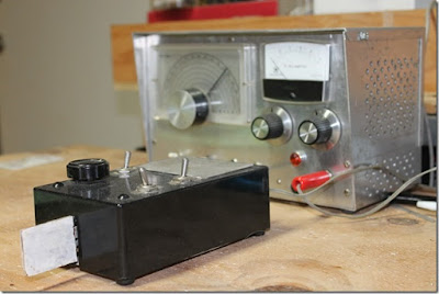 |
| KW4KD CW TRANSMITTER WITH HB KEYER |
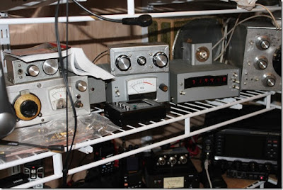 |
| 40 Meter CW receiver on Left |
|
| 40 meter SSB transceiver with freq counter |
Cool, Blue, and Homebrew! Pete Juliano’s Tiny SSB Rig
Blue is the new Black! I think some smart paint manufacturer should put a trademark on “Juliano Blue.”
Check out Pete’s latest efforts:
http://n6qw.blogspot.com/2016/07/small-radio-big-signal.html
The Solder Is Smoking at N6QW!
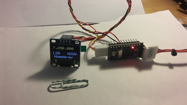
It is very good to see the solder flowing again in the Newbury Park Laboratories of Pete Juliano, N6QW. Check out that postage stamp-sized display.
More details on Pete’s newest rig can be found on his blog:
http://n6qw.blogspot.com/2016/05/a-new-ssb-transceiver-from-n6qw-with.html
Farhan’s Cool BITX 40 (video)
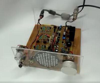
I especially like the wood base and the transparent front panel. But we have to send Farhan a D-104!
Check out the video of this rig in action:
Farhan posted:
The BITX40 has a redesigned crystal filter at 12 MHz that contributes to a very clear signal. Note the clarity on SSB and the absence of noise due to the three poles of filtering. This was charminar net on May 2, 2016. I couldn’t break-in. Probably because the tiny plug mounted mic was too far away from my mouth.
Be afraid! Be VERY afraid! Digital Audio on 20 Meters (video)
Here is a very interesting comparison between digital audio, and plain old SSB audio (from a Collins rig!).
I don’t know. I may be prejudiced here, but that digi audio just doesn’t sound too good to me. And I ask myself: “How could it?” They are restricting the transmit bandwidth to 1.2 kHz. Can the error correcting elements of the software help them get around the bandwidth limits of Shannon’s communications theory?
The digi audio sounds quite robotic to me. Even Siri sounds better. Is this because — as the receiving station noted — they were only getting “80 percent decode”? Would the digi audio have sounded better if signal strength had been better?
Again, I don’t know. But remember. I am a Ludite (with a single d — the ORIGINAL spelling!).
N3FJZ’s New Blog and Impressive Rigs (and a Bandscan!)
Rick N3FJZ and his Lakeside direct conversion receiver bolstered my spirits when I was getting some harshly critical reviews of my signal on 40 meters a while back. Rick happened to pick me up with his homebrew receiver. The Radio Gods seemed to be trying to balance things out. There is a LOT of radio mojo in Rick’s Lakeside receiver. Not only does it eschew digital synthesis of the VFO signal, it goes a step further and uses a permeability tuned oscillator — very cool. The component and material sourcing adds more luster to the rig. Rick writes: “A lot of the components used to construct the LS-40 were harvested from discarded consumer electronics I collected back in the 1980’s. The base substrate material for the Manhattan style construction, as well as the RF tight enclosure for the PTO, is made from a flattened out tin plated food can. All components are discrete; i.e. no IC’s or CPU’s.”
Rick has launched a blog. He has some amazing stuff on it. Be sure to check out his ZX-SSB rig. Amazingly detailed documentation Rick! Thanks.
Find Rick’s Blog here:
http://www.remmepark.com/circuit6040/
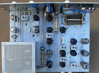
Octalmania — KG7TR’s Amazing Thermatron Rigs
Grayson in Turkey alerted us to Mike’s homebrew rigs:
Bill, Pete:
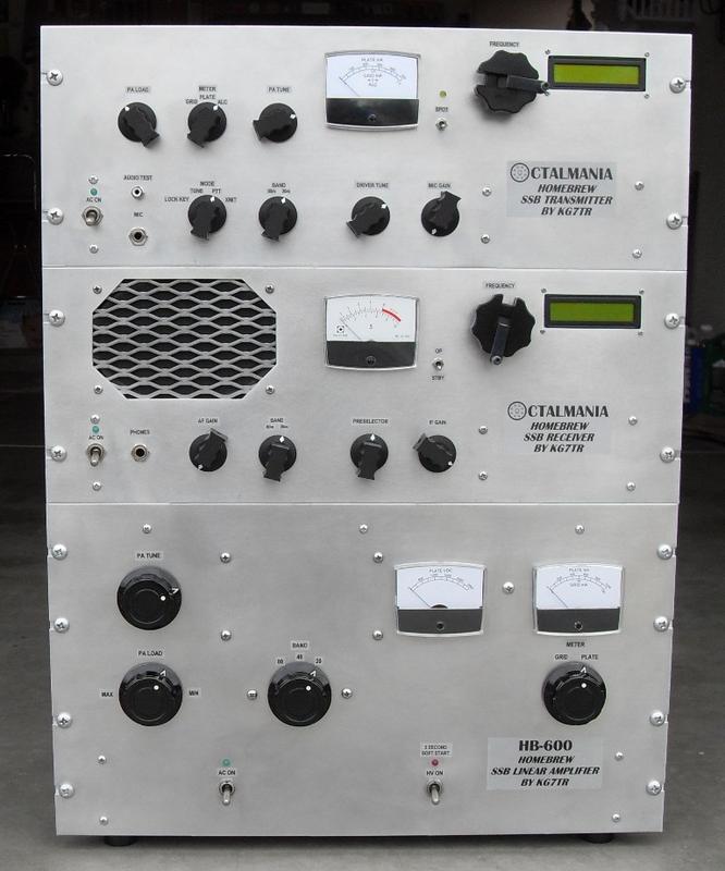
I had to pass along photos of the latest work of Mike Bohn, KG7TR. Mike is a long time thermatron home brewer, having built several SSB receivers and transmitters. He is famous for his “octal mania” designs that only use octal tubes. His present SSB transceiver is no exception. Some of his work is shown in my HSD book.
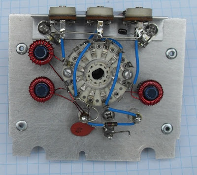
This is SERIOUS homebrewing, a work of art. According to Mike he spent “six months of pretty much full time work (6-7 hours per day, 6-7 days a week) to get the radio to the state shown in the pictures. Probably 750 to 1,000 hours. I retired in January and this was one of my bucket list projects.”
This is way more time than most of us who still work ever hope to devote to a homebrew project, but it gives me hope. Someday we will hopefully retire.
This is a 80,40,20 meter rig with a pair of 6146’s on the output. Tuned the good old fashion way with 5-5.5 Mc L/C colitis oscillator. It does have an IC freq counter as the frequency display.
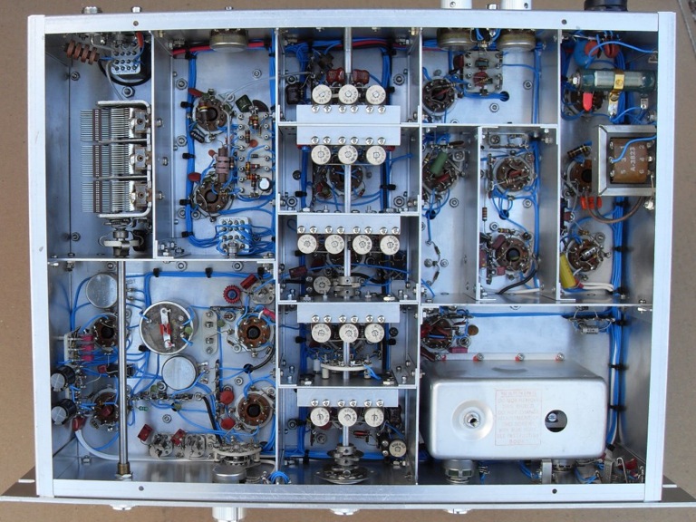
Even though the metal work looks like it was done in a well equipped machine shop, Mike says “The sheet metal work was pretty onerous. I don’t have the tools to shear metal or make right angle bends, so everything had to be done with a jig saw, angle stock and files.” This also give me hope, but I have a hard time believing he doesn’t have a numerically controlled, laser mill!
Thought you would like to see some super nice work. Certainly “raises the bar”
73
Grayson
TA2ZGE – Ankara, Turkey
KJ7UM
Follow the Hollow-State Design Blog
Pete’s STUNNED reaction:
Hi Bill,
Thanks –you have ruined my day –almost wants me to take all my radios to the scrap heap. Those are not radios but works of art. Lots of man hours in those projects and more amazing is finding many of the parts – the thermatrons are easy to find –it’s the other stuff that is nearly unobtanium.
Pete
Much More Here: http://qrz.com/db/KG7TR
Unfazed! Fight HISS-teria! Give the Si5351 a Chance.

Thanks to all who have contributed to our discussion of phase noise and the Si5351 chip. Let me throw out some ideas — some technical, others philosophical.
1) We may be worrying about this too much. In all of the homebrew or kit rigs we’ve built over the years, I never recall much concern about the phase noise specs of the LC or crystal oscillator circuit that we were using. What were the phase noise stats on a Heath VF-1? How about the phase noise stats for the little Hartley oscillator in those DC receivers we made? No one even checked. Our rigs usually worked just fine. We would have noticed if they were extremely noisy, but if they were good enough, we left well enough alone. It doesn’t really make much sense for us to now be suddenly very concerned about the phase noise stats of the various DDS and PLL chips that are replacing those LC and crystal circuits, especially when the measurements show that they are usually in the same range as our old familiar oscillators.
2) The perfect can be the enemy of the good, and the “good enough.” We have a long tradition in ham radio of tolerating less-than-perfect or less-than-optimum parts. Remember, the NE-602 has some shortcomings, but we use it. We use it a lot. The IRF-510 wasn’t even designed to be an RF amplifiers, but we have pressed it into service for our PAs.
3) We should be willing to give a new part a try, and we should be pleased if it proves useful. We should be wary of untested claims re the unsuitability of a component. We have to avoid the “works in practice, but not in theory” situation. If something works well, doesn’t create additional QRM, is inexpensive, and fosters experimentation and homebrewing, we should be happy about being able to use it.
4) All electronic components — not just the Si5351! — produce noise. Resistors produce noise. Look at this:
” We can infer… that if we install phase-quiet oscillators in transmitter and receiver, we ought to be able to tune our receiver to a frequency closely adjacent to a very strong signal from the transmitter without encountering anything like phase-noise hiss. Yet, after an exhaustive phase-noise cleanup at transmitting and receiving sites, we test our communication system only to discover that the transmitter still emits broadband hiss! The culprit is transmitted amplifier noise. Just about every modern transmitter or transceiver consists of a high-gain, linear amplifier strip that amplifies the low-level output of oscillators, mixers and phase-locked loops to hundreds of watts or a few kilowatts. Because amplifier circuitry is not perfectly quiet, the output of the transmitter contains noise (hiss) in addition to the amplified signal. Transmitted along with the desired signal, this hiss can degrade the noise floor of nearby receivers-just as transmitted phase noise can. Where does amplifier noise come from? Thermal noise, for one thing. Electronic components operated at temperatures greater than absolute zero generate random electrical noise. This noise is broadband in nature. Greatly amplified in an audio amplifier-or greatly amplified in a radio transmitter, transmitted as broadband radio noise, received and converted to audio-it sounds like hiss. Random variations in electron flow within active amplifier components (transistors and vacuum tubes) are another source of amplifier noise. Transmitted as broadband radio noise, received and converted to audio, it also sounds like hiss.” Source: http://www.robkalmeijer.nl/techniek/electronica/radiotechniek/hambladen/qst/1988/03/page14/index.html
5) It seems that whenever a new technology or part comes along there will be those who issue dire warnings about how we can’t or shouldn’t use it. When transistors came along, there were those who said that hams shouldn’t homebrew with them because — it was argued — without spectrum analyzers we couldn’t possibly come up with spectrally pure signals.
6) We have to be careful lest this obsession with perfection and extremely high tech standards be used as a rationale for not homebrewing, or (much worse) as an argument against homebrew rigs on the ham bands. There is a bit of this going around. Get on 40 meters with rig that drifts a bit or that is not “on frequency” to within 10 Hz and you will find out what I mean.
7) The Si5351 is a good part for our purposes. It does something new and VERY useful for us: It can put out BOTH our VFO and BFO frequencies. It makes it much easier for us to change bands and-or switch between USB and LSB. Its phase noise figures are fine. LA3PNA (citing measurements by KE5FX) notes: “The phase noise of the Si5351 is around -130dBc/Hz at 10KHz. This is quite decent, If compared to a Hartley or Collpits you would see little or no difference. Some of my measurements of published free running oscilators show phase noise in the -110dBc/Hz range!”
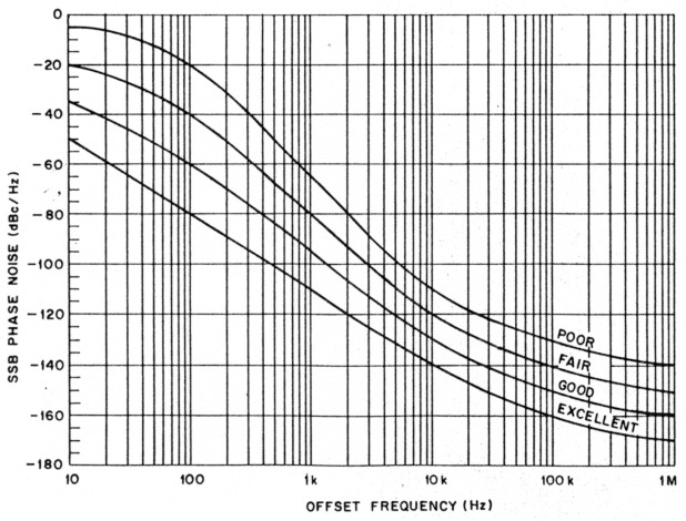
-130 dBc/Hz at 10 kHz puts this part on the “good” curve of this chart. From (http://www.robkalmeijer.nl/techniek/electronica/radiotechniek/hambladen/qst/1988/03/page14/index.html
We should give this little chip a chance! Give it a try!
Our book: “SolderSmoke — Global Adventures in Wireless Electronics” http://soldersmoke.com/book.htm Our coffee mugs, T-Shirts, bumper stickers: http://www.cafepress.com/SolderSmoke Our Book Store: http://astore.amazon.com/contracross-20
Si5351 Phase Noise? A Tale of 3 Oscillators

Si5351 at 16 MHz
There is still a lot of talk about the supposedly horrible phase noise of the Si5351 chip. In a recent episode of a popular (and very good!) podcast about homebrewing, the podcasters talked about this in the context of some megawatt AM shortwave broadcast stations that had oscillator phase noise problems and were wiping out large portions of the HF spectrum. I don’t think those stations were running Si5351s, but the listener was left with the impression that these handy little chips are very noisy with lots of spurs and will inevitably produce horrible dirty, spectrally impure signals.
This has not been our experience. Following Pete’s lead, several of us are using the Si5351 to generate both VFO and BFO signals in our transceivers, with good results. The receivers sound very good and we have not heard complaints of “broad” or “noisy” transmitted signals.
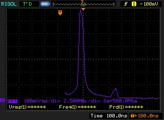
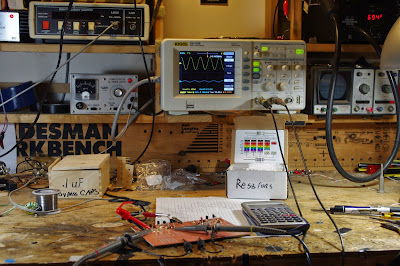
I decided to dig into this a bit. This was also an excuse for me to use the FFT and screen capture features on my Rigol ‘scope.
I now have THREE BITX transceivers in the shack. My BITX17 uses a VXO at round 23 MHz (IF at 5 MHz)/ My BITX20 uses a classic LC VFO running around 3.5 MHz (IF at 11 MHz). Finally, my BITX40 (DIGI-TIA) uses the dreaded and much reviled Si5351 running at around 16 MHz (IF at 9 MHz). I thought that these three rigs would provide a good opportunity to test the scurrilous claims about the Si5351.
As a simple first test, I put my Rigol scope in FFT mode and just put the probe at the VFO Mixer’s LO input. The screenshot above is the FFT for the Si5351. It looks pretty clean to me. The ‘scope is looking at 15 Mhz above and below the VFO signal.

VFO at 3.5 MHz
Next I measured the output of the BITX20 VFO at the same point (input to the VFO mixer). (I had to change the vertical range, but the horizontal was unchanged.) Here you can see the second harmonic (just because at this low freq it is within the freq range setting of the ‘scope). It doesn’t look much different than the Si5351.

VXO at 23 MHz
Finally, here is the BITX17 VXO at 23 MHz, again at the input to the VFO mixer. It looks remarkably similar to the Si5351, don’t you think?
More on this to come. The ARRL Handbook (2002) has a good discussion on phase noise. I am digging into this and hope to do some more tests. For now, I think we should reserve judgment on the utility (for us) of the Si5351.
Our book: “SolderSmoke — Global Adventures in Wireless Electronics” http://soldersmoke.com/book.htm Our coffee mugs, T-Shirts, bumper stickers: http://www.cafepress.com/SolderSmoke Our Book Store: http://astore.amazon.com/contracross-20
The KJURKN Receiver (video)
Shell, WA6KJN, has built some really cool homebrew rigs. And an airplane.
On his QRZ page Shell writes: “I have saved all my old homebrew gear. This is a tube SSB exciter using a pair of 6146’s in the final. It has a Collins mechanical filter. Built in the 70’s. It had a matching receiver also with a mechanical filter in the I.F.”
Check out the QRZ page for meore inspiration (and some good ideas on towers):
https://www.qrz.com/db/WA6KJN/
Our book: “SolderSmoke — Global Adventures in Wireless Electronics” http://soldersmoke.com/book.htm Our coffee mugs, T-Shirts, bumper stickers: http://www.cafepress.com/SolderSmoke Our Book Store: http://astore.amazon.com/contracross-20
Mikele’s Croatian Belthorn Transceiver
Mikele’s rig is a real “International Brotherhood of Electronic Wizards” kind of project. The Belthorn design is out of England. N6QW has added a lot of California influence. The Nokia screen adds a bit of Finland. And of course Mikele’s excellent construction makes this a profoundly Croatian rig.
We love seeing rigs in their “out in the open ” phase. Thanks Mikele!
Our book: “SolderSmoke — Global Adventures in Wireless Electronics” http://soldersmoke.com/book.htm Our coffee mugs, T-Shirts, bumper stickers: http://www.cafepress.com/SolderSmoke Our Book Store: http://astore.amazon.com/contracross-20
Some HB SSB History -The Belthorn Story

The Eden Valley, Cumbria, England
Hello Bill,
As per your discussion with Pete in #177 I can indeed confirm that the correct pronunciation of Belthorn is “Bell-Thorn,” like Bell and Thorn concatenated. I named the design the “Belthorn SSB IF Module” in honour of the village I was living in at the time I developed it. I wanted to put the village on the map and in doing so leave my mark.
The design was published as a two part article in RadCom May/June 2000 intended to offer an alternative to the Plessey SL600/1600 IF strips of the late 70s early 80s. These integrated designs opened up simple SSB construction to many but by the mid 80’s sources of SL600/1600 ICs had all but dried up. I thought that a new design using readily available parts would be worth developing to offer a simple and repeatable basis for building an SSB transceiver.
From the emails I’ve received over the years it was and still is a popular project with many hundreds if not thousands having been built around the world. When the MC1350 IF amplifier became an endangered species I returned to the drawing board to produce a new version using a home brew diode DBM front end, a simple cascode IF stage and NE/SA612 product detector/modulator. An interesting feature of this was an AGC system based around an 8 pin 12F683 PIC. This new design offered considerable simplification and retained excellent performance. It was christened the “Eden SSB IF Module” after the Eden Valley where I now live in the north of England. It formed part of a transceiver project published on Yahoo Groups (Search for Eden 9). The gentleman who created the Yahoo Groups site mistook my schematic revision number (9) to be part of the name, and so it unwittingly became Eden9!!! Fortunately the NE/SA612 remains in production although should it become obsolete I would probably make things right by bringing out a yet another version of the IF strip, perhaps with a switching mixer. Here are a couple of links from the “old world” to give you a flavour of Belthorn the village and Belthorn the design;
The village website –http://www.belthornvillage.co.uk/ (Note that they’ve just bought a pub!)
The origin of the name “Belthorn” is quite interesting – although of little relevance to radio! Before the industrial revolution the village used to be on a pack horse route. to this day there is a house at the top of the village called “Bell in the Thorn” many years ago this used to be an inn. It’s thought that it takes its name from when a Bell hung in a thorn bush or tree nearby was used to signal when a horse change over was required to carry loads up and down the hill, probably from the mines or quarries on the nearby moors.
The link for the “Eden9” which you may find interesting is; https://groups.yahoo.com/neo/groups/eden9/info There is a power point presentation in the files section which describes the project and which features a section on receiver design. It may be a useful primer for those interested in the design process.
You can still find my original website on the internet archive complete with an introduction to Belthorn the village and a few of my earlier projects here; http://web.archive.org/web/20090316093248/http://g4gxo.cwc.net/
73 Ron G4GXO
Our book: “SolderSmoke — Global Adventures in Wireless Electronics” http://soldersmoke.com/book.htm Our coffee mugs, T-Shirts, bumper stickers: http://www.cafepress.com/SolderSmoke Our Book Store: http://astore.amazon.com/contracross-20
Pete’s LBS II Transceiver
Look at that. That is the work of a master homebrewer. More info and more great pictures here:
http://www.n6qw.com/LBS2.html
Our book: “SolderSmoke — Global Adventures in Wireless Electronics” http://soldersmoke.com/book.htm Our coffee mugs, T-Shirts, bumper stickers: http://www.cafepress.com/SolderSmoke Our Book Store: http://astore.amazon.com/contracross-20
Pete Shrinks the Transceiver (Video)
Pete writes: This video shows the LBS XCVR shrunk down to a mainboard that is 2.5 Inches by 4.5 inches. The board contains the 20 Meter Band Pass Filter, the RxTx Mixer, a TUF-3, two bilateral amplifier stages a 5.185 MHz Homebrew Filter. a TUF-3 PD/BM. The Audio amp stage and the microphone amp. Not built as yet is the bi-directional stage that on receive is the RF amp and on transmit the Tx pre-driver stage. Extensive use of SMD components makes the size reduction possible. The transmit final stages will be on a 2nd board that is stacked on top of the mainboard. An Arduino Pro-Mini does all of the control for the Si5351 VFO/BFO. The final size will be 4X6X2. Oh it also has a color display! http://www.n6qw.com/.
Our book: “SolderSmoke — Global Adventures in Wireless Electronics” http://soldersmoke.com/book.htm Our coffee mugs, T-Shirts, bumper stickers: http://www.cafepress.com/SolderSmoke Our Book Store: http://astore.amazon.com/contracross-20
Another Great Rig (and Video) from Peter Parker VK3YE
Peter Parker has a double dose of The Knack: Not only is he a great rig builder, but he is also a very skilled teacher. His videos provide really excellent descriptions of how he selects, designs, and modifies the stages that make up his magnificent rigs. You can learn a lot from these videos. Thanks Peter.
Our book: “SolderSmoke — Global Adventures in Wireless Electronics” http://soldersmoke.com/book.htm Our coffee mugs, T-Shirts, bumper stickers: http://www.cafepress.com/SolderSmoke Our Book Store: http://astore.amazon.com/contracross-20
Frank Harris and the Nobel Prize for Sideband
A lot of wisdom and good info in this chapter (and in the whole book);
http://www.qrparci.org/wa0itp/chap15.pdf
http://www.wa0itp.com/crystalsetsssb.html
Our book: “SolderSmoke — Global Adventures in Wireless Electronics” http://soldersmoke.com/book.htm Our coffee mugs, T-Shirts, bumper stickers: http://www.cafepress.com/SolderSmoke Our Book Store: http://astore.amazon.com/contracross-20
BITX DIGI-TIA Build Update #1 Building the First 2 TIA Amplifiers
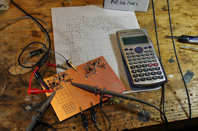
I started building the new transceiver today. I am tentatively calling it the BITX DIGI-TIA. Digi because it will have at its heart an Si5351 for BFO and VFO signal generation, and TIA because it will use Termination Insensitive Amplifiers (TIAs). These TIA amps are designed to present a 50 ohm impedance not matter what impedance you connect to the other end. This is a very useful feature when you are trying to get a certain impedance for a crystal filter in a bidirectional rig — you want the same termination impedances in both directions.
I built the “top” halves of two of the TIAs, using CNC-cut boards given to me by Pete Juliano. Thanks Pete! I like the boards, and I no longer have a thick coating of dried SuperGlue on my fingers.
Both amps seem to be performing very well. Some numbers:
Current draw at 12 V (no signal) 30 ma.
Gain at 9 MHz (no load): Amp 1: 27.2 db Amp 2: 26.5 db.
I then took a 110 ohm load and put it across the output of Amp 1. Gain dropped to 23.9 db (as you’d expect). BUT HERE’S THE GOOD PART: The input voltage from my homebrew sig generator stayed exactly the same. Termination insensitivity.
More on these amps (with a link to Wes’s article) here:
Next I’ll put the 9 MHz filter between these amps and measure the shape of the filter passband.
Our book: “SolderSmoke — Global Adventures in Wireless Electronics” http://soldersmoke.com/book.htm Our coffee mugs, T-Shirts, bumper stickers: http://www.cafepress.com/SolderSmoke Our Book Store: http://astore.amazon.com/contracross-20