WA4GEG’s Beautiful HB Transceiver

http://www.hamradiobug.com/homebrew.html

Pete spotted this. Beautiful work. I noted that Byron hasn’t used the Manhattan style of construction. This makes his work look a lot neater, but it makes it harder to modify and debug the circuitry. On the other hand, OM Byron is obviously so good at this that his circuitry probably doesn’t require any debugging or mods.

The red S-meter and freq counter give it a slightly menacing appearance. Very cool.

“The Black Rose” — Yardley Beers’ 1955 HB SSB Transceiver

I’ve been a fan of Homebrew Hero Yardley Beers W0JF for a long time. Here is a link to previous posts on him: http://soldersmoke.blogspot.com/search?q=Yardley
Yesterday I got a nice e-mail from Boulder Colorado about Yardley’s very early SSB rig. I’m guessing that the 4.7 MHz is a typo — it might have been 3.7 and 14 MHz. FB. Thanks Mike


Bill,
Yardley Beers W0JF moved to Boulder in the early 1950’s to work at the National Bureau of Standards (now NIST) laboratory. There he headed the Time and Frequency Division, which maintains the atomic clock. He later taught at the University of Colorado and Denver University.
About 1955 he homebrewed what, at the time, may have been the only SSB transceiver in the world. It was built with individual transistors (no IC’s in those days) and Yardley had to grind the crystals himself for the filter. He enjoyed naming his radios and this one was “The Black Rose.”
The transceiver ran at 4.7 and 14 MHz. Its 1/2 watt output was fed to a home built amplifier. The transceiver demonstrated the practicality and benefits of SSB in a world where AM was the voice mode.
In the year 2000 Yardley demonstrated this original, old SSB transceiver to the Boulder Amateur Radio Club by using it to make contacts with two club members. Attached to this e-mail are a couple of photos.
73,
Mike W3DIF
Treasurer, Boulder Amateur Radio Club (BARC)

ZL2CTM’s Homebrew Transceiver Project

Wow, Charlie has a lot of very cool ideas in this initial video. Some suggestions:

— With the IRF-510 in the final, beef up the heatsink, and follow Farhan’s lead by including an option for 24 volts on the drain. That would take you up to 20 watts or so (for those who are so inclined).

— Could that Teensy SDR board work at the IF frequency? If so, consider putting it ahead of the crystal filter. This would enable us all to join the Waterfall Signal Purity Police Force.

— I love the OLEDs too, but I found them to be noisy. I minimized the noise with shielding around the OLED and active decoupling on the power line to the AF amplifiers.

More of Charlie’s work here:

https://plus.google.com/107506245856154702088

More on K0EOO’s Amazing Homebrew SSB Rig

Hello Bill,
The rig was my own design based on an article by Guy Gillet, ON5FE, published in QST, Jan 1970. (Editor’s Note: ON5FE’s article also appears in the 1970 edition of the ARRL’s book “Single Sideband for the Radio Amateur.”) His article had some features I wanted and became the guts of the transceiver I finally came up with… The rig took me some 2-4 years to complete mainly because I keep changing circuits and improving performance. For example, I started with a 4 digit counter using nixie tubes and ended up with 7 digit 7 segment LED counter summing the BFO, VFO and HFO. I also later added the keyer and CW audio filter and so on…..
Other than the outer cabinet from LMB, I did all the metal work complements of the metal shop at our lab at CDC’s advanced design lab.

Pictures show bottom with RF bottom plate installed and bottom view of RF section with plate removed. Front panel and picture of top cover open showing the plugin PCB’s. Cannot see the digital counter display board in any of the pictures.
Here are a couple pictures of the old girl. I’ve added a description of the rigs features:

Features:
  • Dual conversion, first IF tunable, second IF fixed
  • RF clipping
  • 7 digit readout of exact operating frequency (digital summation of BFO, VFO and HFO)
  • All solid state except for 6146 and 12BY7 driver.
  • RF gain is 0-60dB step attenuator on input
  • Dual VFO’s for separate receive/transmit or transceiver A/B
  • Modes are USB/LSB/CW
  • Auto zeroing S-Meter
  • Built in VOX and PTT
  • Built in CW keyer and sidetone generator
  • Built in CW audio bandwidth filter
  • Built in Tune mode
  • Built in RF Clipping lever control
  • Built in keying to PTT external amplifier
  • Output signals for SB-610 scope receive signal monitoring
  • Output signal for SB-620 Scanalyzer panadapter
  • Diode T/R switching through out the radio, no relays, totally silent TR switching
Well Bill, you opened Pandora’s box when you asked me for more details, hi, hi… You can almost see the buttons popping off my vest as I reminisced the feature list…
Regards, Dennis, K0EOO


K0EOO: Homebrew SSB in 1974

It is not everyday that you get on 40 meters and run into a guy who has actually built a single sideband transceiver. But that is what happened to me today. I spoke to Dennis, K0EOO. He showed an unusual interest in my BITX DIGI-TIA. He went on to explain that he had done some homebewing himself. In the picture (from 1974), right next to his Vibroplex bug we see his homebrew, 80-10 meter, dual conversion, solid state (except for the 6146 final) SSB transceiver with digital readout. Wow. That’s a beautiful rig.

Off his right shoulder is a homebrew 700 watt amplifier using dual 4CX250s. And behind his left shoulder we see a homebrew tube-type receiver.

Note the look of pride and determination in OM’s eyes. You can just hear him saying it: “Rig here is homebrew.”

More pictures of Dennis and his rigs (including some amazing vintage gear) here:

https://qrz.com/db/K0EOO

http://www.isquare.com/millen/members/k0eoo.htm

http://www.vintagessb.net/k0eoo.htm

Intuitive Repair of a Sony Shortwave Portable

A few years ago my wife got me this nice little Sony ICF-SW7600GR receiver. On the front it proclaims that it is “AM DUAL CONVERSION” and “PLL SYNTHESIZED.” It has a BFO, and a filter of suitable width for SSB. It also has a synchronous detector — it generates an internal carrier that matches the frequency and phase of the carrier being transmitted by the SW broadcast (or ham AM) transmitter. This helps overcome the selective fading that often plagues AM signals. Sony advises switching to USB or LSB once the synchronous generator locks onto the carrier. Pretty cool.

The BFO is the reason I wanted this receiver. And wouldn’t you know, when I dropped it, it landed EXACTLY on the little BFO fine tune control pot. It was as if the Radio Gods disliked all the fancy digi PLL synchronous IC circuitry.

I tried without success to find the value of the destroyed pot. Finally, last week I just decided to have a look in there to see if I could just figure it out.

On the board I could see that the pot only connected at two places, so I figured it would be a varactor circuit on the BFO with one end of the pot to DC and the wiper to the varactor diode. I figured I’d try a 10K pot.

This seems to have been some good radio intuition. It works. I went with a small trimmer because it is less obtrusive and because once I set the BFO in the right spot, I think the de facto channelization of the 40 meter ham band will keep most of the SSB sigs in tune. And the Sony only tunes in 1 kHz increments. If necessary I can move the BFO a bit with a small screwdriver. I just glued the trimmer pot onto the back of the receiver — two wires covered by heat shrink run back into the circuitry.

10k might be a bit too small. Maybe 100k would be better? As it is, I can move the BFO above and below the “zero beat” point, and I don’t need more range. Mouser has a small trimmer pot with a tuning wheel that looks like it might fit, so I may try for a proper repair.

Another LM373 Rig – Pete Is Not Alone!

My Organic Chip Rig with an LTSpice Schematic

CLICK ON IMAGE TO ENLARGE

This is a rig that came together through a process of Spontaneous Construction. It started out with an innocent effort to get an Organic Light Emitting Diode display to work with an Si5351/Arduino combination. Then I figured I’d make a superhet receiver with it. Then Pete said I should make it a transceiver.

Most of my earlier transceivers so closely followed the schematics of Farhan or others that it didn’t really make sense for me to prepare a new schematic. This one was different. So I decided to prepare a proper schematic. I tried a few of the free-ware CAD or drawing programs, but each of them had a learning curve at the entrance. So I turned to LTSPICE. I have already climbed that learning curve.

The results appear above. Click on the image to make it bigger. I’m sure there are errors in there. And I think some of my parts choices might be less than optimal. But it works well.

The filter was deigned with the help of AADE software.

The idea of using two NE602s with a filter between them came (I think) from the Epiphyte.

The band pass filters were designed with ELSIE software.

The RF power chain is mostly from Farhan’s BITX40 module, with the pre-driver and driver modified for a bit more gain. Farhan’s amp is the most stable power amplifier I have ever used. It hasn’t given me any trouble, even at 20 Watts. Strongly recommended.

The microphone amp is derived from the 741 op amp circuit used in the (in)famous Wee-Willy DSB rig.

The receiver AF amp also comes from Farhan’s BITX40Module.

Please let me know if you spot errors or have suggestions for circuit improvement.

A link to the .asc LTSpice file appears below. Perhaps some brave soul more skilled in LTSpice than I am might want to turn this drawing into an actual simulation. Some of the parts (like the NE602s) have actual simulated components behind the drawings. Others (like the relays and the LM741 and LM386) are just drawings. But go ahead and flesh this thing out. Who knows, it might come to life in the PC and start making QSOs on 40!

Here is the .asc file: http://soldersmoke.com/NE602 Rig.asc

An NE602 SSB Design from China: The KN-Q7 by BA6BF

Allison KB1GMX alerted us to this rig. Pete and I had been discussing with her various designs for SSB transceivers. I recently completed an NE602 rig.

I really like the KN-Q7 (click on the picture above for a closer look). The T/R switching is much simpler than my use of three DPDT relays. It even seems simpler than the Epiphyte’s switching of the BFO and VFO frequencies. I also like the analog VFO and BFOs inside the 602s, but I think Pete would use an Si5351. The AF amp muting circuit is kind of neat.

I questioned the need for the extra IF amp for the receiver. My rig just uses the two NE602s and an AF amp circuit from the BITX40 module (2N3904 and an LM386), and with this I can hear the band noise floor on 40. But Allison points out that different bandpass and crystal filter have different losses, so with these components some additional gain may have been necessary. YMMV.

Here is the kit manual:
It is interesting that Peter notes a need for additional mic gain. Some of the NE602 rig designs run an electret mic right into the NE602 balanced modulator with no mic amp. For a few days I had my amplified D-104 mic running into the NE602 in this way. I too found that I was having to “loud talk” into the mic. I put an LM741 mic amp in there and it fixed the problem. I wonder if later versions of the KN-Q7 included a mic amp. I will check on this later.
Three cheers for designer Shi Ke, BA6BF!

An Old but Cool DiFX: The Epiphyte


I’ve been hearing about this rig for many years. It first appeared in the September 1994 issue of QRPp, the journal of the NORCAL QRP club. A condensed version of that article appeared in SPRAT 81 (Winter 94-95). The designer is Derry Spittle VE7QK from Vancouver, British Columbia.

The name always puzzled me. Here is the explanation: It started with the Neophyte: A very simple direct conversion receiver that many of us built. The Neophyte was mostly an NE602 and an LM386. In the Epiphyte, a crystal filter and a second NE602 were added, turning the Neophytes into a superhet receiver and — with some additional circuitry — an SSB transceiver. The Oxford English Dictionary reportedly defines an Epiphyte as “a plant that grows on another plant”(see picture below). The Epiphyte grew out of the Neophyte.

And this plant grew in British Columbia, which seems — like Australia and New Zealand — to be fertile ground for simple phone rigs. I’m pretty sure the “Wee Willy” DSB rig also came out of BC, and it may have had a similar purpose: allowing for portable contact with the BC Public Service Net on 75 Meters.

There are many features of the Epiphyte that I like: There is a simple 455 kHz filter and a ceramic resonator BFO/Carrier oscillator. The original design featured a VXO-like circuit using a ceramic resonator at 4.19 MHz. And it ran off AA batteries (as did the NE602 DSB rig I took to the Dominican Republic).

Unlike my NE602 rig, the Epiphyte made an artful use of the fact that NE602’s can be set up to have TWO inputs and TWO outputs. Where I used DPDT relays to switch inputs and outputs from both NE602s, OM Spittle left all the inputs and outputs connected, and simply switched the VFO and BFO signals. Ingenious.

There were updates and improvements. The Epiphyte 2 and 3 featured increased power out (5 watts vs. 1 Watt). Version 3 has an IRF-510 in the final, driven by a CA3020A chip. That chip is capable of 70 db gain. Wow.

In 1996 NORCAL and G-QRP donated 50 EP-2 kits to radio amateurs in third world countries. Very nice.

In 2000 NORCAL did a kit of the EP-3 — it sold out in 24 hours. Here is a nice article on the EP-3:
http://www.norcalqrp.org/files/Epiphyte3Mnl.pdf

And above we have a video from Japan of an EP-3 in action.


DiFX! My New NE602 Rig is On the Air

Pete would call this a DiFX: a transceiver that is Different from a BITX. This started with my effort to get an Si5351 working with a little 1 inch square OLED screen. Tom Hall AK2B helped me with the software (thanks Tom). Once I got that done, I figured I could build a simple receiver with a homebrew 11 MHz crystal filter, two NE602 chips, and an LM386 AF amplifier. That was working great, then Pete told me to turn it into a transceiver. I used some of Pete’s boards (thanks Pete).

The Epiphyte transceivers also use two NE602’s, but they ingeniously switch the BFO and VFO between the two chips. I didn’t switch the oscillators — instead I switched the inputs and outputs of the two chips using two DPDT relays (thanks Jim). A third DPDT relay switches the antenna between T and R, and turns on and off the PA stage and the AF amplifier.

This is a DIFX, but there is some BITX circuitry in there. The power amplifier stages are right out of the BITX Module, as is the AF amplifier (thank again Farhan).

The only real problem I ran into had to do with the very low power out of the NE602 VFO mixer on transmit and the impedance matching between the NE602 and the PA chain. I had to increase the gain on the first RF amp (pre-driver) using ideas from Steve Weber’s 40 meter SSB CW QST contest rig (thanks Steve). I experimented with various connections between the NE602 and the BP filter. Finally I got it going.

The heat sink on this one is different too: it is just the chassis. The IRF 510 is bolted (insulated) to the aluminum box.

I fired it up this afternoon and in spite of horrible conditions on 40, quickly had a nice rag chew with KJ4ZMV in Indiana. I haven’t even built a mic amp yet! I am running the D-104 right into the NE602 balance modulator. There are no signs of unwanted modulation or spurs.

FB! TRGHS! VIVE LA DIFFERENCE!

SolderSmoke Podcast #195: (We need some help!) BITX, 60, SSB History, Tribal Socketry

SENDING IT BACK


SolderSmoke Podcast #195 is available. Link appears below (scroll down)

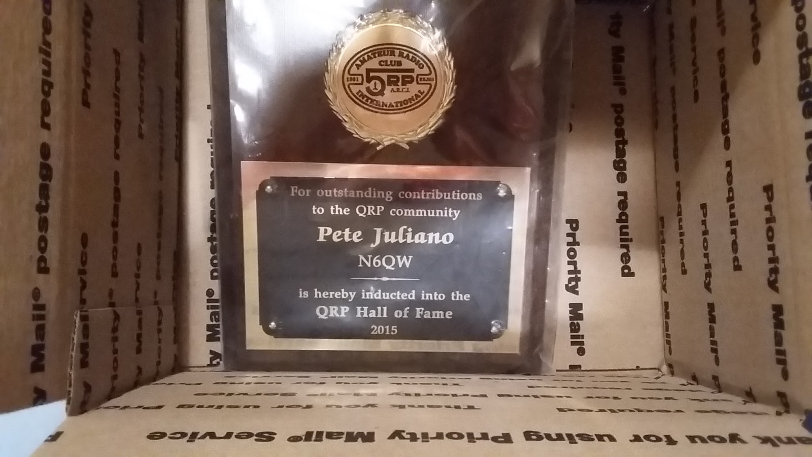
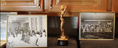
We’ve got a problem: Pete Juliano and the QRP Hall of Fame 🙁 PLEASE HELP!
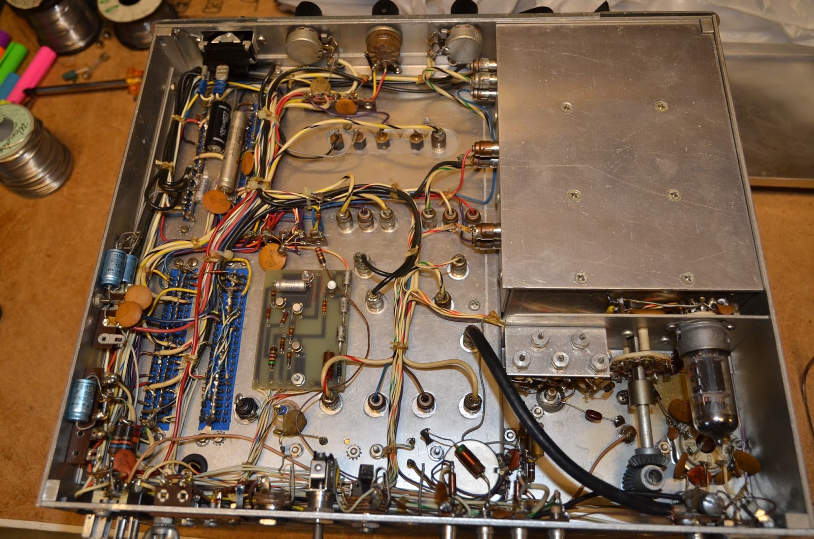
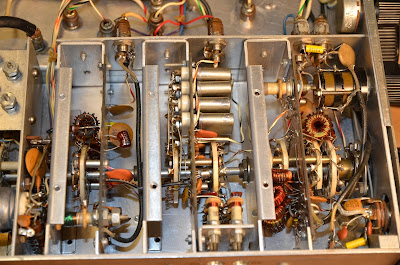
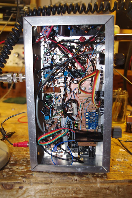
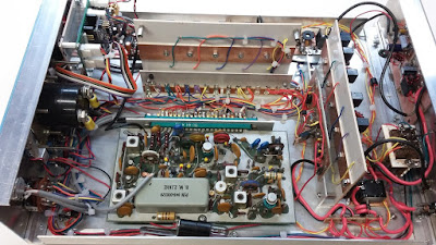
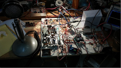

BENCH REPORTS
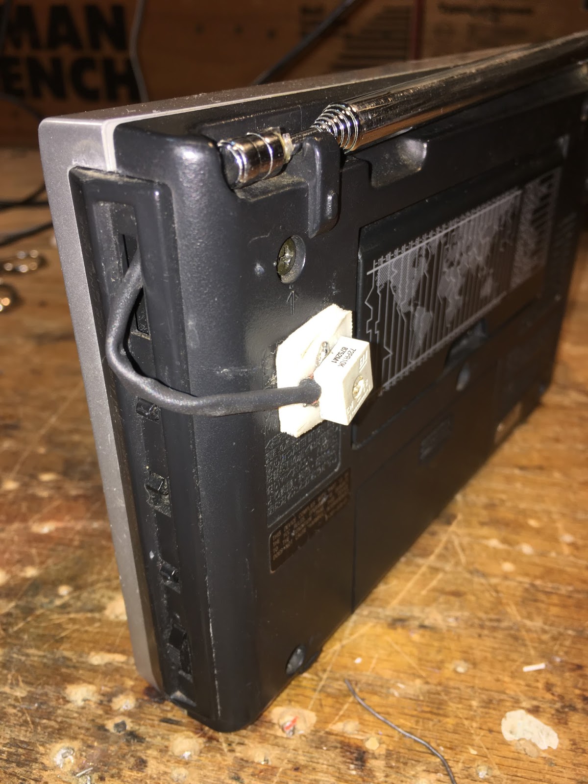
Pete Releases Smoke (wiring harness)
Pete’s DifX on 60
Architecture and Dual Conversion (uBITX: uses ALL THREE clocks on the Si5351)
The Big Kahuna
ON HACKADAY with Philco SB100 SEE! QRP!!!!!
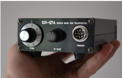
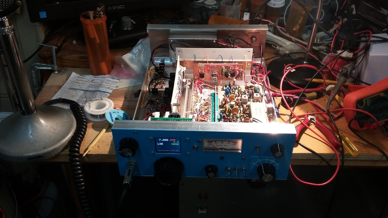
BITX60
Cap Stack Hack mod (with leads)
Let the smoke out of an Si5351 (shorted output) Several actually.
(Same day delivery zone for Amazon — but no drones or parachutes yet.)
Installed scanning switch
Observations on 60. All the weird bands have a 6 in them: 160, 60, 6
The good: 100 watt limit, wire antennas
The bad: Kind of cliquish– like 75, not much of a CQ band. Channels. Not much activity.
Met Josh KE8CPD on 40. BITX 40!
TRIBAL KNOWLEDGE:
Socketry: How to keep BNC jacks from spinning loose?
Do you heat shrink?
Feel Tech Sig Gen might not have blocking cap at the output.
Speaking of which, when I spoke of the Ne602, I mostly meant blocking caps, not bypass caps.
How come they don’t have a cable TV channel devoted to radios? They have HGTV? Why not HBTV?
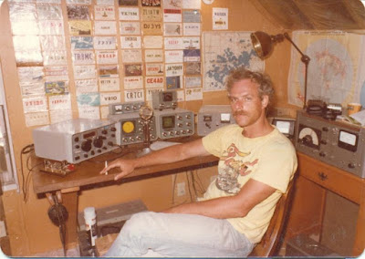
REPORT FROM WINTERFEST
Bad weather. Tailgaters wimped out!
Combined forces with Armand WA1UQO.
Met up with Charles AI4OT.
Acquisitions: 1/4 phono jacks, carbon mic, vero board, disc caps, weather radio,
LARGE collection of Electric Radios from Armand. Wow.
Electric Radio notes: 1st Fifty Years of Sideband 1991 articles by Jim Musgrove K5BZH
Why LSB on 75? — so AMers couldn’t follow to top of band
W2, W6, W8s liked phasing, W3, W4, W0 more into filter rigs.
Early SSB guys turning on carrier and talking AM hams into SSB RX.
Kelvinator Refrigerator rigs.
A reading on the homebrewing of SSB rigs.
Tony Fishpool on QSO Today! Pete mentioned prominently.
Good Hacks from ND6T on BITXHacks, Stockton Bridge
MAILBAG

LINK: http://soldersmoke.com/soldersmoke195.mp3

N7SUR’s Nice SSB Filter — Nail Polish Stuff Adds Soul to the New Machine

That’s a beautiful graph, don’t you think? In addition to the very pleasing results, I liked Bob’s methods: the “by hand” collection of the data points using an AD9850, a ‘scope and a notepad (see below); the filing down of ceramic disc caps; the use of nail polish hardener — all this adds a definite artisanal element to this project and puts more soul in the new machine.

Like Bob, I too kind of bailed out on the Q calculation when I was doing this. But as I recall there is a variation on the G3UUR method that yields this parameter too, right?

Bill:

I’m reluctant to share this with you because the results appear too
good. I’ve attached a graph showing my four crystal, 11Mhz
filter measurements. The graphed points are read values using my
AD9850 DDS VFO feeding to a TEK scope.

A TIA amp was used for input and output of the filter. My development software was the Steder-Hardcastle software as presented in November 2009, QEX.

I am now practiced in the black art of filing off the tops of disc
ceramic caps to “adjust” their values. This black art also involves
the mysterious qualities of Sally Hansen Nail Hardener.


Let me share my method for developing the filter.

I’ve built CW filters before but this was my first effort at SSB
bandwidth which is less forgiving.

The G3UUR oscillator method (see page 3.19 in EMRFD) is a simple and
effective filter design method. but it does not provide a measure for
crystal Q, a value which impacts filter insertion loss.

So I decided to choose crystals with proven pedigree. These were 11 Mhz crystals from Mouser, part number 20-HCA1100-S. A lot of ten costs $5. These were the crystals selected by Jim Kortge, K8IQY, for use in his 2N2/20 rig.

For software, I use the Dishal package that can be downloaded from the ARRL and other sources. This package was the basis for the
Steder-Hardcastle article in November 2009, QEX. The “Xtal” pull down
menu provides entries for an individual G3UUR oscillator.

Simply put, all critical filter input values are generated by reading
the change in crystal frequency as an additional capacitor is added
into the oscillator circuit.

I suggest starting with a 4 crystal filter. Only two capacitor values
were required for my filter. Five capacitors were required–two series
and three shunt.

Start by reading the “open switch” frequency for each crystal. Sort
the crystals into increasing frequency order and choose the four with
the most narrow frequency span.

Using the pull down menu measure the individual crystal measures for
Lm, Cm, and series frequency. Average these across the four crystals.

The Lm or Cm and series frequency are placed into the Dishal software
main menu. Also enter the average Cp which is the measured capacitance across the crystal leads.

Finish up the main menu entries by entering the number of crystals (4), and the desired bandwidth–generally 2.4 to 2.9 Khz. Finally enter the acceptable ripple, which is often 0.1db.

Let the software calculate the filter values. Expect some odd
capacitance values. By changing the filter bandwidth–say from 2.4 Khz to 2.35 Khz I can move one of the capacitance values to a standard value.

The software also displays the input and output impedance. If the
filter is centered between two TIA amps, this filter impedance must be
transformed to 50 ohms in the amps. This provides the transformer
winding ratios.

The Dishal software has always given me good results. But I haven’t
compared its results to Ladpac–especially GPLA.

Bob -N7SUR


Of Waterfalls, SDRs, and Homebrew Analog Rigs: Words of Wisdom from W8JI

W8JI


It happened again today. Conditions were good and I was BOOMING into the NYC area on 40 meters. 40 over. Everyone liked the signal and said it sounded great. Except for one anonymous grump who chimed in to say that I was “9 kc wide.” I imagine he was basing this on a quick look at his super-dooper SDR waterfall, without any consideration of signal strength or the characteristics of his own receiver. Sigh. The Waterfall Police had struck again.

OM W8JI gives a great description of the pitfalls of this kind of “you’re-too-wide-because-my waterfall-says-so” reasoning. Check it out. And keep it handy in preparation for your next encounter with the 40 meter Waterfall Police.

https://www.w8ji.com/checking_bandwidth_with_receiver.htm

Homebrew SSB in Germany: DK7IH

Pete WB9FLW alerted us to the work of Peter DK7IH, a very talented homebrewer who recently followed the lead of Pete N6QW in building some really small SSB transceivers. Here is his Micro QRP SSB rig:

You can see more of his fine work here:

https://radiotransmitter.wordpress.com/

https://www.qrz.com/db/DK7IH

Have you guys noticed how many Peters there are among homebrewers, especially among SSB homebrewers? Just from recent mentions on this blog:

Pete Juliano N6QW
Pete WB9FLW
Peter Parker VK3YE
Peter DL3PB
Peter W1UO
Peter GW4ZUA
Peter G6GNR
Peter VK2EMU
Peter VK2TPM
Peter HA5RXZ
Peter DL3JIN

SolderSmoke Podcast #192 FPM Rig, BITX Module Madness, HRO Al Fresco, Boatanchor Day, Mailbag


SolderSmoke Podcast #192 is available:

http://soldersmoke.com/soldersmoke192.mp3

N6QW COMPLETING AN ORBIT TOMORROW!!!! Happy Birthday Pete!
Shortwave Woes: Deception and Disappointment!
Voice of Vietnam! But it is from Cyprus Creek S.C.
Radio Athmeeya Yatra in Punjabi! but it is in Nauen Germany. Yuck!
Sort of like these 9 cents per minute on-line relay ham stations. Yuck I say!
You know you are a hardcore homebrewer when a near empty can of Deoxit makes you nervous, so you order more, just in case.
Bench Reports:
Pete:
FPM FPM FPM!!! Tell us about it!
BITX 40 Module in Juliano Blue
Explaining the BITX 40 to the local club.
CULTURE SHOCK! Plug and play vs. Hardcore Homebrew.
Bill:
An EXTROVERTED BITX 40 Module
QRO with 24 volts on the Drain: 20 watts out. Heatsink upgrade, Chris KB4PBJ Thanks.
Analog Readout — Dymo tape and a Sharpie arrow
REVERSE POLARITY PROTECTION Where the perfect is the enemy of the good enough.
HRO no longer AL FRESCO Boxed up. Thanks Armand. Thanks Tim Sutton. Still working on AM receiver. Not inhaling very well.
Boatanchor Day: Fixed HT37 and hurt my back. Really. Got 160 meter station going. Changed ball bearings on CW key.
Next project. Another BITX 40, but perhaps for 160, 75 and 60 with Si5351 and plug-in filters.
Sideband History: THE SIDEBAND SUZY AWARD. Pete deserves this. I say we revive it.
LEX: Al Fresco. And Tim Walford calls them “Blackbox rigs” not “rice boxes”
HB2HB contacts. Often with guys who built their linear. I say that counts Too!
MAILBAG


“Sideband Suzy” and the History of SSB

Farhan alerted us to a very interesting presentation on the history of single sideband: It was in episode 81 of Bob Heil’s “Ham Nation” show. It starts at minute 22:

https://www.youtube.com/watch?v=xSF0WBdK1IQ&feature=youtu.be

Two things really caught my attention:

— Note how OM Carson, way back in 1915, had figured out how to get rid of the carrier, but needed some way of eliminating the unnecessary sideband. He did it by using his antenna tuner as a filter. FB OM!

— In the early days of SSB, when it was an exciting new technology, hams had regular “sideband dinners.” At these events an award was presented. Kind of like an Oscar or an Emmy I guess. The award was the “Sideband Suzy” (see above). Kind of a classic figure… but half of Suzy was missing!

It’s Ugly, But It Gets You There: Pete’s Latest Rig

That, my friends is an extreme example of what we mean when we use the word “rig.” This magnificent machine sent Pete’s melodious voice across the mighty Pacific several times during the recent CQ WW contest.

Pete wrote to Jun:

Hi Jun,
This weekend is the CQ World Wide SSB contest and I just worked three JA stations on 40 Meters. The time 1400 UTC. I must confess that I was using 600 watts to my droopy dipole but they came back on the first call. So there are paths open and perhaps 600 watts was overkill but the timing seems like it works for a good path to the west coast. Along the way I also worked a station in Hawaii (KH6).
See if you can find some 813 tubes as they make a great grounded grid linear amplifier tube and a pair will give you 600 watts. see http://www.ohio.edu/people/postr/bapix/813amp.htm
The rig I was using is shown below. The mainboard came from a Hallicrafters FPM 300 (late 1960) to which I added the Rx Tx Mixer (SBL-1), my stock 2N3904 bi-directional amp board, the 2N2222 + BD139 driver stage using the EMRFD circuit and a 2SC2075 final which gives about 3 watts. This in turn drives an intermediate SS amp to 100 watts and then the SB200 to 600 watts. The FPM 300 used a 9.0 MHz IF frequency.
Of course no rig today from N6QW would be complete without a Si5351 and the color TFT display. Rounding this out is an LM386 audio amp stage. Cosmetically the rig doesn’t look pretty but sure works well.
73’s
Pete N6QW
(The comments about the 813s are kind of SHOCKING, coming from a member of the QRP Hall of Fame!)