It has been repeated so often and for so long that many of us have come to believe it. I myself believed it for a while. Like many myths, it has a ring of truth to it. And it is a simple, convenient explanation for a complex question:
Why do ham single sideband operators use LSB below 10 MHz, but USB above 10 MHz?
Here is the standard (but WRONG) answer:
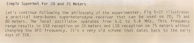
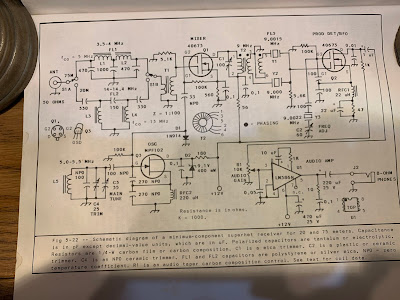
In the early days of SSB, hams discovered that with a 9 MHz SSB generator and a VFO running around 5.2 MHz, they could easily reach both 75 meters and 20 meters (True). And because of sideband inversion, a 9 MHz LSB signal would emerge from the mixer as an LSB signal (True), while the 20 meter signal would emerge — because of sideband inversion — as a USB signal (FALSE!) That sideband inversion for the 20 meter signal explains, they claim, the LSB/USB convention we use to this day.
Why this explanation is wrong:
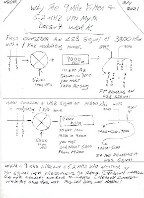
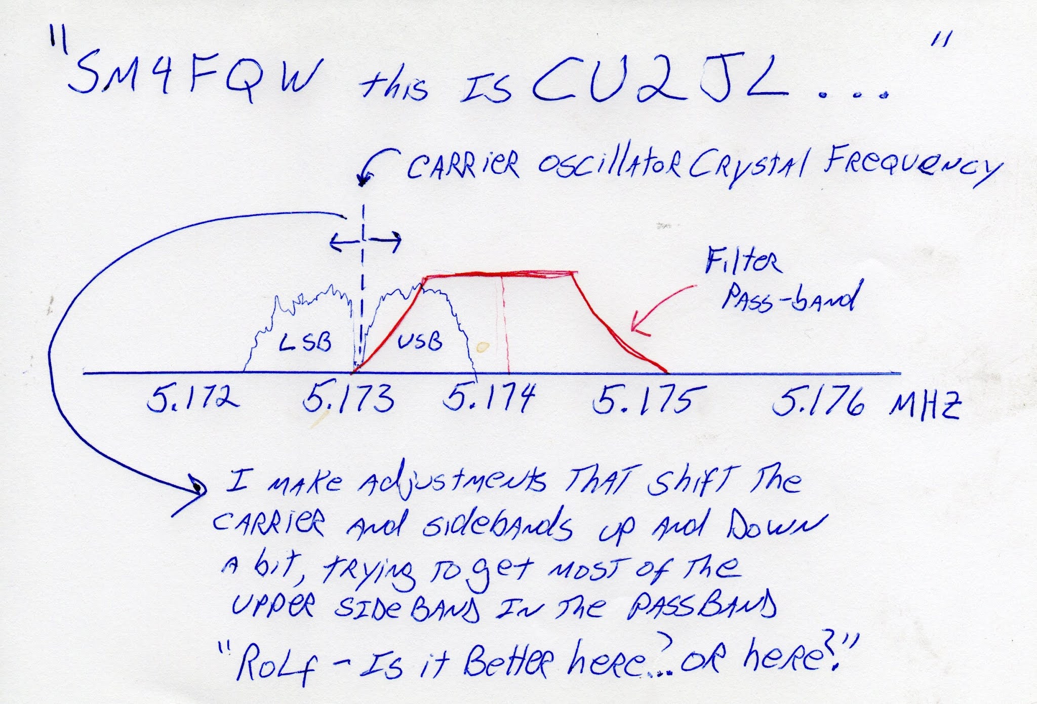
There is a very simple rule to determine if sideband inversion is taking place: If you are subtracting the signal with the modulation FROM the signal without the modulation (the LO or VFO) you will have sideband inversion. If not, you will NOT have sideband inversion.
So, you just have to ask yourself: For either 20 or 75 are we SUBTRACTNG the Modulated signal (9 MHz) from the unmodulated signal (5.2 MHz)?
For 75 meters we have: 9 MHz – 5.2 MHz = 3.8 MHz NO. We are not subtracting the modulated signal from the unmodulated signal. There will NOT be sideband inversion.
For 20 meters we have 9 MHz + 5.2 MHz = 14.2 MHz. NO. No subtraction here. No sideband inversion.
So it is just arithmetically impossible for there to be the kind of happy, easy, and convenient USB/LSB situation described so persistently by the myth.
———————————
We discussed this several times on the podcast and in the blog:
https://soldersmoke.blogspot.com/2015/05/sideband-inversion.html
https://soldersmoke.blogspot.com/2012/05/usblsb-urban-legend-debunked.html
This myth shows up all over the place:
We see the myth here:
http://n4trb.com/AmateurRadio/Why%20The%20Sideband%20Convention%20-%20formatted.pdf
Here the web site owner warns that this is “highly controversial.” Really? Arithmetic?
http://9m2ar.com/lsb7.htm
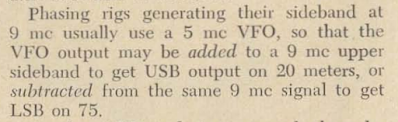
The myth is very old. Here is a clip from a 1966 issue of “73” magazine:
https://worldradiohistory.com/Archive-DX/73-magazine/73-magazine-1966/73-magazine-01-january-1966.pdf
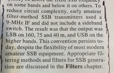
Finally, to my disappointment, I found the myth being circulated by the ARRL, in the 2002 ARRL Handbook page 12.3:
The fact that the Handbook attributed this to a desire to “reduce circuit complexity” by not including a sideband switch should have set off alarms. We are talking about hams who built their own SSB rigs, usually phasing rigs. A sideband switch would not have added significant circuit complexity. I think they could have handled it.
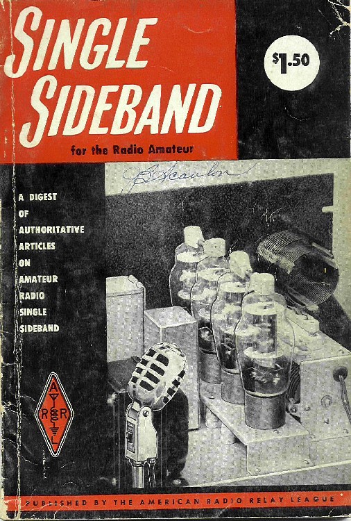
It is interesting that earlier ARRL Handbooks do not repeat this myth. I found no sign of it in Handbooks from 1947, 1959, 1963, 1973, and 1980. And I found no sign of it in several editions of that great ARRL book “Single Sideband for the Radio Amateur.”
For my next homebrew rig, I will build a rig that DOES do what the myth promises. I will have the SSB generator running on 5.2 MHz USB. The VFO (out of an old FT-101) will be running around 9 MHz. So for 75 meters we WILL be subtracting the signal with the modulation from the signal without the modulation: 9 MHz – 5.2 MHz = 3.8 MHz. There will be inversion. This 75 meter signal will be LSB. For 20 we will just add the 5.2 MHz USB signal to the 9 MHz VFO. There will be no inversion. We will have a USB signal on 20. I’m thinking of calling this new rig “The Legend.” Or perhaps, “The Mythbuster.”