When this ad appeared in 73 Magazine in February 1963 I was 4 years old, living on Manhattan Island. Pete N6QW was in the Navy, heading to Midway Island.
Pete writes:
——————-
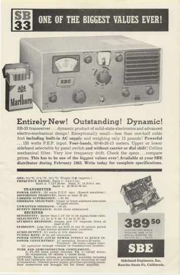
This ad has a tremendous impact on the foundations of our hobby. The SBE-33 was pure genius in its design and implementation.
It is a hybrid rig using Germanium transistors –the transistor was only 15 years old
The Mechanical band switching showed the strong use of mechanical assemblies
The small size was simply amazing
The Bi-lateral circuitry predates any Bitx circuits.
The urban legend was that a team of illuminati were involved in its design (Don Stoner is one name that pops up)
The Japanese were a quick study and the FTdx100 in 1967 is a result, only better.
Many are still around in shacks. I have three
Gonset was well known for innovative designs – the Gooney Box is another example. Look at all of his compact mobile equipment.
The next point – the final owner of SBE was Raytheon thusly the next generation of SDR Radio Equipment for the US Air Force can trace its pedigree to the SBE-33.
This was the appliance box of 1963. I saw my 1st SBE-33 (August 1963) when likely you were in the 2nd Grade and I was headed off to Midway island.
———————–
I have an SBE-33 that N6QW sent me. Thanks again Pete!
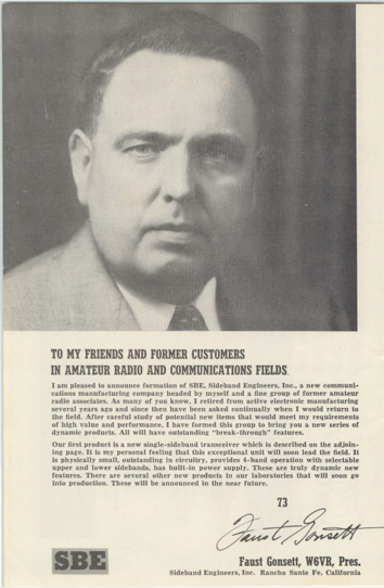
Also, I’d like to note that W6VR had a very cool name. Faust Gonsett. I just sounds like the name of a real radio guy. Google says this of the given name Faust:
“Faust as a boy’s name is of Latin origin, and the meaning of Faust is ‘fortunate, enjoying good luck.’ Indeed.
November 4, 2013 Special hour-long interview with Peter Parker, VK3YE — Early experiences with radio — CW — DSB Gear — Simple gear, and gear that is TOO simple — VXOs, Super VXOs and Ceramic Resonators — Building receivers — Chips vs. Discrete — Making the leap to SSB — The Knob-less wonder and the BITX — No need for a sophisticated workshop — Advice for new phone QRPers
It has been a while since we last did a bandsweep. Too long. Here is one using my recently fixed up Hammarlund HQ-100. Repair details are in recent videos.
For this bandsweep we cover most of the HF band and even briefly dip down into the AM broadcast band:
Demonstration of the Hammarlund HQ-100: Radio Marti, 40 meter AM, 40 Meter SSB, 40 meter FT-8, 40 meter CW with and without the Q multiplier, classical music on WRMI, WFAX 1220 kHz AM, WWV 20 MHz, CB!, 17 meter SSB, the 20 meter BS position, the effect of AVC and the Noise Limiter, SSB with the internal BFO and with the Q multiplier as BFO. CW with the internal BFO AND the Q multiplier.
I’ve recently finished most of the circuitry on the 17-12 meter dual band SSB transceiver. I have had contacts with it on 17 meters, but until yesterday morning (March 22, 2022) I had not had any contacts on 12 meters. This morning I talked to Paul EA5JZ in Valencia, Spain. I was running the 17-12 rig barefoot at about 5 watts with the final being one RD06HHT FET. The antenna was my 75 meter doublet fed with window line — I had to modify the tuner to get it to work on 24.9 MHz. It was very cool to have my first 12 meter contact be QRP, HB and with Spain.
There is a LOT of soul in this new rig. Here is a partial list of contributors:
— Overall BITX design: Farhan VU2ESE
— Termination Insensitive Amplifiers (TIA): Wes Hayward W7ZOI and Bob Kopski K3NHI.
— TIA boards from Todd K7TFC
— ASK-1 Mixer from Armand WA1UQO
— VFO design parameters from Joe Carr K4IPV (SK)
— VFO stability ideas from Frank Harris K0IYE and Mike Murphy WU2D.
— HT-37 Tuning Capacitor bought from e-bay at suggestion of Pete Juliano N6QW.
— Pine board base of the rig: Frank Jones (SK) W6AJF’s preferred building technique.
— DTC Band-Pass filter circuits from Han Summers G0UPL.
— Low pass filter values from G-QRP web site.
— Idea of using RD06HHT instead of IRF-510 in the final: Pete Juliano
— Heat sink from Chris KD4PBJ
— Trifilar Toroids used in many places from Farhan VU2ESE.
Here is an update on the 1712 transceiver project. The receiver circuitry is done and I can listen on 17 and 12 meters. In this video I was using my 75 meter doublet tuned to 17 meters (reception on 12 was pretty good using this antenna). As you can see, I found a temporary solution to the VFO dial problem — I am using the cardboard tube from a coat hanger super glued to a knob. The tube fits snuggly over the shaft from the VFO assembly.
With just two TIA amps (one on either side of the 10 pole filter) and the AF amplifiers, I now have it inhaling on 17 meters. But nothing heard so-far on 12. On both bands I can hear the band noise, but just barely. So I may try some RF amplification ahead of the mixer. What do you guys think about this? I think the two TIAs and the crystal filter are providing 30 db of gain.
I want to get the receiver circuitry working well on both bands before I build the T/R and transmit amplifier circuitry.
It is nice to have a project on the bench!
I am trying to find a shaft extender or adapter for that big beautiful HT-37 main tuning cap. The shaft on the capacitor has a width of 1 cm or 0.393701 inches. I need something that will grab onto that and allow for the connection of a tuning knob. Please search your junk boxes!
Dennis WC8C is the event coordinator for the radio club in Michigan that I recently spoke with. He mentioned to me that he was working on a homebrew 6 meter rig. FB Dennis. I see lots of tribal wisdom in your approach, especially in your decision to do this in a stage-by-stage modular form.
Dennis’s rig is obviously a work in progress, so if anyone out there has any helpful hints (especially on the carrier suppression and on the testing for spurs and splatter) please share them with him via e-mail or blog post.
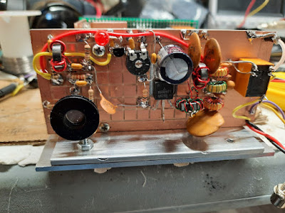
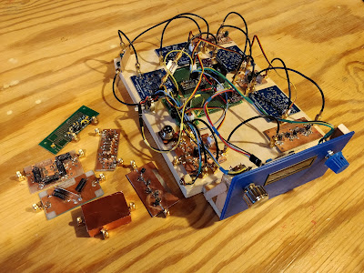
This is my 6 Meter homebrew transceiver, currently work in progress.It is a single conversion super –heterodyne design.I constructed each stage independently with SMA connectors.This is so I can re-make sections as needed, and will allow me in the future to swap sections to experiment with alternate designs.The VFO and BFO are controlled using a SI5351 with an Arduino micro controller.I currently have separate SI5351 modules for VFO and BFO because I suspected issues with cross-talk.These issues may not actually be real, so once I am happy with the performance, I will test again with just one module to see if it is OK.The Power Amp is still on the to-do list, so output is well under 0 DBm
The Blue boards were designed by me and ordered on-line.The other boards I etched myself.Construction is mostly surface mount because I find it easier than drilling all the holes.SMD components are mostly 805 and 1206 size. Transistors are SOT23.
The Band Pass filter is a 5 coil design made with air-core inductors.
3 bi-directional termination insensitive (TIA) amps are used (blue boards).Total RX gain is about 44db.Total TX gain is about 16db.Each board has its own independent RX/TX switching circuitry (mosfet based) and is fed with +12.5, GND, and RX/TX logic signal from the Arduino (3V logic and up will work)
The Mixer and modulator are both Diode Ring mixers.
The 12 MHz SSB filter is a crystal ladder filter similar to the one used in the uBitx.
The Mic and audio pre-amp (also a blue board) is made on a modified TIA amp board.I had 10 of these boards made, and the needed circuitry was largely the same, so I modified the board with a rotary tool and jumpers.
The Audio amp is a PAM8403 module and drives a headset.I did make some modifications to the module so it runs in-spec and to eliminate the power on audio pop.
The challenges I have been having are mostly related to spurs, splatter, carrier suppression and TX audio quality.I have been gradually tweaking these things to improve operation before I start on a power amp.My IF is 12 MHZ, and I was using the LSB side of the crystal filter because it is sharper (VFO 62 – 66 MHz) but have recently changed over to the USB side of the filter (VFO 38 – 42 MHz).This eliminated the spurs I was seeing near the pass band.I still need to make some adjustments to the crystal filter as it is too broad.
I still have some splatter and audio quality seems low, but I am starting to doubt my test setup.I see the splatter on the RTL SDR, but I don’t see it on the Tiny SA.The spatter happens at ~160 KHz intervals.I am hoping to find someone local with a better spectrum analyzer to help me verify if it is the rig or my SDR dongle/test setup.
The modules to the side of the picture are my rejects/experiments.The one covered in copper shows how I eventually will shield all the modules.I 3D printed a cover for the board, when wrapped it with copper tape, soldered to the bottom ground plane.The one shown is a diode ring modulator.For some unknown reason the carrier suppression is rather poor.I had previously made a junk-box modulator that had much better carrier suppression.I don’t know why it is better than the one I more carefully made for the radio, but until I figure it out, I am using the junk box version.The junk box modulator uses unmatched schottkey diodes, whereas the “final” one uses a 4 diode SMD package because I wanted them matched – I thought this would be better, but maybe not.
I was impressed by those bandpass filters. I will try to do something similarly robust on my 17/12 rig.
Paul’s miniaturization of this rig is really astonishing. I would go nuts trying to keep it this small. I just couldn’t do it.
Look closely at the boards he uses. They look like printed circuit boards, but with all the components and all the soldering on one side. This is very smart — this makes it easier to troubleshoot and to change components.
I was glad to see at least one NE-602 in there. FB.
The video is above. Check out Paul’s blog for more info:
6 weeks in the DR for Bill One contact on uBITX. More SW listening. Repaired my Chrome Book in Santo Domingo! Christmas Present for All: James Web Space Telescope launch
I spent most of January in the tropics, away from my workbench. This seems to have had a good effect on my 17 meter split TX/RX project. As I was leaving, heading south, I was thinking about several difficult options to deal with my spur problem (see previous blog posts). I thought about turning the transmitter into a transceiver by building a receiver board. I thought about putting San Jian frequency counters on both the transmitter and the receiver, then doing a visual numerical “netting” by just putting the two devices on the same frequency (I actually ordered 3 San Jian counters). The counter option was even more complicated than it at first seemed — I would have to build a converter to shift the RX VFO frequency up. VK2EMU suggested a tube type “Magic Eye” (interesting idea, but also complicated). This was getting out of hand.
When I got back home, I took a new look at the problem. I decided to take one more shot at suppressing the 8th harmonic of the carrier oscillator. I had already built a new oscillator and buffer using the circuit from Farhan’s BITX20. And I had put it in a metal box. Now I decided to do three things:
1) Tighten up the low pass filter at the output of the buffer by moving the cutoff frequency lower (to around 7 MHz) thereby getting a bit more suppression at 41 MHz
2) Try putting a series LC shunt circuit tuned to 41 MHz at the output of the carrier oscillator (between the oscillator and the buffer).
3) Reduce the voltage to the oscillator/buffer. I have this on a pot, so I can adjust it down to the point where the remnant of the harmonic is no longer audible, while keeping the main carrier osc signal sufficiently strong.
It seemed to work. I could now hear the desired frequency for spotting, without the confusing tone from the spur.
Why had I been able to do this back in 2002 in the Azores using a simple trimmer cap to ground? My guess is that I was using my Drake 2-B as the receiver. The trimmer cap to ground may have reduced harmonic output. And I was probably cranking back the RF gain on the 2-B to the point where I could hear the desired signal but not the remnants of the spur. I have no RF gain control on the Barebones Barbados receiver that I am using in this project.
So, what’s the lesson from all this? Well, if you are faced with a serious technical problem, and you find yourself considering complicated and difficult solutions, go to the Dominican Republic for about a month (especially if it is January or February), and then take another look at the problem when you return. If you are unable to travel this far or for this long, taking a walk or taking a weekend break from a troublesome problem will likely have a similar mind-clearing effect.
The video above shows part of a February 1, 2022 QSO with Gar WA5FWC using the split TX/RX 17 meter rig. Gar is an amazing long-time SSB homebrewer who got his start with phasing rigs back in the day.
I first came across the above picture of K0IYE’s inspirational, completely homebrew station many years ago in the pages of “World Radio” magazine. I have already linked to Frank’s book many times over the years, but it is so good that I regularly feel compelled to write about it again. Frank updates the book. Just check out the introduction to his website. Frank even has a Spanish language version of his book. All for free. Thank you Frank.
The introduction to Frank’s web site:
Over the last century amateur radio has evolved into numerous different
hobbies. Some hams enjoy weekend contests in which they try to
contact as many stations as possible. Others talk to as many of the
world’s 341 call areas as possible and collect QSL cards to prove it. Other
hams just like to ragchew with friends. Still others communicate over
long distances at UHF frequencies using satellites, meteorites, aurora and
other substitutes for a sunspot-charged ionosphere. Some hams provide
communications for their communities during emergencies.
Many of us have returned to the early days of radio by building our own
equipment from scratch. Most home builders start by building QRP (low
power) transmitters. If this doesn’t satisfy your urge to build something,
you can move on to build the entire station. That is what this website is about.
As often happens, I may have jumped the gun in declaring the exorcism of my 17 meter transmitter to be a success. As readers of this blog will recall, my problem was that when trying to “net” my separate 17 MHz receiver and transmitter, at around 18.116 MHz I could hear more than one tone as I tried to get to zero beat. The 8th harmonic of my 5.176 MHz carrier oscillator was mixing with the 23 MHz VXO signal and producing a spur. I could probably knock the level of this spur down below FCC limits, but — and here is the problem — I probably could never knock it down to the point that it would not be audible in the sensitive receiver that sits right next to the transmitter. So this is really a netting problem, not really a spur problem.
I don’t want to try another filter frequency — I have VXO crystals that really work only with a filter at 5.176 MHz.
So here is my current idea: Build a receiver board and turn this thing into a transceiver. Switch with relays the input and output of the 5.176 MHz filter, and use relays to switch to the receiver board the VXO and carrier oscillator signals.
Making this thing a transceiver would eliminate the need for netting. This should solve my problem.
First, thanks to all who sent in suggestions. They came in literally from around the world, and this is a demonstration of the IBEW in action. I used or at least tried all of them. They were all good ideas.
Following Vasily Ivananeko’s pseudonymous suggestion I rebuilt the carrier oscillator (apologies to G3YCC). I used the carrier oscillator/buffer circuit from Farhan’s BITX20.
Henk PA0EME said I should look at the signal level at the input ports of the NE602 mixer. Henk was right — the VXO input was far too high. I lowered it, but the problem persisted.
At first, I thought that the spur in question was so small that it would not show up on the air. I could not see it in the TX output using my TinySA spectrum analyzer. That was good news and bad news: Good that it was not showing up on the air, bad that I could not see it in the TinySA and use that image in the exorcism.
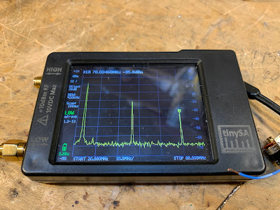
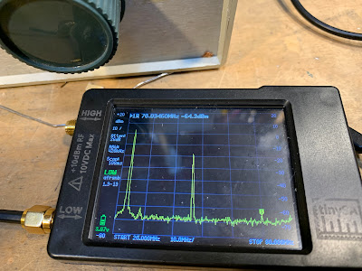
At first I thought that the spur was being caused by the 10th harmonic of the carrier oscillator and the third harmonic of the VXO. This seemed to fit. So, following VK3YE’s sage advice, I built a little 69 MHz series LC trap (using a coil sent by AA1TJ, on a board CNC’d by Pete N6QW). That trap succeeded spectacularly in crushing the 10 harmonic. Look at these before and after shots on the TinySA:
Before Trap
After Trap
Spectacular right? But guess what? The problem was still there.
I scrutinized the situation once more. I realized that the spur would be more visible if I put the TinySA on the input of the transmitter’s PA (a JBOT amp designed by Farhan) as opposed to putting it on the output. Watching the spur and the needed signal move in the TinySA as I tuned the VXO, I realized that they were moving in opposite directions. This indicated that the spur was the result of a carrier oscillator harmonic MINUS a VXO-generated frequency (as the VXO frequency increased, the spur frequency decreased). Looking at my EXCEL spread sheet, I could see it: 8th harmonic of the carrier oscillator MINUS the main output of the VXO.
To confirm this, I plugged the values into W7ZOI’s Spurtune program. Yes, the spur popped up and moved as predicted.
For further confirmation I shut down the carrier oscillator by pulling the crystal from the socket, and then just clipped in a 5.176 MHz signal from my HP-8640B signal generator (thanks KB3SII and W2DAB). Boom! On the TinySA, the spur disappeared. Now I at least knew what the problem was: a harmonic from the carrier oscillator.
Following good troubleshooting practice, I turned off the gear and went to bed. When I woke up, an idea came to me: Before launching into a lot of filtering and shielding, just try running the carrier oscillator at a lower voltage, seeing if doing so might reduce the harmonic output. I disconnected the carrier oscillator board from the main supply and clipped in a variable voltage bench supply. Watching the signal on my TinySA, I watched as the spur completely disappeared as I reduced the voltage from around 13V to 10V (see video above). The main signal frequency level did not change much. I tested this by listening for the hated extra tones. They were gone. Exorcised.
Key lessons:
— Spur problems are difficult to troubleshoot. Armstrong’s superhet architecture is, of course, great, but this is definitely one of the pitfalls. Single conversion makes life easier. IF selection is very important. Choose wisely!
— When looking at the TinySA as you tune the rig, pay attention to which way the spur is moving. This provides an important clue regarding the combination of harmonic you are dealing with.
— The TinySA is a very useful tool. It seems like it is easier to use than the NanoVNA (which is also a fantastic tool).
— It can be fun and rewarding to re-visit old projects. In the years between original construction and the re-look, new test gear has become available, and the skill and experience of the builder has improved. So problems that once seemed insurmountable become fix-able.
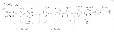
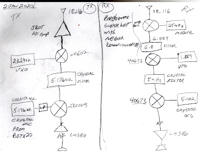
— Thinking through a problem and thinking about possible solutions is very important. It pays to step away from the bench to think and rest. Rome wasn’t built in a day. Here’s a rough block diagram that I drew up (noodled!) while trying to figure out this problem:
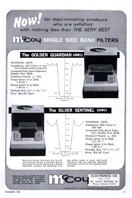
Last month we were talking about this company. Someone thought it was run by Lew McCoy of ARRL Homebrew fame, but it now appears that our Lew McCoy was not involved in the company.
Note how they provide TWO carrier oscillator/BFO crystals for each 9 MHz filter, one for USB, the other for LSB.
They were pricey too: In 2021 dollars, that Golden Guardian would cost $390.
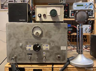
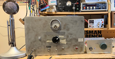
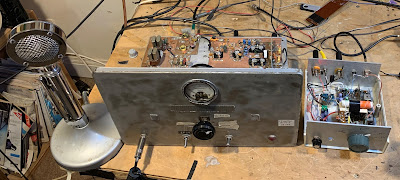
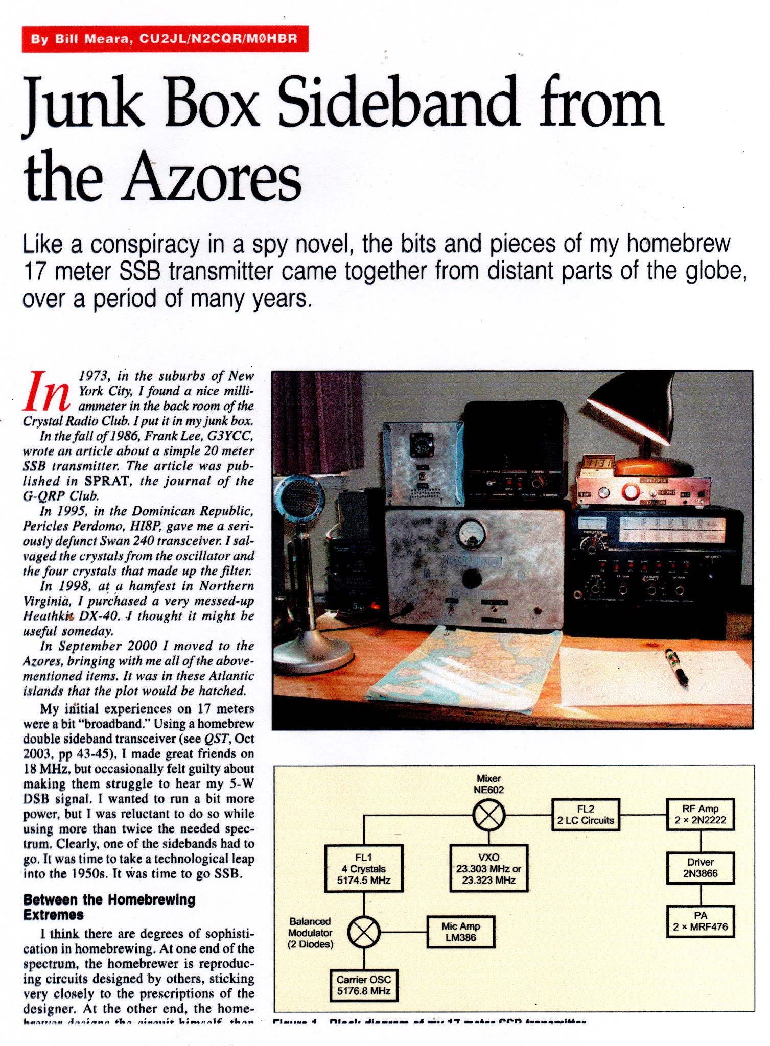
I built the transmitter almost 20 years ago. It is in the larger box, which originally housed a Heathkit DX-40. There is a lot of soul in that old machine. Details on this construction project are here: https://soldersmoke.blogspot.com/2021/12/junk-box-sideband-from-azores-2004-qst.html(The smaller box is a Barebones Superhet receiver set up for 17 meters.)
In the 2004 QST article I discuss a problem I had with “spotting” or “netting.” This is something of a lost art, something that you had to do back in the pre-transceiver days, when running a separate transmitter and receiver. This was how you got the transmitter on the receiver’s frequency. Essentially you would turn on the carrier oscillator and the VFO and let a little signal get out, enough to allow you to tune the VFO until you heard zero beat on the receiver. My problem was that around one particular frequency, I would hear several zero-beats. This made netting the receiver and the transmitter hard to do.
Important note: This is really just a problem with the “netting” or “spotting” procedure — the problematic spur does not show up in any significant way in the output of the transmitter. I can’t see it on my TinySA. But it is strong enough to be heard in the unmuted receiver sitting right next to the transmitter. And that creates the netting problem.
In the QST article, I said that I noticed that the problem seemed to be centered around 18.116 MHz. As I approached this frequency, the tones — desired and unwanted — seemed to converge. That was an important clue. In the article I said I thought that I could eliminate the problem with just one trimmer cap to ground in the carrier oscillator, but looking back I don’t think that this really fixed the problem.
I recently took a fresh look at it. Exactly which frequencies were causing the unwanted signals that appeared in my receiver?
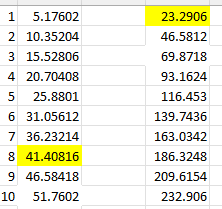
I used an Excel Spread sheet to find the culprits.
The first column shows the carrier oscillator and its harmonics. The second column shows the VFO when tuned for a signal at 18.11668 MHz (23.2927-5.17602), along with its harmonics. Check out the 10th harmonic of the carrier oscillator and the third harmonic of the VFO: 69.8781-51.7602 = 18.1179. Those two harmonics would produce the problem I had been experiencing.
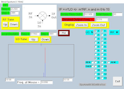
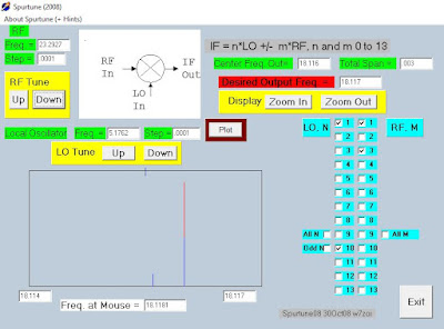
I turned to one of Wes Hayward’s programs for confirmation. Spurtune08 came in the EMRFD software package. Here is what I saw when I plugged in the above frequencies:
You can see the little spur off to the left of the main signal. In the program, as I tune the 23 MHz VFO frequency, the spur moves closer to the main frequency as I approach 18.116 MHz, just as it does in the real rig. Note that I have only turned on the 10th harmonic of the carrier oscillator and the 3rd harmonic of the VFO. Spurtune08 is very useful. Thanks Wes!
So, what is to be done? For now, I am just restricting my operations on 17 meters to above 18.120 MHz. (I worked several DX stations with it on December 27.) But obviously I need to fix this. This rig needs an exorcism. I think I only need to get rid of one of the harmonics, and the 10th harmonic of the carrier oscillator seems easier to kill. I’m thinking of putting the carrier oscillator in an Altoids box, and then adding some filters to knock down the 10th harmonic.
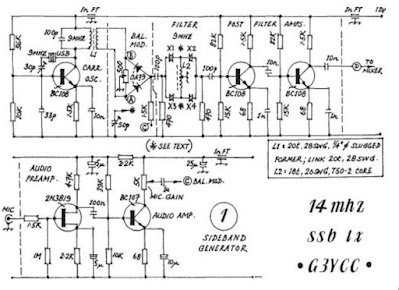
Here is the G3YCC schematic that inspired this rig. I used G3YCC’s carrier oscillator and balanced modulator circuits, just using a 5.176 MHz crystal and changing the tank circuit in the collector:
How would you folks knock down that 10th harmonic?
More on this project in due course. Lots of soul in this machine.
I’d forgotten about this article — thanks to Pete Eaton for reminding me. Click on the images for a better look at the article. For an even clearer view, download the images and then open them on your computer.
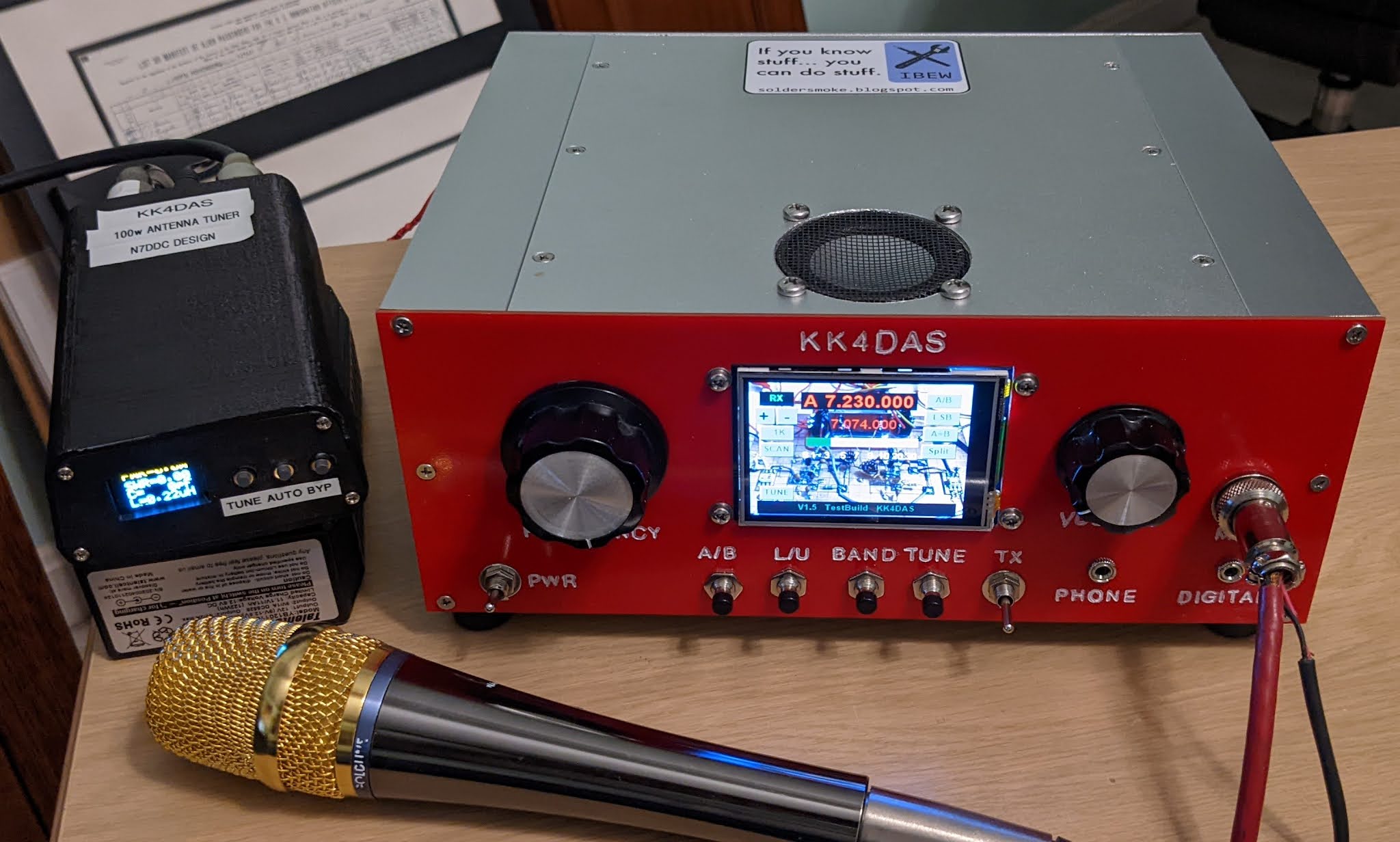
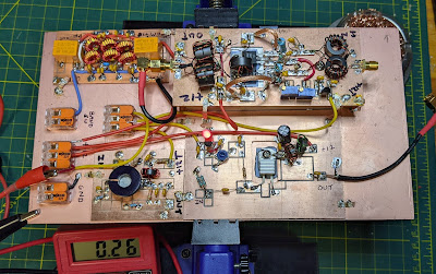
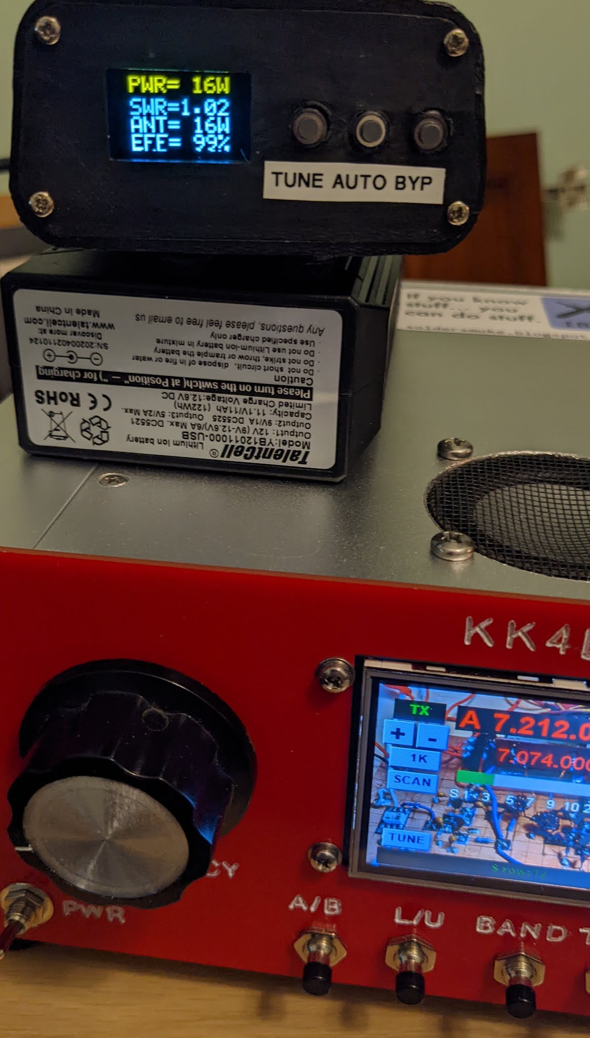
It is especially appropriate for us to use that Irish phrase because the design of the rig’s new final amplifier is out of Ireland. Our friend Dean KK4DAS added a 16 watt RF amplifier based on a design by EI9GQ to his homebrew N6QW Simple SSB rig. Note the IBEW label on the top.
Here is Dean’s blog post on this wonderful project (with video and more pictures).