Fabio’s Direct Conversion Receiver

Fabio, IK0IXI, is an electronic wizard from Civitavecchia, near Rome. Check out his very nice DC receiver. Note that wonderful direct conversion sound. Very cool that has it atop our beloved SPRAT. Below you can hear the effectiveness of the audio filter. Bravo Fabio!

Our book: “SolderSmoke — Global Adventures in Wireless Electronics” http://soldersmoke.com/book.htm Our coffee mugs, T-Shirts, bumper stickers: http://www.cafepress.com/SolderSmoke Our Book Store: http://astore.amazon.com/contracross-20

SolderSmoke on Tinkernation

SolderSmoke is on the Tinkernation web site:
http://www.tinkernation.com/your-story/bill-meara-homemade-radios-and-magic-carpets/#more-698
(Note that SPRAT is in both pictures.)

Our book: “SolderSmoke — Global Adventures in Wireless Electronics” http://soldersmoke.com/book.htm Our coffee mugs, T-Shirts, bumper stickers: http://www.cafepress.com/SolderSmoke Our Book Store: http://astore.amazon.com/contracross-20

SolderSmoke Podcast #145

SolderSmoke Podcast #145 (July 29, 2012) is available


http://soldersmoke.com/soldersmoke145.mp3

— Derecho Storm hits Northern Virginia

— Cappuccio impersonates a Pitt Bull
— July 4 Fireworks
— A 17 Meter QSO with W5JAY (QRP Hall of Famer)
— Rules of Thumb for Decoupling Caps (.1 uF now suspect)
— Heathkit: Mic jack? Or Mike jack? (Who is this Mike guy?)
— On the air with the K2ZA DX-100
— Saturnian Sidewalk Astronomy
— NJQRP “Chat With The Designers” — Mandatory Listening!
— Back with the ARRL: Goodwill Transmitters and Herring Aid Receivers
— Billy’s computer build and Arduino adventures
— Fixing up NE602 20 meter DC rig
— Join G-QRP! Support our SPRAT!
— MAILBAG

Our book: “SolderSmoke — Global Adventures in Wireless Electronics”http://soldersmoke.com/book.htmOur coffee mugs, T-Shirts, bumper stickers: http://www.cafepress.com/SolderSmokeOur Book Store: http://astore.amazon.com/contracross-20

The ZL2BMI DSB Transceiver

Oh man, I’ve been a fan of this rig for many years. I first read about it in the pages of SPRAT. Today I stumbled across what appears to be an on-line version of the instruction booklet prepared by Eric Sears, ZL2BMI. Lots of lore in there. Lots of soul in this rig.

This site has three documents describing the rig. All three are a lot of fun: http://www.mightymessage.com/

Three cheers for Eric Sears! Hip-hip…

Our book: “SolderSmoke — Global Adventures in Wireless Electronics”http://soldersmoke.com/book.htmOur coffee mugs, T-Shirts, bumper stickers: http://www.cafepress.com/SolderSmokeOur Book Store: http://astore.amazon.com/contracross-20

JBOT Installed in Azores 17 Meter SSB Rig

Even though one of their Coronal Mass Ejections is due to hit us soon, the radio gods have been quite kind to me this morning. I installed the JBOT amplifier board in the 17 meter SSB transmitter that I had built out in the Azores during the last solar cycle. The board went in without any trouble. And I was a very surprised when it DIDN’T break into oscillation and instability! Holy Cow! This one was stable from the start! Even when connected to my antenna! Eureka!

The rig still needs some peaking and tweaking. I’m only getting about 2-3 watts out and I should be getting 4-5. I did a quick and dirty “by ear” alignment — I just listened to my own signal with my trusty Drake 2-B and moved the carrier oscillator freq around a bit until the SSB audio sounded good (you never have to do that with DSB!).

For those of you not familiar with this rig, here is some background:
— Built on the chassis of an old Heath DX-40
— Crystal filter at 5.174 MHz. Filter rocks and carrier oscillator rocks from an old Swan 240 I picked up in the Dominican Republic from Pericles Perdomo HI8P (SK).
— Based on a design published in SPRAT by Frank Lee, G3YCC (SK).
–Heterodyne oscillator is a G3RJV Universal VXO circuit running at around 23.3 MHz.
— That orange cord to the big meter that you are no doubt wondering about is just a little circuit that monitors total current drawn by the rig. It bounces up and down as I talk. I put it in there mostly because I wanted to make use of a beautiful old Simpson meter that I picked up in 1973 at the Crystal Radio Club (W2DMC) in Valley Cottage, New York.

Going around, clockwise from below the meter: G3RJV VXO, carrier oscillator and two diode balanced modulator board, crystal filter (with NE602 mixer and post-filter bandpass filter to the left), JBOT PA. Audio amp (using op amp) below the chassis. T/R relay in the center (antenna changeover relay below the chassis).

Our book: “SolderSmoke — Global Adventures in Wireless Electronics”http://soldersmoke.com/book.htmOur coffee mugs, T-Shirts, bumper stickers: http://www.cafepress.com/SolderSmokeOur Book Store: http://astore.amazon.com/contracross-20

SolderSmoke Podcast #140

Universal VXO


A new episode of the SolderSmoke podcast is now available:

http://soldersmoke.com/soldersmoke140.mp3

January 9, 2012

— Santa Claus: Ice Skates, Brownie Box Cameras, and Piper Cubs
— On the air with 17 Meter Azores DSB rig
— Seeking balance (with antennas)

— 23/24 recycling of Azores SSB Rig: Adding Soul to the Old Machine!
— Attacked by my own soldering iron!

— RG-174, swarf, and other insidious threats to the homebrewer
— Inspiration from QRP Quarterly
— G3RJV validates the D-104
— T/R admonition from the 1973 Handbook (words to live by)
— The Woz on electronics and teenage social isolation
— BANDSWEEP: Straight Key Night at WA6ARA
— MAILBAG
Our book: “SolderSmoke — Global Adventures in Wireless Electronics”http://soldersmoke.com/book.htmOur coffee mugs, T-Shirts, bumper stickers: http://www.cafepress.com/SolderSmokeOur Book Store: http://astore.amazon.com/contracross-20

A Good Day in the Shack — 2B Fixed, SPRAT Arrives

The temperature has dropped to around 10 C today. Fall is in the air. So it was appropriate for me to do some work on an old tube radio. (Several of our correspondents have reported similar seasonal urges to melt solder and to heat filaments.) This week my trusty Drake 2-B was giving me trouble on 17 meters. It was working on all other bands, but not on 17. Today I put it on the bench, pulled out the schematic and started troubleshooting. I quickly determined that the problem was, in fact, with the 22 MHz crystal. The 2-B has a 24.5 MHz rock for tuning the lower portion of the ten meter band. When I put that crystal in the “E” socket (where the 22 MHz crystal normally sits), the local oscillator worked just fine. Putting the 22 MHz rock back in the E socket resulted in no oscillation. And when I tried to the 22 MHz crystal in the 10 Meter socket normally used by the 24.5 MHz rock… nothing. What causes a perfectly good crystal to go bad like this?

Consulting the 2-B manual, I saw that I could also tune the 17 meter band by using (in socket D) a 14.21 MHz crystal from my junk box (it had been used in my 20 meter NE-602 DSB. transceiver). It works great. I’m listening to DK9KW calling CQ on 17 right now. Makes me want to fix up my homebrew 17 meter transmitter. (I need a final for it, and am thinking of using Farhan’s JBOT circuit). I may even buy some telescoping fishing poles and rebuild my Azorean rotate-able dipole (I have the mast and the wooden center support for the fishing poles). This magnificent antenna is shown above, spreading its wings above Sao Miguel island in the Azores (our home from 2000–2003).

Icing on the cake: I went out to the mailbox, and, instead of the usual pile of bills, there was a SPRAT 148 and the G-QRP Club’s Members Handbook.

Our book: “SolderSmoke — Global Adventures in Wireless Electronics”http://soldersmoke.com/book.htmOur coffee mugs, T-Shirts, bumper stickers: http://www.cafepress.com/SolderSmokeOur Book Store: http://astore.amazon.com/contracross-20

WOW! The Reverse Beacon Network


In the European dispatches of Mike AA1TJ I saw mention of this new thing called the Reverse Beacon Network. Then SPRAT shows up in my mailbox (HOORAY!) and I see mention of the RBN there. So this morning I figured I’d give it a little test: I called CQ on 40 meters using my Heathkit HW-8. WOW — it didn’t take RBN long to get me! See above. That’s after only about 3 minutes of CQing.

This is a really amazing and innovative development. The network makes use of “skimmers” that use Software Defined Radios connected to the net to search for CQs. When they hear one, they automatically post the info on the web. It is sort of like WSPR, but it is aimed at ordinary CQ calls. Fantastic. Check it out. You will like it!

HOMEBREW HERO: George Dobbs, G3RJV

This morning the mailing lists alerted me to a video of a recent talk by George Dobbs, G3RJV, of the G-QRP club. As I sat here in Rome and tinkered with my QRPp QRSS beacon, I went to the site, plugged in my earphones and was presented with a really wonderful, inspirational program. George has a truly unique way of combining the technical and the spiritual. (A while back he declared that my London shack had an element of “Wabi-Sabi” too it — my wife heard this, did some research on Wabi Sabi, and found it very helpful in her garden design work.) In this talk, George reviews QRP construction techniques — I learned about additional uses for garden slug tape, and heard for the first time of the new “Limmerick” PC board technique. George talks about the history and the evolution of some of the most well known QRP rigs (I builtone of those Sudden receivers!). And he talks about books for the QRPer (like me, he has a special fondness for SSDRA). Most important, I think, are George’s comments about the spiritual, philosphical aspects of what we do, about why this hobby makes us happy.

So… run, don’t walk to the British Amateur Television Site. Have a cup of coffee (or tea!) at hand. Have some rig to tinker with while you listen. You’ll like it. How to get there:

Video of G3RJV QRP Talk

The talk given by Rev. George Dobbs, G3RJV, at the Lough Erne ARC Rally titled ‘QRP Why and How’ can now be watched on the BATC video site

To watch the video follow these steps:
Go to http://www.batc.tv/
Click on the ‘Film Archive’ icon at the top-left
Select G3RJV QRP Lecture from the drop-down list
Click on the > icon to start the player and click on the icon to the left of the volume control to display the picture full screen.

There is a link just under the player to save the video to your computer.

Videos such as this are examples of the wide variety of services offered by BATC to the amateur radio community. These include an excellent magazine. New members are very welcome.

Cyber membership, magazine by email, costs as little as £4.00 on-line. Membership gives individuals and clubs access to the BATC streamer allowing live webcasts from your shack or from a radio club display, talk or meeting.

British Amateur Television Club (BATC)
http://www.batc. org.uk/

Polyakov Plus! Dual-band Receiver with Subharmonic Mixer

I found it! SPRAT 110, Spring 2002, page 5. A short article by OM Rudi Burse, DK2RS. This is the variation on the Polyakov Russian Mixer that I mentioned a couple of days ago. I’d been digging through piles of books and old magazines looking for this. My wife thought I’d gone nuts. (Well, nuttier than usual, actually.) It didn’t help that I responded “The Polyakov Russian sub-harmonic mixer circuit with two band application!” when she asked what I was looking for. Of course, I should have known that it was in SPRAT. It just happened that the issue with this article was piled under a lot of junk on the workbench. I really like this circuit. Ingenious. And now that I have come to understand mixers a bit better, I can appreciate this one more. Here’s how I’d explain it: With the switch closed, the signal from the LO “opens” one of the diodes on the positive peak, and it opens the other diode on the negative peak. So that RF signal from the antenna is getting sampled and mixed twice each cycle of the LO. The resulting complex waveform has sum and difference frequencies of RF+2LO and RF-2LO. With the switch open, you only have one diode sampling the RF, and it opens only ONCE each LO cycle. So the complex waveform that comes out of this single diode had frequencies of RF+LO and RF-LO. This opens the possiblity of DC receivers for 80/40, 40/20, 20/10 meters, etc. I guess a key adjustment in this circuit would be getting the LO level just right. Thanks SPRAT! Thanks Rudi! Thanks Vladimir Polyakov!


You’ll see in the comments attached to my last blog post that our man on the left coast, Steve Smith, gave that cute little Doug DeMaw/Vlad Polyakov receiver a name that might set American-Russian hamrelations back a bit: He called it “Vlad The Inhaler.” Good one Steve! (But you might want to stay out of the diplo game!)

Check out “SolderSmoke — Global Adventures in Wireless Electronics” http://soldersmoke.com/book.htm

AA1TJ’s Nifty Fifties Pixie

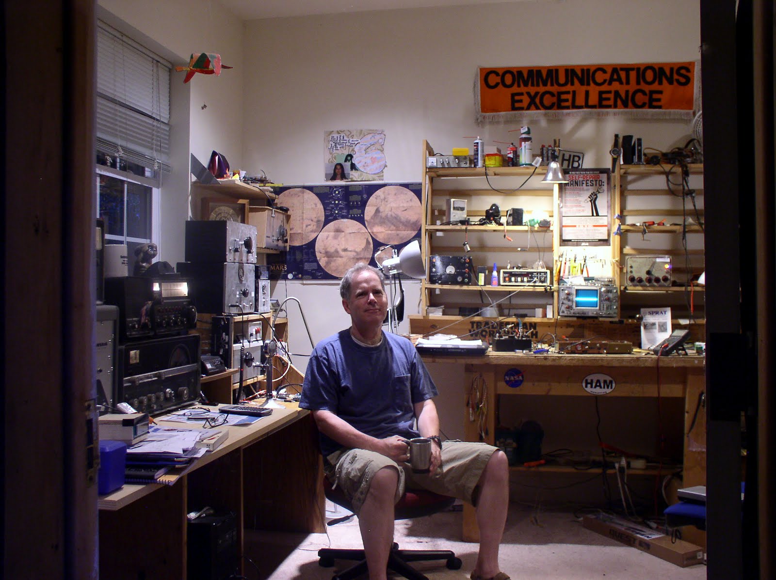
Once again great things are happening in the underground lab of Michael, AA1TJ. Michael has temporarily put aside his work on Iron Pyrite-based receivers, and is now working the world with 50’s era point contact transistors. I can feel the enthusiasm, even all the way over here in Rome. I particularly liked Michael’s description of the QSO in which the other guy heard his backwave. Backwave is the very small signal that is sometimes put out when the key of simple transmitter is up. For example, the oscillator on my old VXO-controlled 6 watter (from “QRP Classics”) ran all the time — I just keyed the amplifiers. Sometimes guys would report hearing some of the RF from the oscillator even when the key was up. (By the way, the term backwave reminds me of a word used sometime by Billy and Maria: backwash. As in, “No Maria, you can’t have a sip of my soda — you always leave backwash!”)

In his e-mails, Michael mentions that the physics of the point contact devices are a bit of a mystery for him. I recall that the book “Crystal Fire” by Riordan and Hoddeson had some pretty good info on how these early transistors worked.

Here are some excerpts from Michael’s e-mails on this project:

I haven’t had time to document this pyrite/tunnel diode receiver on account of a phone call that I had two weeks ago from Jack Ward at the Transistor Musuem. Jack approached me with an idea to recreate the first ham radio contacts using transistors. Of course, the point-contact transistors involved are now pretty rare items. No problem for a fellow with a transistor museum though!
Jack kindly sent me a couple of Western Electric, 2N110 “relics.” I had some initial trouble with “squegging,” and I wasn’t able to produce oscillation above 380kHz. To read a recent tale of one fellow’s trouble trying to tame the 2N110, please see
I especially liked where he wrote, “I did seriously consider giving up at this stage and taking up heavy drinking.” ;o)
However, I located an old textbook that discussed circuit design theory using point-contact transistors (the physics of these devices are still clouded in mystery). What I learned made all the difference. A few more hours at the bench and I had an 80m transmitter putting out 10mW.
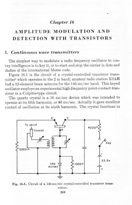
The story gets better though, Ned. A circuit briefly described in another old book really caught my attention. It was pretty much the same circuit as was used by George Rose, K2AH, in his first transistor QSO. Only, a circuit (designed by G3IEE) showed a pair of headphones in dotted lines, next to the collector resistor. The text merely said
“As indicated, the circuit also functions as an oscillating detector type of receivere for local continuous wave operations whith head phones plugged into the collector circuit instead of resistor R3. Good reception and break-in operation were obtained.”
That got my blood moving! Positive results came right away on the bench. The received signals were every bit as strong as with my Reggie and the Cub Scout heterodyne (what I started calling, “Chester,” after the name of the mine where the pyrite was found).
I had my first QSO last week using Jack’s point-contact transistor (made in 1956) in the transceiver designed by G3EII (in 1954). Jim, W1PID, was my first contact. Since then I’ve made over a dozen QSO’s with five different stations.
FYI, I’ll paste a message below that I sent to Jack Ward this weekend. One thing I forgot to add is that W1VZR copied my 10mW signal on his Cake Pan regenerative receiver over in Maine last week. Aside from my three QSO’s with VE3DJX at a distance of 319 miles, the other notable results to-date were hearing both W1DFU and W1PID – in the course of separate QSOs – when they dropped down to an output power of 100mW.
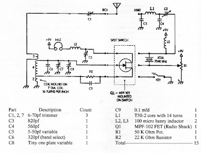
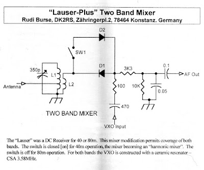
Again, I haven’t had a chance to post much on my web site, but I do have the current schematic up, and you can see both K2AH and G3IEE’s circuits in scans from the old transistor book. G3IEE’s circuit is shown in Figure 16.2 in the second jpeg image.
One more thing, Ned. I hooked up this past week with G3JNB. Victor was one of the fellows (he was only 21 at the time) working with Tony, G3IEE, back in 1954 to make the first-ever, UK ham radio QSOs using transistors. Victor has already posted an envelope containing copies of his log, the QSL card from G3IEE and the original, 1954, Wireless World article describing their results. In the course of our Skype video call last week, Victor held up to the camera the RAF telegraph key that he used for his QSO with Tony. Pretty neat, eh?
I’ve got to get back to work here. Congratulations on getting your Reggie up and running, Ned. I look forward to seeing the photos and I’d surely like to hear about any contacts you make with it. Speaking of which, I have some photos of Jim, W1FMR’s beautifully constructed Reggie that I’ve been meaning to post on my web page. Once I get around to it would you mind if I include one of your photos as well?
Best wishes,
Mike, AA1TJ
Hi Jack,

Yes, I had great fun with our little 2N110’s this past week. Of of now, I’ve had well over a dozen radio contacts with five different stations. I used 10mW of output power to make these contacts. The distances shown are all “as the crow flies.”

W1PID, Sanbornton, NH, 67miles; lowest power used on his end 100mW
VE3DJX, Smith Falls, Onatario, 319 miles; 10watts on his end
W1DFU, Wallingford, VT, 42 miles; his lowest power was 100mW
W1VZR, Limerick, ME, 100 miles; 40w

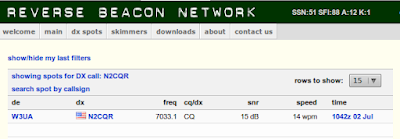
Pete, the last fellow listed, heard the 2N110 while it was running as a “beacon” with a continuously looped Morse code message. Having received my call-sign he located my email address and shot off a reception report. I saw his message pop up on my computer and quickly looked up his telephone number. He was still at his radio when he picked up the phone. I found him pretty excited as my signal strength had sharply risen in the last few minutes. He asked if there was a problem with my keying circuit as he could still hear a faint tone on my frequency when my transmitter should have been silent. “Ha!” sez I, “You’re hearing a 100 microwatt back-wave radiation!” The distance separating us divided by the 100uW power is equivalent to 1 million miles per watt; a very impressive figure!

One more station answered my CQ this past week from near Hartford, CT. However, I can’t recall his call sign and I’m currently at work but my logbook is at home. My output power was up to 17mW during that contact; on account of a temporary change that I made to the circuit. However, pushing the transistor to that power level reduced the quality of the keying, and so I returned to 10mW following that contact (earlier, I’d reported that my output power was 12mW, but a more careful measurement indicated that I was only putting out 10mW).

You might have noticed that I’ve posted the schematic to my web site. However, I expect the circuit will change over the next week, or so, as I still want to tinker with the keying circuit. By all reports my signal is good but it has just a touch of keying “chirp.” Chirp is what hams call a variation in the received signal tone when the telegraph key is first depressed. Again, I expect to have that sorted out before long.

Yes, it was a real pleasure talking with Victor, G3JNB. FYI, I’ll send you copies of all the documents that he provides. He said that he’s including some original data sheets for point contact transistors that he’s held on to these past 55 years. I’ll keep copies and send the originals to you.

I asked Victor if he’d like me to build a duplicate radio for him using the second 2N110 that you sent me. I think he was thrilled to hear my offer. Don’t you think it would wonderful if he, of all people, managed to make a contact using a reproduction of the point-contact transmitter that he and Tony, G3IEE, used in those pioneering days?

The order of business next week is to finalize the circuit design and begin building two identical circuits into permanent radios. Of course, I’ll take time off, now and then, to try and make more contacts. I’m already astonished that it was possible to span a distance of 319 miles (not once, but thrice!) using your ancient transistor relic.

Acting on your suggestion, I looked up the other fellows mentioned in K2AH’s article. It turns out that Tommy Thomas, W2UK, was quite a radio pioneer on VHF.

http://www.infoage.org/html/p-43W2uk.html

Unfortunately, I’ve learned that he passed away not so long ago. The call signs of the other two fellows are not currently in the FCC database (I suspect because they are gone as well). A quick search on the Internet turned up nothing on them.

Victor, G3JNB, remarked that he believes that he is the only one left of his original group of transistor enthusiasts. Doubtless, one reason is that he was only 21 years-old at the time of the experiments with G3IEE.

Victor reports that Tony, G3IEE, worked as an engineer for Mullard. I guess that explains where his transistors came from. Victor used a standard vacuum tube transmitter for his first contact with Tony, but sometime later he built his own one-transistor transmitter following Tony’s design. Victor says that he used it to make one or two contacts across town before he put it on the shelf. Again, I’ll be very interested to see the photocopy of his station log from that period.

One more thing, Jack. I’m fortunate to count George, G3RJV as a pal-o-mine. George is a recently retired Anglican vicar, but he also founded the GQRP; what began as a society of UK amateurs interested in low power operation. Since then, it has become something of an international institution. I had a message of congratulations this week from George; saying that he’s keeping a watchful eye on our project. In return, I inquired if George might be able to put me in contact with folk that might help shed light on what was going on at that time (transistor-wise) in the rest of “Hamdom”. That is, I’d like to assemble a folder on the topic of “first transistor QRP QSOs” for Japan, Western and Eastern Europe, Australia, etc.. I’ll keep you apprised of any news.

That’s all from here, Jack. Once again, I’d like to express my thanks to you for including me in your project. It’s already been great fun and a real pleasure to meet some wonderful people.

Kind regards,
Mike, AA1TJ

My ET-1 / FETer (Transceiver Made with One FET)

Magnificent, don’t you think? This is my version of the ET-1 or FETer. It is an HF transceiver using only one active device — a single MPF-102 Field Effect Transistor. I didn’t have a 4 pole Double Throw switch in the junkbox, but I did have a 4PDT relay, so I used the relay. So far I have only built the receiver. It is working nicely. I was listening to German and Polish stations on 80 meter CW this morning.

I had always wanted to build W2UW’s ET-1… I’ve been reading in “Empire of the Air” the inspiring account of Armstrong’s invention of the regen receiver… Then, along came SPRAT 137 and G3XBM’s FETer. I could no longer resist. Solder was melted.

It is great fun to listen to 80 meters and realize that the only thing between you and the ether is one small FET (you can see mine standing proudly atop the relay!) . Its a lot like using a crystal receiver. That one FET is serving simultaneously as an RF amplifier, mixer and BFO!

On to the transmitter! Thanks to OM Armstrong, to Glen (W2UW), and to Roger (G3XBM).

Minimalist Radio: The ET-1 and the FETer

SPRAT # 137 (Winter 2008-2009) has a number of great articles on minimalist radio — very simple rigs with low parts counts. Roger G3XBM has a very nice re-make of the ET-1, first introduced by Glen Yingling W2UW in SPRAT 108. I remembered Glen’s article — I always wanted to try it. The ET-1 has just one active device: an MPF-102 FET. And it is a transceiver.
The schematic of the ET-1 appears above. I started building mine yesterday. Got the receiver done and — WOW! — heard some 80 meter signals this morning. More to follow…