SolderSmoke Podcast #191 is available:
http://soldersmoke.com/soldersmoke191.mp3
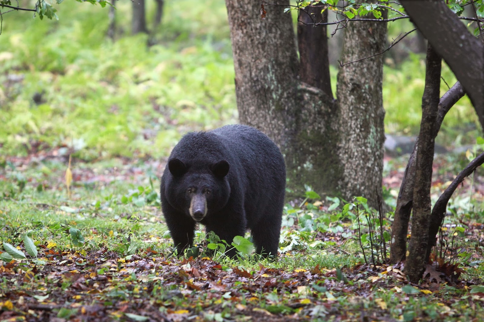
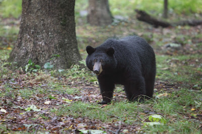
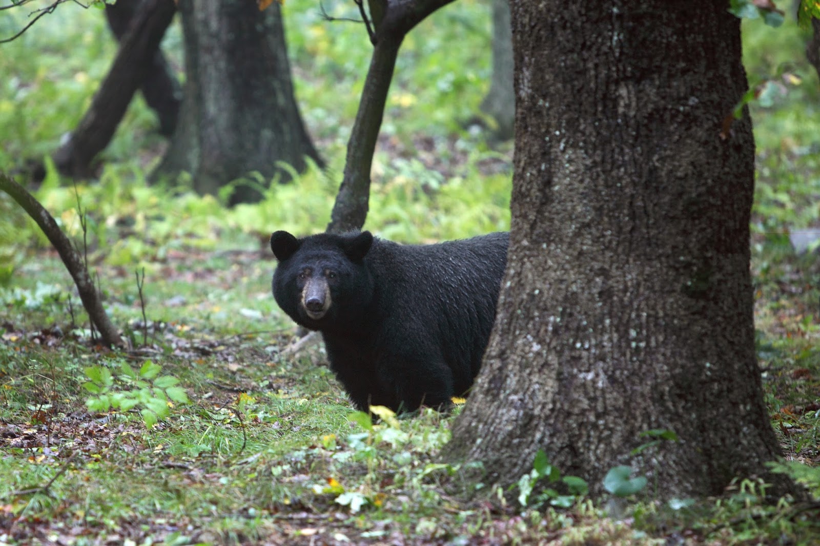
TRAVELOGUE AND FAMILY DOINGS: Pete son’s wedding, Billy’s Birthday, Gonzalo safely home in the Dominican Republic, MORE BEARS IN THE SHENANDOAH WOODS
BIG NEWS: EMRFD LIVES ON! Three cheers for Wes and for Tom Gallagher of the ARRL.
BENCH REPORTS:
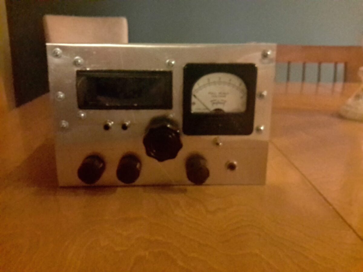
PETE: FPM Rig. Some Halli history. A TRUE RIG! Working Japan.
WITH 600 WATT LINEAR AMPLIFIER!!!!!!!!!!!!!!!!!!!!!!
New FEELTECH Sig Gen.
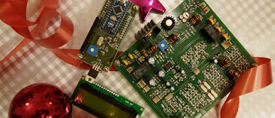
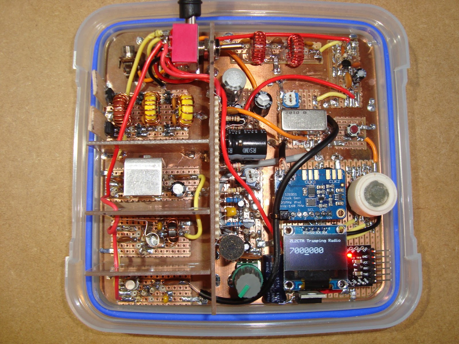
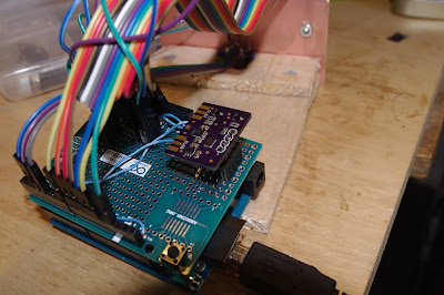
BILL: Farhan’s BITX Module
Built to Mod, built to get you started in homebrew
Very impressive. BITX in miniature. But completely recognizable.
REMARKABLY stable.
Farhan personally checking each one.
Ladies collective doing toroids. DONATION money bought them some Diwali candies!
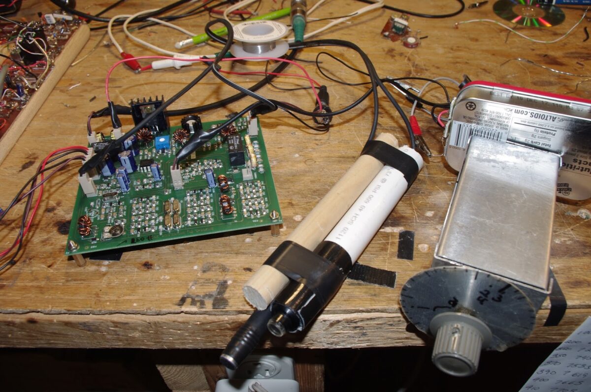
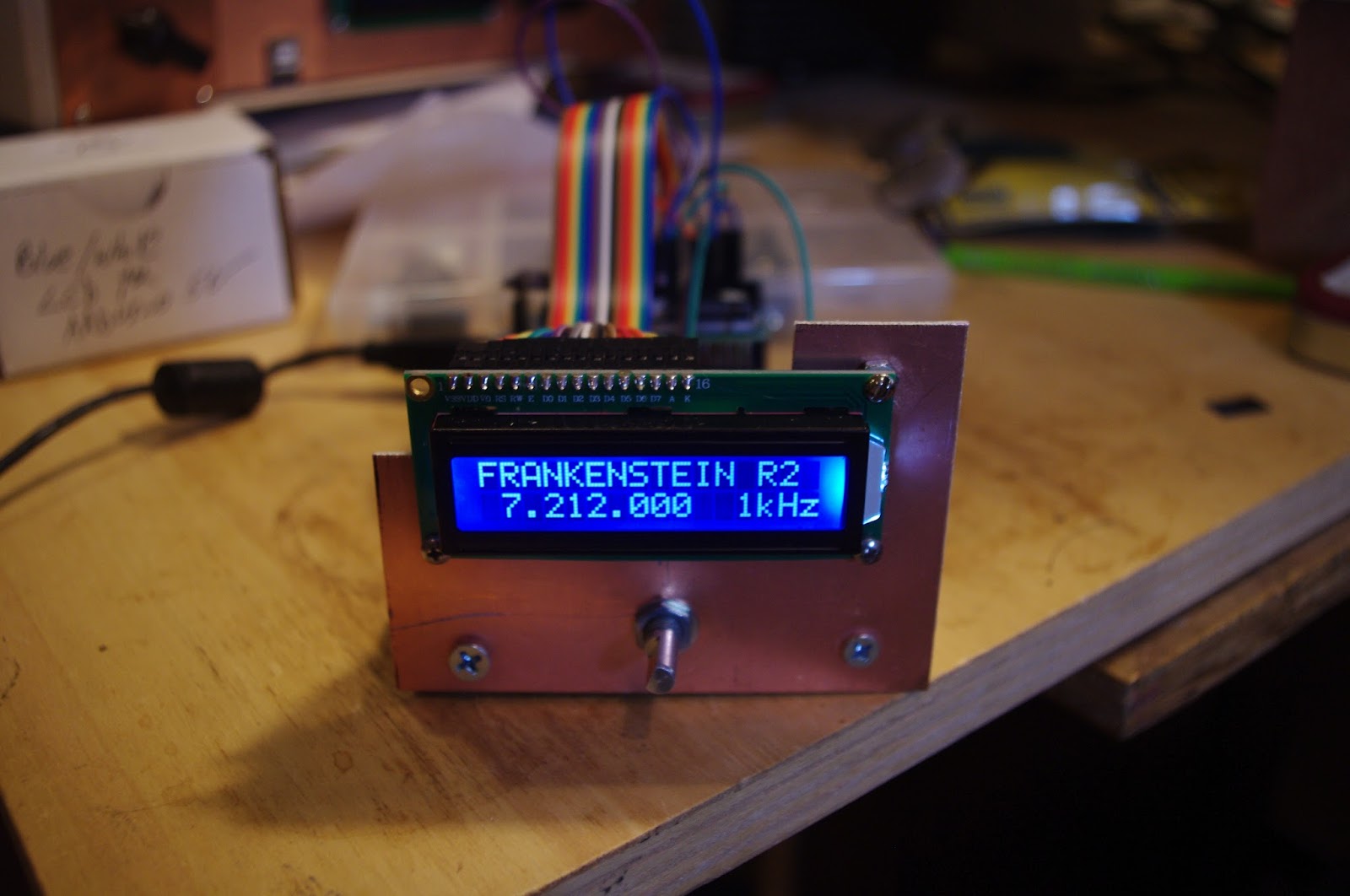
VFO Drift: Will NP0 SMD caps and lower current help enough?
My Analog VFO — BANDSWEEP
QRPppppppppppp with REX’s Hamfest Buddy. Thanks Rex and Bob Crane.
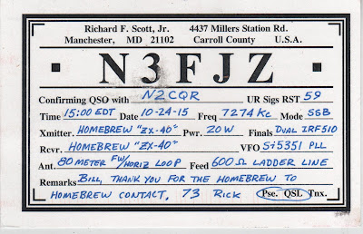
HB2HB with KW4KD
MAILBAG
Jan’s Netherland Mate Mighty Midget
Charlie’s Kiwi DSB
Steve, Donald Fagan, and Jean Shepherd
Rob VK5RC repairs Tek Tube ‘scopes
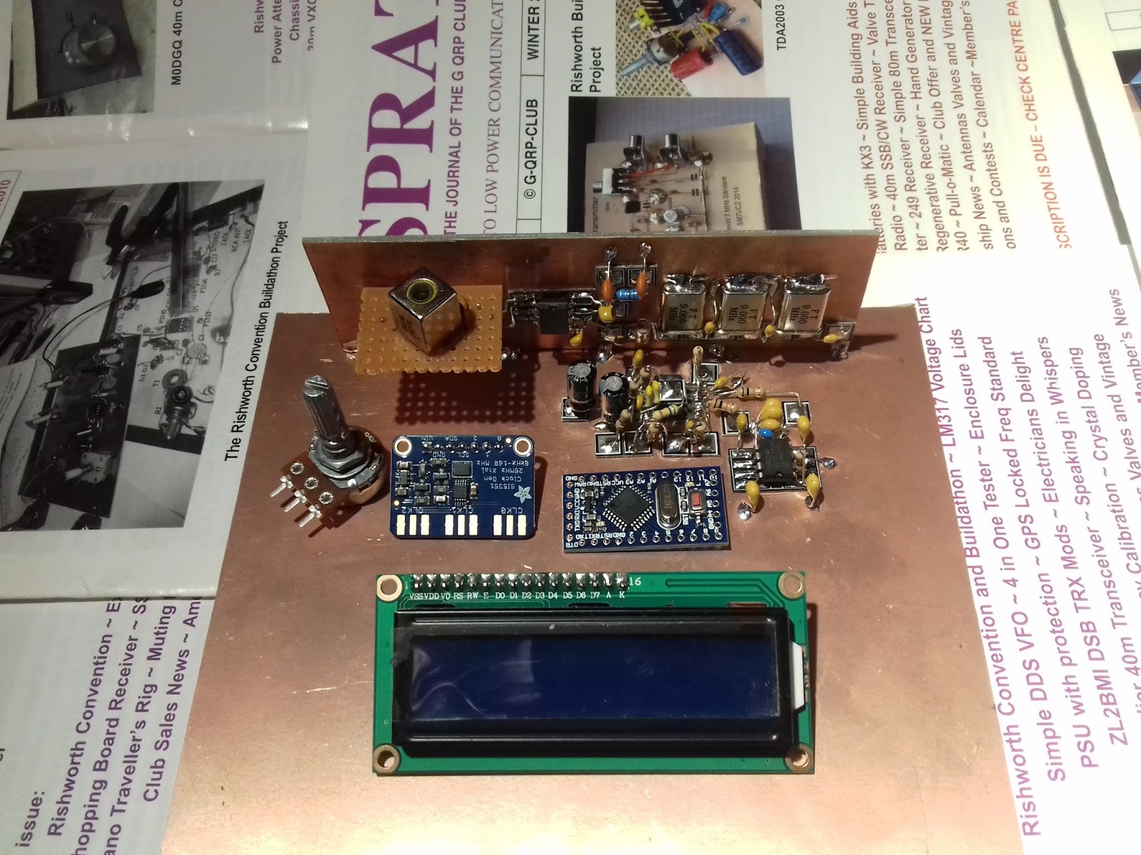
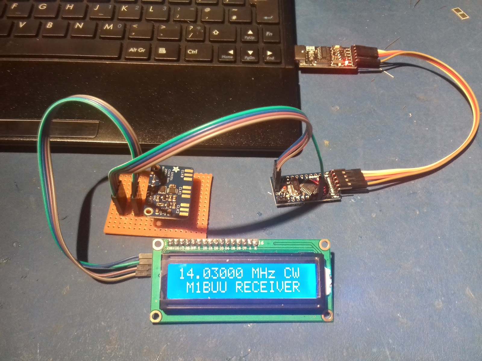
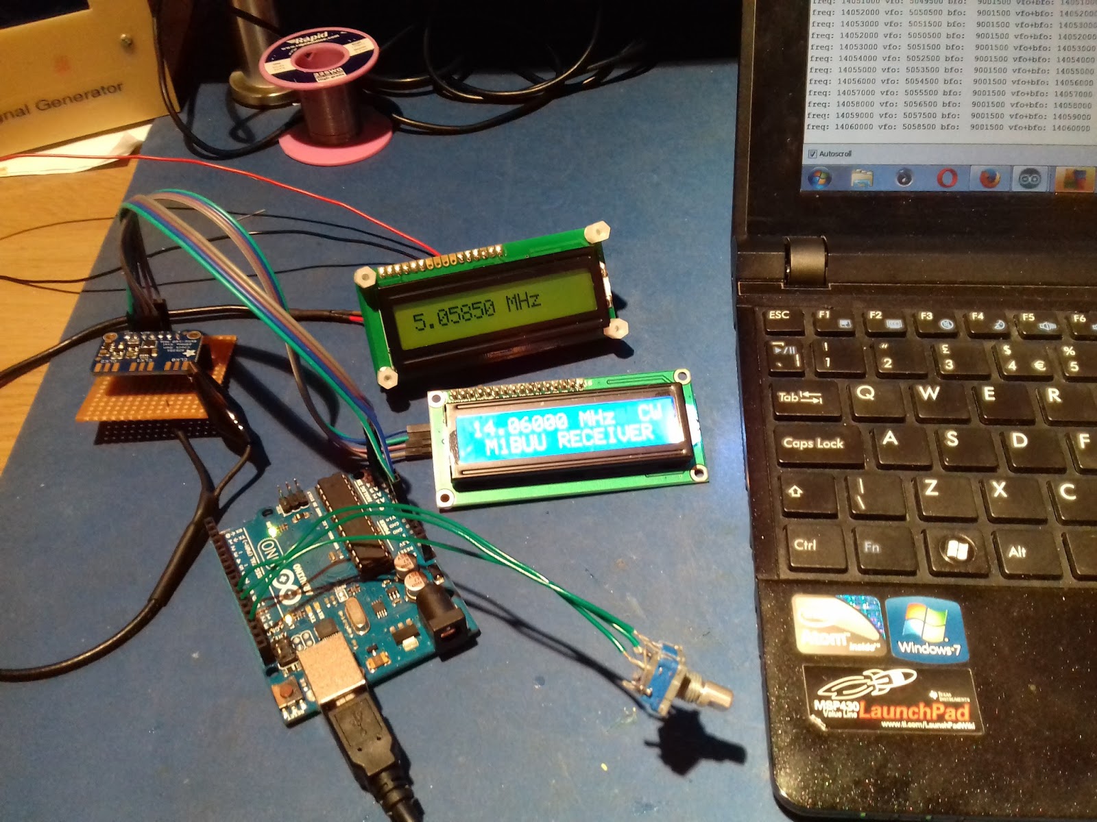
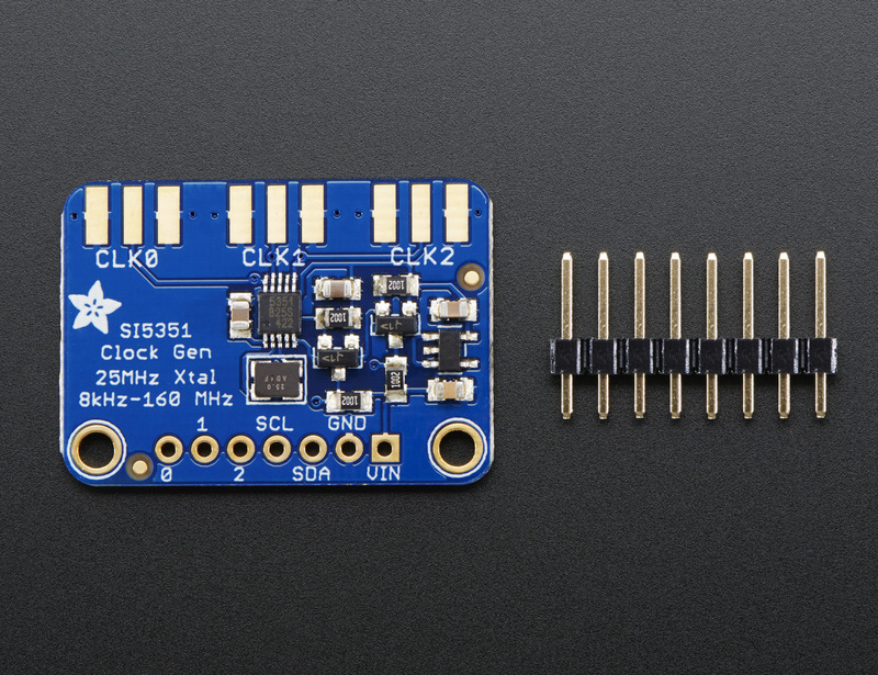
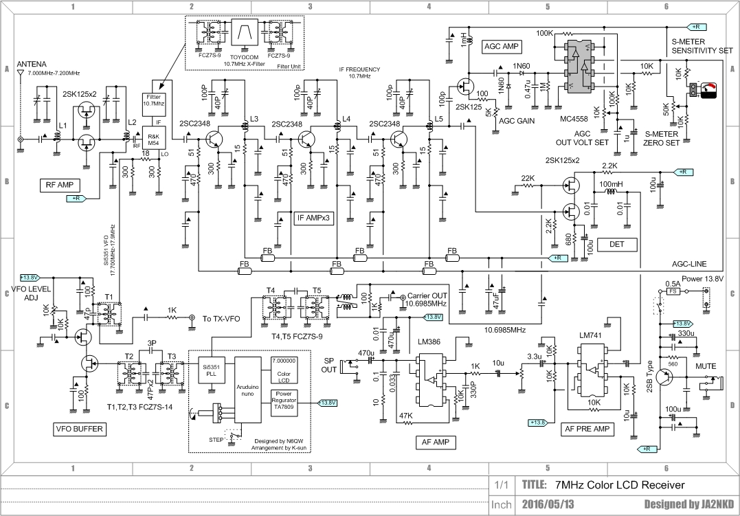
Colin M1BUU Si5351 superhet
Denis Klipa and NRL 3538
Jonathan M0JGH Wizard of Wimbledon Matchbox rig
JH8SST Simpleceiver
Peter Parker Vk3YE Reviews Book
Peter GW4ZUA Welsh LBS
Michael Rainey helping hobbyist in Germany with tuning forks.


