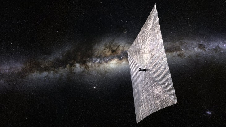
Chinese Micro-Satellite Photographs Eclipse — FROM THE MOON

Back in October 2018 I posted about this Chinese satellite:
According to report by Xinhua, a microsatellite developed by the Harbin Institute of Technology in northeast China’s Heilongjiang Province, which is now orbiting the moon, captured mesmerizing photos of Earth during the solar eclipse in the early hours of Wednesday (Beijing time).
It is to be noted that the microsatellite, weighing 47 kg and named Longjiang-2, was sent into space on May 21 last year, along with the Chang’e-4 lunar probe’s relay satellite dubbed as “Queqiao” and entered lunar orbit four days later.
According to the research team from the Harbin Institute of Technology, the microsatellite carries a mini CMOS camera that only weighs 20 grams, which makes it easy to operate, and it can take pictures at short intervals.
“Since the camera uses an automatic exposure mode, the camera’s field of vision must contain a certain area of the moon to realize correct exposure. When the recent total solar eclipse occurred, the orbiter was flying over the far side of the moon. In the few minutes before and after the moon blocked the earth, all the conditions were right to take the pictures,” Xinhua further quoted the team as saying.
According to the team, to avoid becoming space rubbish, the microsatellite will be controlled to crash into the moon after it stops operation at the end of July.
As per Xinhua, the team cooperated with amateur radio operators in Spain and Germany in taking and receiving the photos. Nearly two pictures taken by the microsatellite during the solar eclipse were sent back to Earth on Wednesday.

LightSail 2 — Solar Sailing Cubesat with a Beacon on the 70cm Band

Once deployed, LightSail 2 will automatically transmit a beacon packet every few seconds, which can be decoded into 238 lines of text telemetry describing the spacecraft’s health and status, including everything from battery status to solar sail deployment motor state. Every 45 seconds, the spacecraft will transmit “LS2” on the spacecraft’s frequency of 437.025 MHz, within the Amateur Radio 70-centimeter band.

Antuino’s Cubesat Origins, and How it Works (with video)

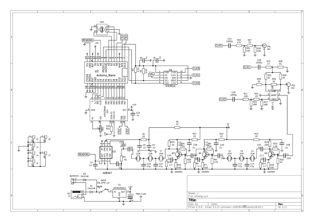
In a series of e-mails to the BITX20.io group, Ashhar Farhan VU2ESE provided background information on the origins of his new “RF Lab in a Box’ — the Antuino. He also explained how the device performs the SWR meter, Power Meter and Scalar Network Analyzer functions.

Farhan’s Antuino Page: http://www.hfsignals.com/index.php/antuino/

Dec 27, 2018 to BITX.io

peeps,


while trying to measure the swr on the cubesats, i figured i couldnt use any of the analyzers i had access to. they were simply too big to be stuffed inside a 10 cm cube. my simple resistive bridge was too insensitive for any reasonable work. so, i sat down and made an antenna analyzer from a spare raduino.

the code is wobbly and just about enough to get my work done. it works on a superhet principle. this is not my clever idea, rahul had mentioned this approach taken by a russian builder. i havent seen the original design. it would be interesting if rahul or someone can point me in the right direction.

the code and a pdf of the circuit is on https://github.com/afarhan/antuino. i am attaching the circuit for the lazy bones.

have a great holiday and get some dx !!

– f

Dec 28 2018

Jerry,

first, thanks. there is substantially your code in there.

second, onto the circuit. it uses two clocks. not three. the third is a spare output. more on that later.

the circuit here uses a resistive return loss bridge. the clock 1 drives the bridge through the R22 to a low level of -10dbm. If the bridge is perfectly balanced (that is, the antenna, R21, R29, R16, all the four are the same ohms), then, there will be no RF developed across pins 3 and 4 of the ADE mixer. Under ideal match conditions, there is no RF across the R26. As the mismatch increases, so does the RF across R26.

We could directly detect the voltage across the R26 with a diode detector. This is quite a popular configuration with most of the simple resistive kind of SWR bridges (like the one designed by Dan Tayloe). This simplicity comes at a cost. The problem is that the detector responds to all the RF between the arms. For instance, if another ham down the block starts to transmit, that energy will show up across the R26 and you will get crazy SWR. I had that problem with broadcast FM showing up on my 7 MHz dipole! Even if there was no RFI from elsewhere, harmonics and spurs from your own transmission can show false readings.

Here is an example: a 7 MHz transmitter with a 14 Mhz harmonic that is 20 db down is connected to a 7 MHz dipole. The dipole is perfectly tuned to show 1:1 SWR, hence, it should show no RF across R26. However, as the antenna is reflecting back the 14 MHz energy, the 14 MHz shows up across the R26.

What’s the solution to get a clean dip?The solution is to substitute a simple detector like a diode detector with a simple receiver that is tuned exactly to the frequency that you want to measure the antenna at.

So, the ADE-1 mixer, Q2, Q1 together form a very simple superhet receiver with 25 MHz IF andCLK2 as the local oscillator. The RF at the IF is directly detected and converted to db range with the AD8307. This simple configuration makes this a very powerful instrument.

Here are things you can do with it:

1. Switch off the CLK1, now you have a receiver that can very accurately measure RF levels at any specific frequency in db range. For instance, you connected your transmitter with a suitable RF attenuator to P3, you can tune to various harmonics and measure them very accurately. If you inject a two tone signal into an amplifier, you could easily measure the IMD and IIP3.
2. With the CLK1 on, the instrument now measures the return loss. you can measure the SWR of an antenna, S11 parameters of an amplifier, filter, etc.
3. With CLK1 off, CLK 2 on, the CLK2 can now tune to the frequency tuned in by the receiver’s LO (CLK0). By connecting a device/filter between P3 and P4, you can sweep it to measure the gain, frequency reponse.
4. As the diode mixer (ADE-1) has harmonic response, a local oscillator at 135 MHz, will also convert a 430 MHz signal into 25 MHz IF (430 – (135 x 3)). This is possible because we are driving the diode mixer with a square wave from the Si5351 and the local oscillator at 135 MHz also has a 405 Mhz harmonic in it. Hence, the range of this instrument extends to UHF.

The ADE-1 mixer is quite similar to the ubitx mixers. You could even use ubitx kind of discrete version of a diode mixer, it doesn’t work too well beyond 50 MHz. The pins 4 and 3 of the ADE-1 are the primary winding of the RF-input side transformer. The documentation recommends that we must ground 4, but that is not essential. We need a differential drive between those two pins, that is what the bridge provides anyway.

73, f

jerry,

i built it so i could stuff it inside the cubesat to measure the antenna. an external spectrum analyzer and its cables were upsetting the RF model hence, i needed something that could read the return loss sitting inside the cubesat. then, i borrowed by daughter’s DSLR with a monsterous tele lens and sat 100 meters away to read the the LCD display as it swept through the range.
the analyzer was removed once we knew the correct dimensions and the actual payload went inside the bird.
– f

SolderSmoke Podcast #211 — Malicious Code! Spaace! Vintage Sideband! MAILBAG

27 April 2019

SolderSmoke Podcast #211 is available

http://soldersmoke.com/soldersmoke211.mp3

Pete NOT quitting podcast! Malicious code case RESOLVED!

Ambiguity and the Digi-Analog Divide

Edwin Howard Armstrong biography

SPAACE!
Apollo 11 50th Anniversary
Oscar 100 in Geostationary Orbit. Why can’t we have one too?
Farhan puts AISAT in orbit. FB!
Space is difficult
SSTV from the Space Station

Pete’s bench report.

Vintage Sidebanders
Recording of Midwest Vintage SSB “tune up session”
Vintage rigs that sound bad
Distorted views on “distortion”

Bill fixing old Bose Wave Radio

NOT GOING TO DAYTON. AGAIN! But SolderSmoke rep will be there

75 meter secrets of success (timing is everything!)

MAILBAG

Steve N8NM sends me FB National Dial
Steve N8NM aspires to complexity — enough of this simple stuff!
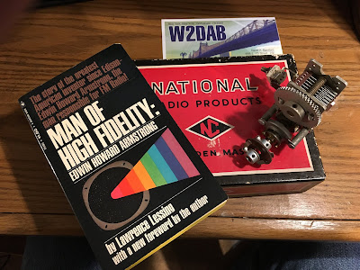
Dave W2DAB goes to Columbia U session on Armstrong, sends FB book.
Jim W4JED — reports of QCX sideband a bit exaggerated. Where is Allison?
Rob Powell wins beret challenge. VK2TPM and VK2BLQ also win. CONGRATS!
Colin G3VMU sends nice 1930s radio picture
Alan WA9IRS sends diagram of digi radio signal flow. CLEAR AS MUD!
Chris KD4PBJ Grandmother worked at Hammarlund.
Steve NU0P sends info on Art Collins and the Apollo moonshots.

Circuit for Farhan’s Satellite — Arduino in SPACE

Farhan sent me the schematic of the AISAT amateur digital satellite that went into orbit on April 1, 2019 from India. He notes that the circuitry is very simple. Indeed, it reminds me of the very simple but effective circuitry we saw in satellites in the early days of the space age. Beautiful simplicity, with an Arduino on-board. And it is great to see that Farhan did not forget the low pass filter. FB OM.

Packets from Farhan’s Space Ship

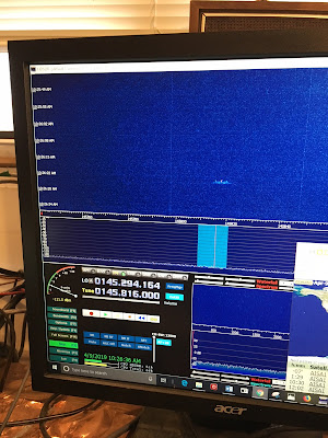
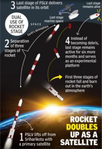
Farhan’s AISAT flew over this morning. Using HD-SDR software, an RTL-SDR Dongle, and my Dominican Republic refrig tubing quad I was able to capture some the packets. Above you can see one of them, floating like a flying saucer in the waterfall. Pretty amazing that that signal came from a machine put in space by our friend Farhan.

Congratulations to Farhan on New Amateur Satellite Launched 1 April

This is not an April 1 trick. Farhan and Exseed Sat have put another bird in orbit.
Details here:
http://amsatindia.org/

This site in Argentina gives pass information:
http://amsat.org.ar/pass?satx=aisa1

I will be listening tonight!

Congratulations Farhan!

More info:


Amazing New Geostationary Amateur Satellite — LISTEN ONLINE!

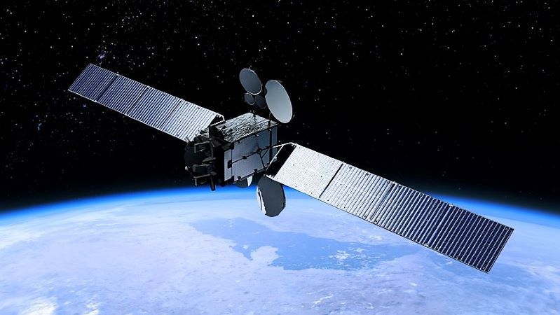
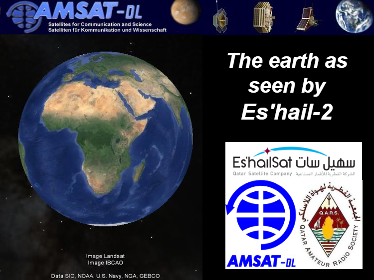
Wow, quite a step forward in the amateur satellite world. Qatar and AMSAT-Germany have collaborated to put an amateur radio repeater in geostationary orbit. That’s pretty amazing. Read more here:

https://hackaday.com/2019/03/18/eshail-2-hams-get-their-first-geosynchronous-repeater/

Read about a group of Norwegian students working on a satellite station for this bird:

https://www.la1k.no/2019/02/20/getting-ready-for-e%CC%B6s%CC%B6%CC%B6h%CC%B6a%CC%B6i%CC%B6l%CC%B62%CC%B6-qo-100-part-2-how-we-did-it/

And this is really fun: LISTEN TO THE DOWNLINK LIVE VIA WEBSDR!

We can’t hear this thing from North America — it is flying over the Congo. But stations in its footprint are putting their receivers online — you can listen to the 10 GHz downlink via WebSDR:

UK WebSDR: https://eshail.batc.org.uk/nb/

Brazil WebSDR: http://appr.org.br:8902/

Ghost Ship: Oscar 11 Tumbles Through Space

First — Happy Boxing Day to all our UK and Commonwealth friends.

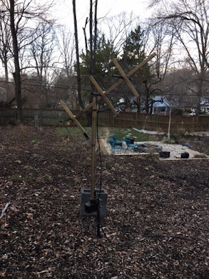
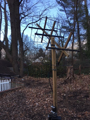
Oscar 11 is a UK-built amateur satellite launched in 1984. It has been dead (well, almost dead) for many years. But when the sun shines on the solar panels, it wakes up and transmits. I’ve been able to hear it and — more usefully — see it on my RTL-SDR HD-SDR receive system. My antenna is my re-born (from the Dominican Republic) three element homebrew 2 meter cubical quad (see pictures below).

I’m sorry the video is a bit out of focus, but you can clearly see the trace of the signal from the satellite. Realize that my HD-SDR software is about 10 kHz off calibration. You can see the Doppler shift, and you can see the signal fading in and out as the old satellite tumbles through space. Any ideas on what the other signals seen off to the side are? Is anyone else listening for Oscar 11?

https://amsat-uk.org/satellites/telemetry/uosat-2-oscar-11/

https://en.wikipedia.org/wiki/UoSAT-2

http://www.dk3wn.info/p/?cat=47
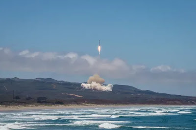
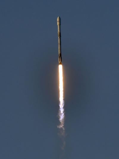
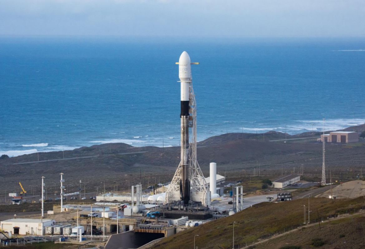
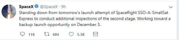

UOSAT_OSCAR-11

Launch Day! Godspeed Exseed! 1:31 pm Eastern time. Video links here.

Farhan posted this message and the above video to Facebook today (I have the video cued up to around the 5 minute point):

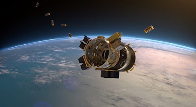
We are all set for the launch of ExseedSat… There are two tiny switches at the bottom of the satellite that keep the satellite switched off while it stays in it’s container. Once the satellite is ejected, the switches are released and the satellite wakes up.
There are 36 satellites on this launch, some belong to close friends in the satellite fraternity. We wait for all the satellites to drift out and after 45 minutes, the antennas are depolyed and we will start beeping signals home.
Here is a test of that process. You can skip to the fifth minute to watch the antenna depoly .


I really like the tape measure antenna. This recalls the earliest OSCAR satellites. And let’s not forget that OSCAR 1 also launched from Vandenberg. So there a lot of good tradition flying with Farhan’s bird.

Press reports indicate a launch time of 1:31 pm Eastern time today. I think you can watch it live through the video window below. Or try this link:

https://www.youtube.com/watch?v=Wq8kS6UoOrQ

Cubesat Launch Now Scheduled for Sunday Morning (California time)


Here is an update from the San Luis Obispo News:
It kind of makes you wish you were out there…


https://spacenews.com/dedicated-rideshare-falcon-9-launch-raises-satellite-tracking-concerns/

https://www.theverge.com/2018/12/1/18114894/spacex-falcon-9-reusability-sso-a-mission-rideshare-satellites

Totally Absurd — Farhan Being Questioned in a Police Station

I walked into the shack this morning hoping to read good news about the InSight landing and the impending launch of Farhan’s satellite, but instead I found this message from Farhan in a police station. This is really absurd and disheartening. Someone (not Farhan!) altered the Indian flag and put it into an image of Farhan’s CubeSat. So with 24 hours to go before the launch, our friend Farhan finds himself in a police station.

Stay strong Farhan! You have a lot of support around the world.

The Max Valier Satellite Flies Over, Sending CW

I understand the launch of Farhan’s CubeSat has been delayed a few days. That’s the way it works in the rocket launch biz –patience is required. In the meantime, I’ve been practicing with my receive system. Today at 1000 local the Max Valier satellite flew to my west. It rose 78 degrees above my horizon to the W NW. I left my three element quad pointed in that direction and waited for the satellite (which had been launched from India) to fly through its pattern.

The CW beacon was quite strong, very visible and audible through my RTL-SDR dongle and HD-SDR software. You can see it and hear it in the video above. There is something quite charming about this very personal Morse message coming down from orbit and then passing through all that digital technology.

More info on the satellite:


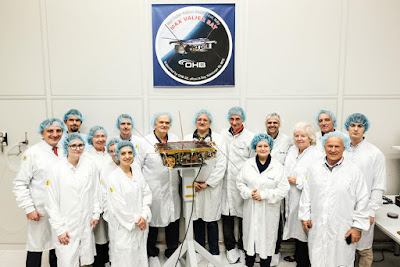
“Max Valier Sat” is an amateur satellite built in cooperation by:

  • “Max Valier” High School in Bolzano/Bozen (Italy)
  • OHB System AG from Bremen (Germany)
  • Max Planck Institute for Extraterrestrial Physics from Garching (Germany)
Its main payload is an X-Ray telescope devised and made by MPE. Data generated by this detector will be transmitted, together with housekeeping data, over an amateur radio link with frequency 145.860 MHz.
A second payload is an amateur radio beacon transmitting a message in Continuous Wave. The beacon’s frequency is 145.960 MHz
“Max Valier Satellite” was launched by the Indian Rocket PSLV-C38 on June 23, 2017 at 9:29 am IST (05:59 am CET) from Satish Dhawan Space Centre.
More tech details:
Regarding the CW beacon:

Beacon by Holger Eckardt DF2FQ:

  • Transmit frequency is 145,960 MHz (IARU and ITU coordinated).
  • Modulation is CW:
    • Duration of one dot is 114 ms.
    • Duration of one dash is 342 ms.
    • Interval between words is 1881 ms.
    • Interval between repetitions of the message is 6000 ms.
  • The beacon transmits Max Valier Sat’s call sign and a greeting message.
  • Transmitting power is 500 mW.


And who was Max Valier? Quite an interesting fellow:

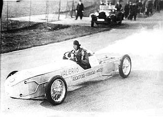
Max Valier in his Rocket Car in 1930

From BITX to SpaceX: Falcon 9 To Launch Farhan’s Cubesat on Monday (video)

  1. https://www.rocketlaunch.live/launch/spaceflight-sso-a-su

    will carry a live feed of the launch


  2. SpaceX will live-stream the launch as well on their YouTube stream. Also – this will be the first SpaceX booster to fly three times, and the first to launch from all three SpaceX pads.

    https://forum.nasaspaceflight.com/index.php?topic=46756.0

Special thanks to Dave Bamford for the BITX to SpaceX line!