Steve “Snort Rosin” Smith: Silver-Tongued Devil! Dual-band “Vlad the Inhaler” RX

You’ll see in the comments attached to my last blog post that our man on the left coast, Steve Smith, gave that cute little Doug DeMaw/Vlad Polyakov receiver a name that might set American-Russian ham relations back a bit: He called it “Vlad The Inhaler.” Good one Steve! (But you might want to stay out of the diplo game!)

It occurred to me that with the installation of one little switch in the diode part of the circuit, we could turn this into a dual-band RX. Take a look here:

http://soldersmoke.blogspot.com/2010/03/polyakov-plus-dual-band-receiver-with.html

Check out “SolderSmoke — Global Adventures in Wireless Electronics”
http://soldersmoke.com/book.htm

Royal Order of the Sputnik Clone Chasers

Kettering Group, UK


From the Chief Designer (AA1TJ):

Fellas,

I came across an online blurb for the recent book, Sputnik: The Shock of the Century, by Paul Dickson; a worthwhile read, judging from the introduction and first chapter.

http://www.sputnikbook.net/intro.php

“Someone brought out a shortwave radio, and soon a beeping noise filled the room. A Russian scientist, Anatoli Blagonravov, confirmed it was Sputnik. “That is the voice,” he said dramatically. “I recognize it.” John Townsend Jr., one of the scientists at the party, recalled watching Blagonravov: “I knew him quite well, and I could tell that he was a little surprised and quite proud. My reaction was ‘Damn!'”

And so an abstraction now had a voice. It also had a name – Sputnik.

Many of those at the party adjourned to the Soviet Embassy’s rooftop, attempting to view Sputnik with the naked eye. Several of the American scientists drifted over to the American IGY headquarters in Washington, where they began speculating on what impact the satellite would have. They feared that the American people would be disappointed.

It also dawned on them that they had better start tracking the satellite’s orbit. They got in touch with the American Radio Relay League in West Hartford, Connecticut, asking its 70,000 members-all “ham” radio operators-to lend a hand and help track the Sputnik. In less than twenty-four hours, reports on the satellite were coming back to the National Science Foundation, where a temporary control room had been established. Eventually, these hams and other amateur and professional trackers would consider themselves part of a great international fellowship known as ROOSCH, or the Royal Order of Sputnik Chasers.”

That’s right guys…ROOSCH…the Royal Order of Sputnik Chasers. And to think that fifty four years later a second great international fellowship would rise from the ashes…ROOSCCH, or the Royal Order of Sputnik Clone Chasers! ;o)

(BTW, October 4, 1957 is an important date in American history for a second reason. On that evening the first episode of Leave it to Beaver made its debut.)

………………………………………..

I thought we should also at this point remember the intrepid lads of the Kettering Group, pictured above. (Some of those dudes look like they would have been right at home in “Leave it to Beaver.”) For more info on their amazing Sputnik adventures go here:
http://www.svengrahn.pp.se/trackind/getstart/oldcyts.htm
and here
http://www.svengrahn.pp.se/trackind/trackin1.htm#KEttrack


Check out “SolderSmoke — Global Adventures in Wireless Electronics”
http://soldersmoke.com/book.htm

Sputnik Madness! But was it CW? or AM?

Our worldwide team of Sputnik enthusiasts continues to seek out the elusive schematic diagram of the spacecraft’s 20 MHz transmitter. American, Cuban, Russian and German radio amateurs are involved. Recently Bruce, KK0S, visited the Kansas Cosmosphere in an effort to get a look at the innards of Sputnik’s “flight spare.” The picture above is his — it shows the Sputnik antenna connection. (More pictures from Kansas here: http://s747.photobucket.com/albums/xx120/trader_vic/Kansas%20Cosmosphere/)
There was bad news and good news from the visit: The bad news was that the spacecraft on display was a hollow sphere. The good news is that the internal parts –including the transmitter — might be in storage someplace, just waiting for our reverse engineering. Stay tuned (to 20 MHz!).

Speaking of which, I have a question: OK so the crafty Soviets picked 20.oo5 MHz for some good reasons: Being so close to the WWV freq, it would be easy for hams and SWLs to find it with precision. In the November/December 2007 issue of “Break In” (from NZ — thanks Jonathan-san!) ZL3DW notes that this frequency selection would allow a receiver set to exactly 20 MHz to “produce an audio tone plus or minus the Doppler shift without ever going through zero beat.” But zero beat with what? Most of the receivers out there would not have had BFOs, right? So the Soviets wouldn’t have been using ordinary CW, right? Were they using AM, with the beeps produced by an audio oscillator modulating the carrier?

Here is a update from our Chief Designer, Comrade Mike, AA1TJ:

I currently have a prototype for a simple “Sputniker” transmitter on the bench using a 1sh29b in the oscillator and a 1p24b working as the PA. As in the original, the input DC PA power is 1watt. The crystal-controlled oscillator uses an inexpensive ESS 21.060kHz xtal. So far, all systems are GO.

BTW, here’s an example of how inexpensively these lovely little tubes may be purchased. Oleg, RV3GM, and his pals might be able to do even better.

Although there are only so many ways one can build a two-tube, crystal-controlled MOPA transmitter, we’d still very much like to nail down the original transmitter circuitry. Bruce, KK0S and Peter, DL2FI are following up leads to that end.

Once we’re a bit further along I’m hoping that someone will step-up to produce a kit. Actually, last evening someone raised their hand to ask if a kit were already available.

Dasvidania,
Mike, AA1TJ

Beautiful Shuttle-ISS Shot

What a beautiful shot. It was taken on May 23 by Italian astronaut Paulo Nespoli from a Soyuz spacecraft. Bravo Paulo! Bella figura!

For a better (high res) view and more details, go here:
http://news.discovery.com/space/big-pic-shuttle-endeavour-docked-space-station-110607.html

The digipeater on the ISS has been picking up my little 2 meter APRS sigs and sending them back down.

Searching for the Sputnik Schematic

Mike, AA1TJ, has launched (!) yet another intriguing project. See below. In an effort to come up with the actual Sputnik schematic, I have thrown down the geek gauntlet to our fellow nerds at sci.space.history:

Greetings Space Historians!
We are a group of radio amateurs and we probably rival you in our
technical geeky-ness. We are now involved in an effort to re-create
and put on the airwaves replicas of the 20 MHz transmitters used in
Sputnik 1. (We will use the amateur radio 21 MHz band).
We are trying to find a schematic diagram for the transmitter. Can
you help us? Thanks.

————————
Gentlemen,

Arnie, CO2KK, told me last night that as a 15 year-old boy he’d made
it into the newspaper by picking up Sputnik’s signal on his Hammarland
Super-Pro receiver.

Don Mitchell – a physicist now retired from the Bell Labs – also wrote
last evening to ask if I knew of a schematic diagram for the two
transmitters used on Sputnik-1. Mr. Mitchell maintains an informative
web site on the topic of Sputnik. Here, for example, is the link to
his page on the first of the series of “Travellers” to be lofted into
orbit in late 1957 into 1958.

http://www.mentallandscape.com/S_Sputnik1.htm

To the best of my knowledge the schematic for what may be the most
famous QRPp transmitter has never been published. It’s a shame,
particularly as it would have been great fun to build an approximate
replica for use on the ham bands

However, I woke up this morning wondering why should we allow the lack
of an original schematic to stop us when there’s plenty of descriptive
evidence available? “Spaceflight Magazine,” for example, published a
wonderful article on the 50th anniversary of Sputnik. The story was
pieced together from original documents over a period of 20 years. You
may read the article here

http://faculty.fordham.edu/siddiqi/writings/siddiqi_sputnik_history_2007.pdf

“The two D-200 type radio transmitters operated on frequencies of
20.005 and 40.003 megacycles at wavelengths of 15 and 7.5 m. These
transmitters (which obviously used vacuum tubes) each had a power
intake of 1 watt and provided the famous “beep-beep-beep” sound to
Sputnik. The signals on both the frequencies were spurts lasting 0.2
to 0.6 seconds, and carried information on the pressure and
temperature inside the satellite; one set would transmit during the
“pauses” of the other.”

“Despite objections from just about everyone, Gringauz insisted that
PS-1 carry a high frequency transmitter (the 20.005 MHz transmitter
operating in the decameter waveband) in addition to the VHF
transmitter (which had been commonly used on Soviet ballistic
missiles). …In the end, Gringauz won over his opponents, partly
because everyone agreed that a high frequency
transmitter would ensure that the radio transmissions would be heard
around the world. The transmitter hardware was built by one
of Gringauz’ youngest engineers, Vyacheslav Lappo…”

>From other sources we know the transmitter used vacuum tubes rather
than transistors. This site mentions that when the received signal
level
was quite strong, the presence of a back-wave while the other
transmitter was keyed could be noted.

http://www.amsat.org/amsat/features/sounds/firstsat.html

The RF oscillator, at a minimum, must have been free-running. So,
we’re talking a vacuum tube crystal-controlled oscillator and a PA
having an input power of 1 watt. They may have used a PA driver stage,
or perhaps a frequency multiplier stage. If they did use a multiplier
then it must have been allowed to free-run as well. But given the
battery drain considerations, I would have done my best to reduce the
number of vacuum tube heaters, or filaments to a minimum. As such, I
think there’s a fairly good chance this was a simple, MOPA design
(oscillator-> PA).

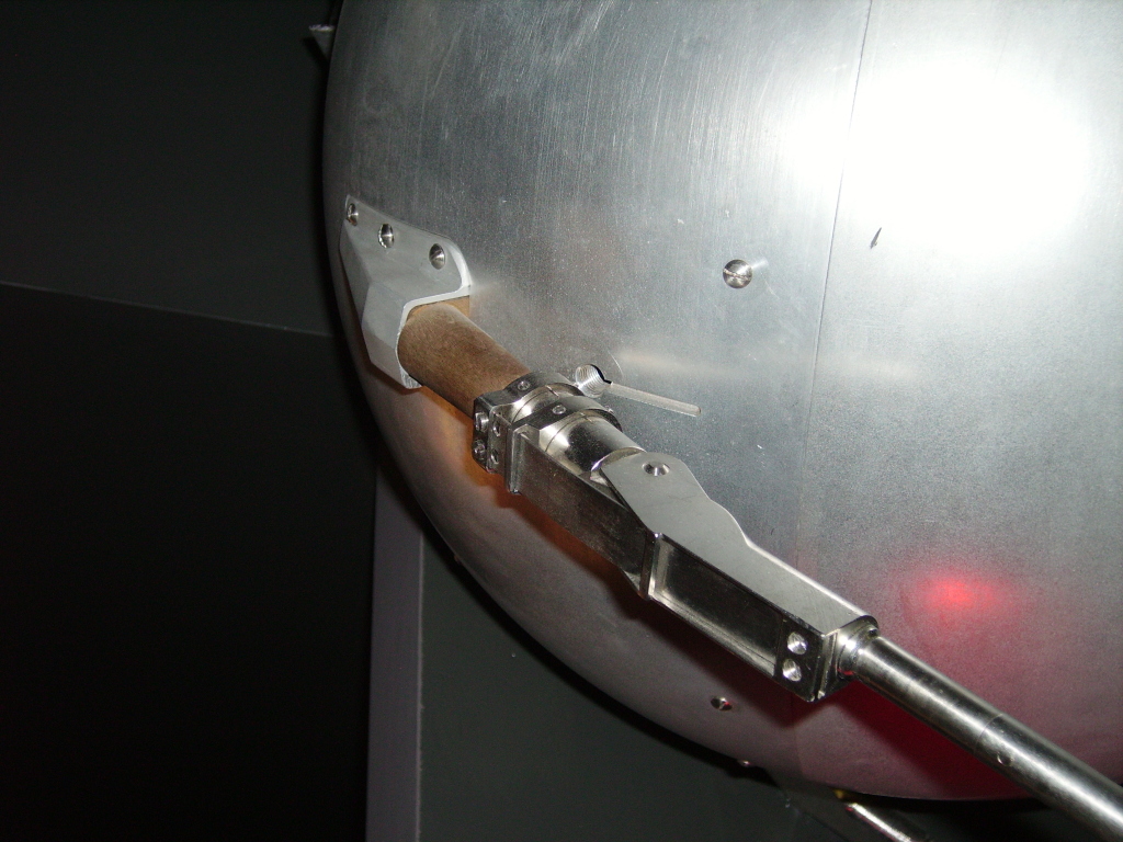
I found what might be a photograph of the transmitter on page 26 of
the December 1957 issue of the Soviet “Radio Magazine.” Perhaps our
Russian speaking group members can confirm this and provide us with
other clues appearing in the article text? The magazine can be
downloaded at

http://publ.lib.ru/ARCHIVES/R/”Radio”/

Click-on ”Radio”,1957,N12.[djv].zip. The “zipped” December issue
appears in DJVU format. Don’t miss the nice Sputnik cover art.

This re-post talks about the center-fed Vee dipole used (the 15m
transmitter used the 5.8meter dipole) among other things.

http://hamradio.mybb.ru/viewtopic.php?id=625

Getting to get the point, this morning I woke up thinking about how
plentiful vintage Russian military tubes are these days. Remember how
inexpensive US military surplus used to be? That’s how it is right now
with Russian components (and the characteristics of some of these
tubes are simply amazing). All I can say is get ’em while they’re hot,
as it surely won’t last forever.

It also came to me that Expanded Spectrum Systems sells an HC49
crystal cut for 21060kHz for two and a half-bucks each.

Finally, I remarked to myself that propagation-wise, 15m may well be
open for business come the 54th anniversary of the launch of Sputnik-1
next October the 4th.

You’ve probably guessed by now what I’m going to propose. We have
plenty of time to throw together a simple 15m CW vacuum-tube
transmitter having an input power of 1w or less. We could use any
tubes that we like but I’m going to build mine using 1950’s vintage
ex-Soviet devices. I plan to power mine with one or two of those
ubiquitous 12V sealed-lead-acid batteries. I’ll VXO my crystal and
I’ll let it free-run during transmit; both for historical reasons and
to improve the signal quality.

Perhaps some of the antenna gurus here would lend a hand by modeling
and testing something akin to the original 70 degree Vee dipole? Would
this be a practical antenna?

I propose that beginning on “Sputnik Day” we launch our 1 watt Sputnik
clones on 15m CW. Instead of calling CQ, our call could be along the
lines of “Beep_Beep_Beep_Beep_Beep_Beep de AA1TJ”. In other words, six
letter E’s followed by our call sign. Given that I can barely organize
the socks in my underwear drawer, perhaps someone skilled at
organizing events would take up the cause?

One more thing. Poking around on Google last night, I was struck by
how many people remarked that the experience of Sputnik had changed
their lives. Some decided to become engineers, scientists or amateur
radio operators. I didn’t know it at the time, but Sputnik changed the
way that I was educated. Not only did this little QRPp transmitter
make a tremendous impact on the world, but radio amateurs were front
and center. It seems appropriate that we should commemorate this
extraordinary day in the history of QRPp.

http://www.youtube.com/watch?v=CHaJDuq6tBM

(they were seeing the orbiting booster stage rather than the satellite)

Sputnik Mania…the complete film in two parts (warning…contains
some political “button-pushing”)Greetings Space Historians!
We are a group of radio amateurs and we probably rival you in our
technical geeky-ness. We are now involved in an effort to re-create
and put on the airwaves replicas of the 20 MHz transmitters used in
Sputnik 1. (We will use the amateur radio 21 MHz band).
We are trying to find a schematic diagram for the transmitter. Can
you help us? Thanks.

http://www.youtube.com/watch?v=8jI5RBRWIOE

If I happen to learn more about the original transmitter I’ll be sure
and post it on my blog or web site. I found particularly interesting
the fact that WWV interrupted some of their 20MHz transmissions in
order to accommodate Sputnik’s signal; a gentlemanly thing to do

As for the possibility of an event along these line, any comments or
discussion is most welcome. I plan to make a start on my little
Sputnik sender upon my return from vacation in July.
Greetings Space Historians!
We are a group of radio amateurs and we probably rival you in our
technical geeky-ness. We are now involved in an effort to re-create
and put on the airwaves replicas of the 20 MHz transmitters used in
Sputnik 1. (We will use the amateur radio 21 MHz band).
We are trying to find a schematic diagram for the transmitter. Can
you help us? Thanks.

Ha…I just received several fairly good-quality color photos of the
original Sputnik transmitters! At first glance it looks as though they
used two subminiature pencil tubes! The quartz crystal looks very
similar to our HC-18/u package. The RF portion is very simple in
appearance. In fact, it reminds me of something you’d find in a 1950’s
ARRL Mobile Radio Manual! ;o)

The fellow who sent these apparently has a contact with one of the
original Sputnik (non-electronic) hardware designers; who is said to
be “still very much alive.” My contact is going to make an inquiry
with his Russian contact about the transmitter.

Very cool…

73/72,
Mike, AA1TJ

Beacons from Space! Yuri Gagarin Anniversary


SB SPACE @ ARL $ARLS005
ARLS005 ARISSat-1 On the Air for Gagarin Anniversary

ZCZC AS05
QST de W1AW
Space Bulletin 005 ARLS005
From ARRL Headquarters
Newington, CT April 8, 2011
To all radio amateurs

SB SPACE ARL ARLS005
ARLS005 ARISSat-1 On the Air for Gagarin Anniversary

To celebrate the 50th anniversary of the first human spaceflight by
cosmonaut Yuri Gagarin, the ARISSat-1 satellite aboard the
International Space Station will be on the air using the station’s
external antenna. Transmissions will begin on Monday, April 11, at
14:30 UTC and continue until 10:30 UTC on April 13.

To preserve the satellite’s battery, transmissions will cycle on and
off. ARISSat-1 will transmit for 40 to 60 seconds, and then remain
silent for 2 minutes.

The FM transmissions on 145.950 MHz will alternate between a voice
ID, telemetry values, SSTV images and audio greetings in 15
different languages. One of the transmissions will contain audio of
a conversation between Gagarin and ground controllers that was
recorded during the historic flight.

A CW beacon will be heard on 145.919 MHz cycling between the
ARISSat-1 call sign, telemetry and call signs of individuals
involved in the ARISS program.

BPSK-1000 telemetry transmissions will also take place on 145.920
MHz SSB using the new 1kBPSK protocol developed by Phil Karn, KA9Q.

AMSAT will issue commemorative certificates to listeners who receive
the ARISSat-1 transmissions. Reports can be e-mailed to
Gagarin@arissat1.org or yuri@arrisat1.org. Include your name, call
sign, a description of what you heard and the UTC time you heard it.
Recording the battery voltage telemetry values and the UTC time you
received them will be especially helpful.

You can determine when the International Space Station will be
passing overhead by using the AMSAT-NA online pass prediction tool
at, http://www.amsat.org/amsat-new/tools/predict/.
NNNN
/EX

OH NO! UVB-76 Goes Off the Air! Duck and Cover!

From Wikipedia:

UVB-76 is the callsign of a shortwave radio station that usually broadcasts on the frequency 4625 kHz (AM full carrier). It’s known among radio listeners by the nickname The Buzzer. It features a short, monotonous About this sound buzz tone , repeating at a rate of approximately 25 tones per minute, for 24 hours per day. The station has been observed since around 1982.[1] On rare occasions, the buzzer signal is interrupted and a voice transmission in Russian takes place. Only three to four such events have been noted. Despite much speculation, the actual purpose of this station remains unknown. On June 5, 2010, UVB-76 stopped transmission suddenly, the first time there is no signal received from UVB-76 since 1982. [2]

http://en.wikipedia.org/wiki/UVB-76

AA1TJ on Polyakov, Scrounging Parts from a Wehrmacht Tank, QRPp Success

Caro Bill, FB on your 20mW DSB WSPR DX! I’ve never actually been on the air during the upside of a solar cycle. This is wicked exciting! Thank you for the nice write-up on your Soldersmoke Blog, OM. I heard back from Fabio this morning; he seems to be as excited as I am (please see his message below). Italy is my fourth DX contact and third country with 10mW. Two weeks ago I worked F5NBX twice and FM5LD once. Again, all great fun… I’m glad to hear of your interest in the Vladimir Polyakov’s mixer. I can attest to Vlad’s claim about its resistance to SWBCI. So far, I’ve used silicon and germanium diodes, MOSFETS, and even a saturating inductor for the subharmonic, commutating switches. I haven’t mentioned it till now, but leading up to my Gigi regenerodyne receiver, I built Polyakov reflexed 40m receiver that was lots of fun. The RF input signal first passed through a simple BPF on its way to the cathode of a triode, grounded-grid RF amplifer. The amplified signal next passed through the Polyakov anti-parallel diodes. The resulting AF signal was then re-injected into the grid of the same triode (now working as a common-cathode amplifier). In typical “reflex’ fashion, the same tube amplifies first at RF and again at AF. Looking at my notebook entry, I was able to “plainly hear” a 1.0uVrms signal and in a week of operation I hadn’t noticed any SWBC breakthrough. Actually, the subharmonic mixer was well-known by 1976, but I’d never seen it used by hams at HF until Polyakov popularized the idea. Our Eastern European comadres took a liking to it right away but it took some time before it finally caught on in the West. By the way, I had a short email exchange with Vladimir a few months ago. I’m pleased to report he’s a really nice fellow. He happened to mention that his first amateur radio transmitter was built using parts that he salvaged from an abandoned Wehrmacht tank. It seems radio components were extraordinarily hard to come by in those days. Amazing… Have fun, Bill! Mike, AA1TJ ———- Forwarded message ———- From: Fabio Ventrone Date: Sat, Mar 27, 2010 at 9:16 AM Subject: Re: IZ0PEC de AA1TJ/QRPp To: Michael Rainey Dear Michael, Many many compliments for your qrpp station! Really exciting to have qso in this conditions… It’s actually the first time I can connect qrpp oversea… Unbelievable, something we can tell our friends forever!!! I was transmitting with 4 el antenna and something more than 100w. I will have to take back my 817 and try to call dx as you bravely did!!! Best 73 qsl Fabio de IZ0PEC 2010/3/26, Michael Rainey > Dear Fabio, > > Thank you for your patience in copying my signal on 20m CW this evening. I > had been calling DX stations for several hours but you were the only one to > answer. My homebrew rig has an output power of only 10mW (0.010 watts). The > distance between us is 8793km; nearly one million km per Watt!. The antenna > here is simply an end-fed wire. > > I am amazed that you heard my 10mW signal in Rome. It’s fantastic! > > Again, thank you for patiently listening for my weak signal, OM. It would > not have been possible without your very kind efforts. > > Ciao, > Mike, AA1TJ

Polyakov’s Russian Mixer

I’m planning on building a DC receiver for use with the WSPR system. I will probably follow W3PM’s lead and put a crystal filter between the antenna and the mixer. This will be a fixed frequency receiver aimed at one 200 hz slice of the 30 meter band.

Of course, the big question is what mixer circuit I should use. I’ll probably go with an SBL diode ring, but while perusing the literature, I again came across “The Russian Mixer” of Vladimir Polyakov, RA3AAE. Michael, AA1TJ, is a big fan of this circuit, and has been talking about it on Radio Havana Cuba. What a cool circuit it is! Just two diodes in parallel, cathode to anode. RF from the antenna goes in one side, and the local oscillator signal is placed at the other end. The LO signal causes the diodes to turn on and off on voltage peaks, effectively chopping up the incoming signal, producing sum and difference frequencies. LA8AK’s drawing of one version of this circuit appears above. (Obviously OM AK didn’t like this configuration, but it gives you the idea.)

The really cool part is that because you have two diodes, the “chopping” takes place at TWICE the LO frequency. This happens because on a positive LO peak one of the diodes conducts, and then, on the negative peak, the other conducts. So it is as if the mixer gate is opening twice each LO cycle. This allows you to run the oscillator at half the operating frequency, with advantages for stability and for the effort to eliminate common mode hum.

A while back I saw (somewhere!) a clever use of this circuit. LO was running at around 3.5 Mhz. With the two diodes in the circuit, it was a 40 meter receiver. They had a switch that could remove the second diode from the circuit. By throwing this switch, the RX went to 80 meters.

Does anyone remember this circuit? Where did it appear? SPRAT? QQ? Tech Topics? I can’t find it.

I had the impression that OM Polyakov was active in the early days of radio. But some Googling shows that he is of much more recent vintage, still active and listed on QRZ.com. Here he is:

Sonya had The Knack

Stewart, G3YSX, sent us an article that he wrote some time ago for the Crawley ARC. Thanks Stewart. (This is an abridged version of the article. ) Very interesting:

Sonya
Sonya is the code name of Ruth Werner ne Kuczynski 1907 – 2000. Sonja is of interest here because her role in the GRU was as a clandestine radio operator. In her autobiography “Sonya’s Report” she gives a little insight into her work.

Trained in Moscow in the early 1930’s Soviet radio operators had to learn to build their own transmitters on site, using available materials. In rural China she and her accomplice (whom she lived with as husband and wife) set about building their first transmitter using receiver parts. There is an interesting story of how she had her real husband ship the transformer (a heavy 8 inch cube) up from Shanghai in the seat of a chair. Under the stresses of travel this nearly split from the chair which might have terminated her career as a clandestine radio operator before it started. This was the first of many incidents in which only luck prevented discovery of her activities.

Their first transmitter was a “three point” Hartley set, much improved by studying an amateur radio handbook of the time. It is not clear whether this was an oscillator, buffer, PA, whether she meant a Hartley transmitter that used three valves in parallel, perhaps that it was a single stage transmitter, with a two stage receiver in the classic paraset fashion. On the other hand it is known that she had a domestic set and it was not uncommon of them to be shortwave capable at that time. Building and setting up the transmitter must have been something of a challenge because she would not have had access to test equipment. In particular she implies that the transmitter was VFO controlled (presumably crystals were fragile and a security risk, both when making a boarded crossing and being on a fixed frequency). Under these circumstances getting setting set up on frequency must have been really difficult. I would imagine that this must have required her to find a reference frequency sent by control, net her transmitter and then send. Not easy with a power oscillator design and a receive that would be pulled by such a strong signal. The set had to be hidden when not in use. The Morse key was improvised out of a Chinese paperweight (actually a type of steel ruler) and a bolt and was dismantled during the day.

Antennas were not so much a problem because large outside receiving antennas were common. Ruth talks about asking permission from her landlord in Oxford to put up her antenna and receiving help from her unsuspecting host. From here text it seems that antennas were mostly long wires, although she talks about a “Fuch’s” antenna, a type that I am not familiar with.

In one house (in Warsaw I think) she started transmitting and this immediately blew the fuse for the house. She then had to quickly dismantle and hide the apparatus in the dark, lest her rented room be searched looking for the cause of the fault. In another apartment in Switzerland she had to close down and move sites (suddenly move house) because of EMC problems. Luckily (for her) one of her neighbours commented to Ruth that her husband (a Nazi) was sure that someone was operating a transmitter nearby which was causing interference to their radio receiver, and that he would organize a search later that week when he returned from a trip.

Ruth notes in passing that the absence of amateur radio traffic during the war was a problem because Soviet operators used to use it as a cover for their clandestine activities. It is not clear whether she was operating in the amateur bands giving the authorities too many Morse signals to monitor (unlikely because the non-amateur nature of the traffic would have been observed and reported by the radio amateurs), whether she was posing as a radio ham (again unlikely because of the tight regulation) or more likely, in my view, using our activities as a cover for both EMC problems and – to the unskilled – for strong local morse received on the shortwave bands.

In 1937 whilst operating out of Warsaw, Ruth talks of one evening when after setting up the transmitter, she caught here hand across the HT (two 120v batteries in series). She could not remove her hand without the help of an accomplice, by which time it was painfully burnt. She then got a hard time from her controller for failing to get a 50 group message out that night through extreme QRN. It later out that there had been a major solar even that night which had disrupted all radio communications. However she appears to have been working for the sort of organization that trucked no excuse, not even acts of
God.

Ruth would typically transmit at night between two and four times a week. Messages were 60 to 500 groups. Assuming 20 WPM with perhaps 30% time allocated to repeats and other procedure transmissions would have taken at least 45 minutes. In practice however, due to the difficulty of copying, transmissions often took half the night. It is therefore very surprising that she was never caught. In particular, given the hard time that the GPO gave the amateur radio community during the late 1940’s when she was handling the Fuch’s traffic, it would be very interesting to know why they never found her station in rural Oxford.

Ruth’s autobiography, which is out of print, but available from East Sussex libraries, unfortunately lacks much of the detail that one would have expected from a western text written so long after the event. This is undoubtedly a result of the excessive secrecy intrinsic to the other side of the Iron curtain even so long after the events, and which was maintained despite the obvious duplicity of her employers. This is a pity, because it would have interesting but harmless after all these years to have read more technical detail about both the transmitters and the operating procedure used by these agents.

Stewart G3YSX