
Category: Regens
In Search of the Elusive Imperial Whitworth
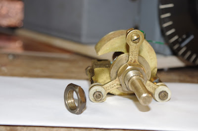
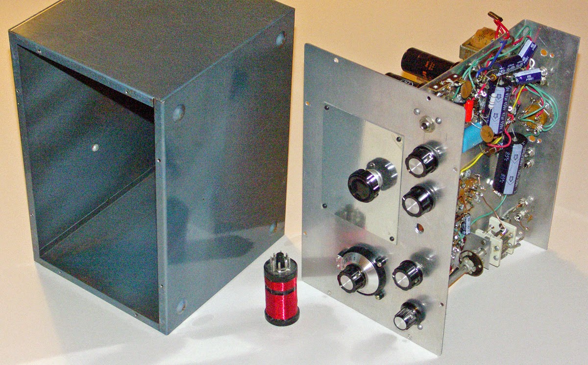
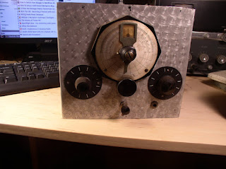
This beautiful old variable capacitor came out of a 1930’s British regen receiver that I picked up years ago at the Kempton Park rally near London. When I rebuilt that receiver, I found that the cap was thoroughly stuck. No amount of solvents could loosen it. I put it in the junk box and used a more modern cap in its place.
When planning for my current BIG VFO project (see yesterday’s post) I re-read Frank Harris’s chapter on VFOs. Frank recommended a non-linear cap — actually a cap that maintains a constant percentage change in capacitance as it goes through its tuning range. My old British cap seemed to fill the bill. Also, it appears to be brass or bronze which is said to have better temperature stability. So I pulled the Brit cap out of the junk box. It was still stuck, but as I tugged on it a bit, it suddenly loosened up. Wow! TRGHS.
When I tried to mount the capacitor in the QF-1 box, I discovered another problem: the nut for the main mounting screw was missing. And guess what: None of the nuts in my “big box of screws and nuts” (I know you guys all have one of these boxes) was the right size. Or, as Pete put it, all were of two sizes: a bit too big, or a bit too small.
Dex ZL2DEX informed me that the needed nut was likely an “Imperial Whitworth” (Don’t you love British names?). I started to think about how to get such an elusive part…. I thought about walking into Home Depot and asking them where they keep their Imperial Whitworths. This wouldn’t have been productive.
Then I started to wonder where the original nut went. It would have stood out in my junk box because it is brass-colored. I looked again in the junkbox. No luck. Then I realized that I might have used it to mount that replacement cap in my rebuild of the old British regen. I pulled that old beast (wooden chassis!) off the shelf. There it was, the needed brass nut. Cap and nut were reunited, problem solved.
It is kind of fun to include an old part like this in the new project.
Thanks Dex. And thanks again to Frank Harris for the great book.
1936 Shortwave Listener QSL card
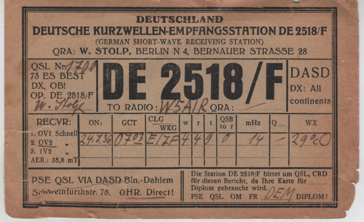
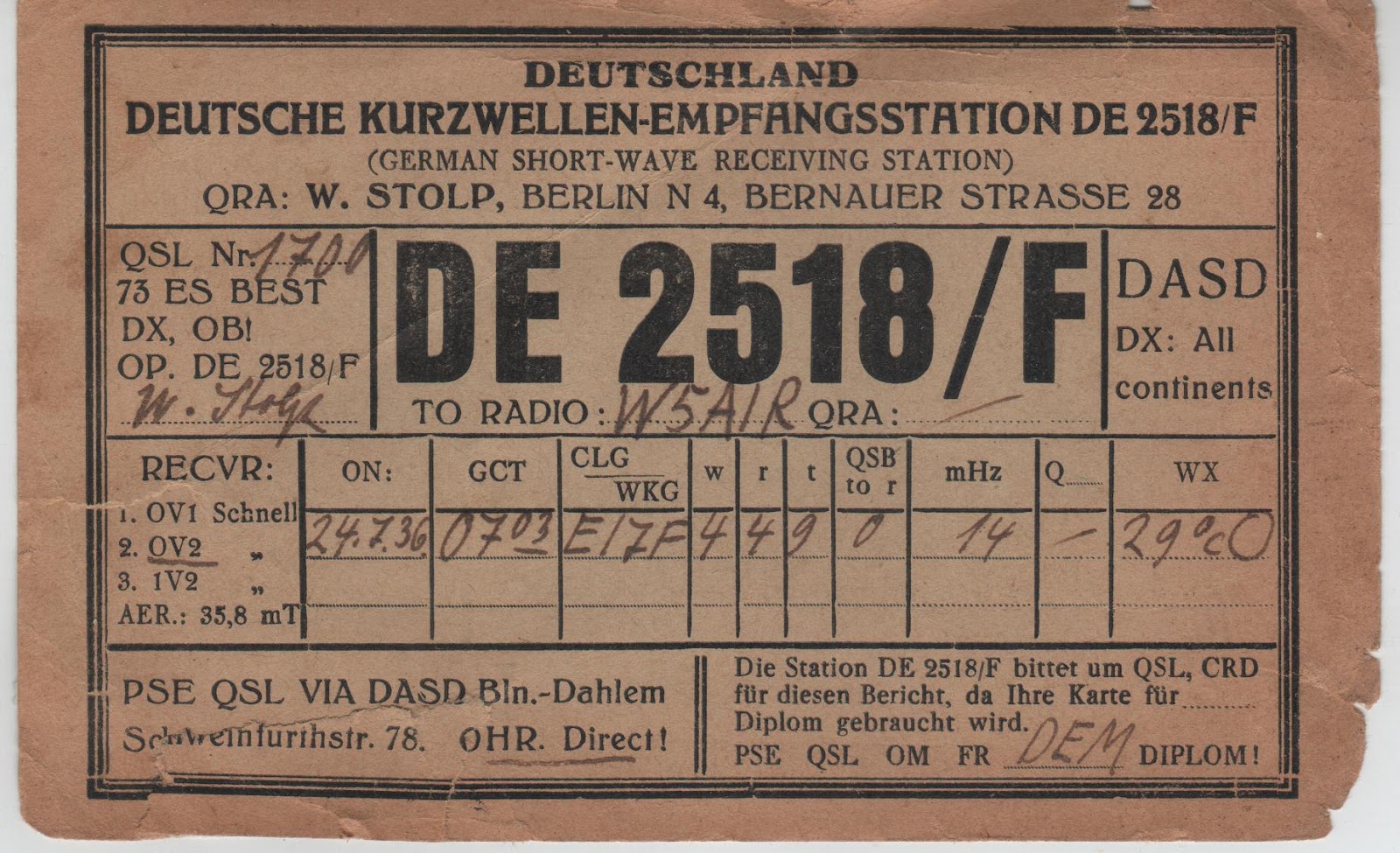
I found this today while rummaging around in the shack. It is starting to fall apart so I figured I better digitize it before it turns into dust.
July 24, 1936. 7 am in Central Germany. 29.0 degrees Centigrade. Clear skies? German Shortwave Receiving Station DE 2518/F monitored W5AIR’s contact with Irish station EI7F on 20 meter CW. The receiver was an OV2 Schnell tube (almost certainly a regen) fed by a 38.5 meter long antenna.
Conditions must have been pretty good — they were approaching the peak of sunspot cycle 17.
In 1954 W5AIR was assigned to Garold D. Sears. He was probably the operator.
German Thermatron Homebrew
Michael DF2OK has been melting solder in Germany. Above is a short video of the first sounds made by an AC-1 replica he built. Michael notes: “Yeah, I love these old style radios. You can see nearly everything. 🙂 BTW: All without Arduino and other black boxes and chips!”
FB Michael.
During the AC-1 build Michael struggled with a bad tube. His discovery and resolution of the problem is presented in this video (understandable even to those who don’t speak German):
Finally, here is a nice video of Michael’s 40 meter regen receiver. Anyone who has built or worked with a regen will understand perfectly this video. Watch Michael tune in stations while adjusting the regeneration. Note his demonstration of the lack of hand capacitance. FB Michael! Thanks!
AA7EE’s Beautiful Sproutie MK II
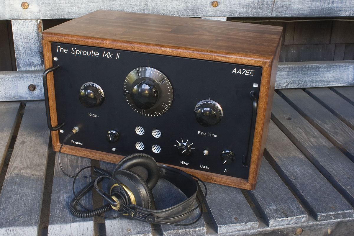
This is almost too much. Sensory overload is a real risk here. Go check out AA7EE’s amazingly beautiful regen receiver. On his site he has a masterpiece of a write up, along with schematics and build photos. I love the plug-in toroids. Great work Dave. Thanks for sharing this with the homebrew community.
Our book: “SolderSmoke — Global Adventures in Wireless Electronics” http://soldersmoke.com/book.htm Our coffee mugs, T-Shirts, bumper stickers: http://www.cafepress.com/SolderSmoke Our Book Store: http://astore.amazon.com/contracross-20
Kirk’s Herring Aid, Tuna Tin, and Regen Adventures

Hello Bill!
Just a quick hello from MN to tell you how much I have been enjoying your podcast. Although I have “plugged” your stuff in multiple magazine columns over the years, I’m a bit late getting into the listening game. My current contract job has me doing a lot of driving, however, so I now have several years’ worth of soldersmoke to enjoy.
Several of the most recent episodes have made it clear that we have covered some common ground in our amateur radio careers.
I was licensed in 1977 at age 15 — a year after I built my Tuna Tin 2 🙂 The transmitter was a smashing success. I used it with my Tempo One transceiver, or at the electronics repair shop at a local National Guard base (where my mom worked as a civilian administrator). I would ride my bike to Camp Ripley (only 8 miles or so), and the guys in the signal shop would let me use the shop’s Collins KWM-2 HF transceiver (and attached dipole). Other than my efforts, I don’t think the KWM-2 got much use…
I, too, tried to get the Herring Aid 5 to work, with no luck at all. Listening to your podcast was like being in a time machine of sorts 🙂 I wonder if I got the “sense” of the oscillator secondary messed up? I never did get that thing to make even a sound. I don’t have it any longer. The same goes for the TT2. They got “lost” when I stored a bunch of stuff at my dad’s place in-between moves, as did a home-brew 4-400A amplifier and a 6146B amplifier for my Ten-Tec Argonaut. Darn!
Don’t forget about the matching VFO — the Chopped Beef Slider (CB Slider), which was built into a chopped beef can, of course! I didn’t build one, but as I recall it was a diode-tuned 40-meter VFO for the TT2.
Your “regen rage” and its subsequent easing was also amusing. I have had a love-hate relationship with those buggers, too, although mine was mostly love. You referenced Dave Newkirk’s (now W9VES) 40-meter QST regen article in a podcast. I was fortunate enough to be a QST editor at the time Dave was in his “second residence.” That guy forgot more about receivers than I will ever know, and he helped me tremendously in official and unofficial capacities.
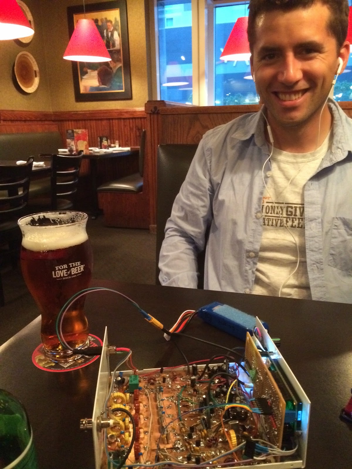
I have attached a photo (above) of a multiband regen that Dave helped me build (he designed and dispensed wisdom while I built the radio). He took a schematic from a 1930s ARRL Handbook and tweaked it a bit, helping me add a VR tube, “more modern” tubes and a few other goodies. Just to be difficult, I sampled the tank circuit with a tiny-value capacitor and a high-gain MMIC amplifier so I could drive a frequency counter, which displayed the receive frequency as long as the tank was oscillating. It was fun, but it was difficult to isolate the digital noise from the counter, so I only really turned on the counter as necessary, or to calibrate a dial, etc. The chassis used to be an Eico audio signal generator… In the photo the Jackson Brothers dial and bezel/tuning scale isn’t completely installed. After sitting in a box for 25 years, the regen still works but probably needs new tubes, as it’s rather deaf 🙂 Blasphemy aside, I’m moving on to solid-state regens…
I, too, just got a Rigol DSO. Wow, the “one-button” measurement is almost too easy.
I’m prepping my book, Stealth Amateur Radio, for release on the Kindle (and maybe other e-book formats), but it’s available now from my website, www.stealthamateur.com.
Keep up the good work, Bill.
I’ll be listening. 🙂
73,
–Kirk Kleinschmidt, NT0Z
Rochester, MN
Editor, 1990 ARRL Handbook
Technical Editor, Ham Radio for Dummies
QST Assistant Managing Editor, 1988-1994
Ham Radio Columnist since 1989 for:
Popular Communications
Monitoring Times and now,
The Spectrum Monitor (www.thespectrummonitor.com)
My book, “Stealth Amateur Radio,” is now available from
www.stealthamateur.com and on the Amazon Kindle (soon)
www.stealthamateur.com and on the Amazon Kindle (soon)
Our book: “SolderSmoke — Global Adventures in Wireless Electronics” http://soldersmoke.com/book.htm Our coffee mugs, T-Shirts, bumper stickers: http://www.cafepress.com/SolderSmoke Our Book Store: http://astore.amazon.com/contracross-20
Mama Mia! N2HTT’s Regen Receiver (Video)
I am fairly certain that Pete Juliano will take pride in N2HTT’s success on this project, and will attempt to attribute it, in part, to the Italian ancestry that they share. The Tarantella background music will definitely encourage that kind of thinking.
In presenting this nice video, we continue with our “rigs not yet in a box” theme. There is something especially nice about the sound of receivers that are not yet boxed up.
Mike has some great information on the construction of this receiver (and other projects) on his blog:
http://n2htt.net/
Bravo Michele!
Our book: “SolderSmoke — Global Adventures in Wireless Electronics” http://soldersmoke.com/book.htm Our coffee mugs, T-Shirts, bumper stickers: http://www.cafepress.com/SolderSmoke Our Book Store: http://astore.amazon.com/contracross-20
When Your Local Oscillator Could Sink Your Ship!
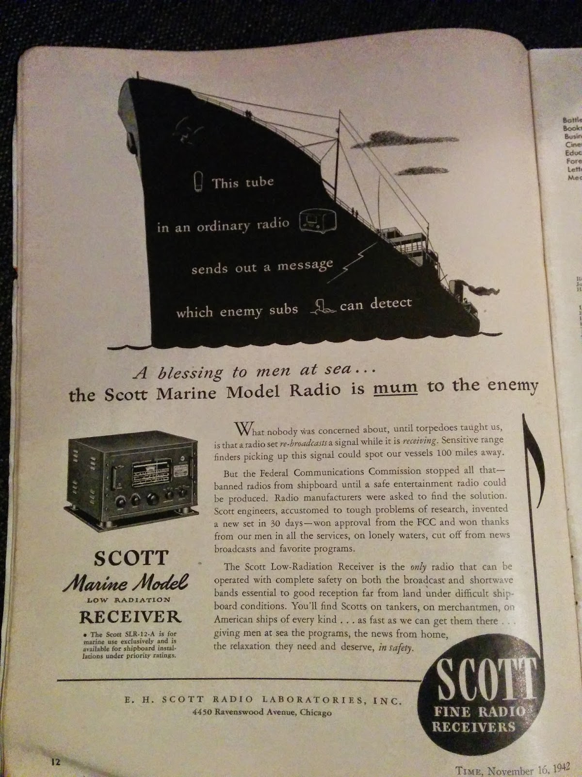
Thomas KK6AHT is the intrepid radio amateur from France who moved to California and successfully built a Minima as his first homebrew project. Yesterday we got additional evidence that Thomas definitely has THE KNACK. It seems that he has been looking through really old radio magazines (clearly a symptom). He sent us this add from 1942. Yikes! Imagine getting your ship sunk because your Local Oscillator is not quite local enough!
…………………
Hey!
I thought you would get a kick out of this 1942 ad. Sounds like those guys had a some good reasons to fight QRM … Who knew the important role played by the FCC during the war?
Now tell me: why were the receivers so noisy at the beginning of the war? What did they change? Happy new year to you both! May the gods of radio (and digital) bring you much fun on the air.
73, Thomas
…………………………
Good to hear from you Thomas. Long time no hear — I was beginning to fear that you had grown disillusioned with homebrewing and had switched to stamp collecting or something else less frustrating.
As for the ship radios, two things come to mind. Some of them may still have been using regens at the start of the war. If so, that was kind of suicidal — regens radiate! The detector moves in and out of oscillation (sometimes staying in oscillation) at the receive freq. The Germans were quite good at detecting and direction-finding these signals, on land and at sea. So the regens would have to go.
Superhets are not quite as bad, but they too can radiate. My Bitx spills out a bit of signal at 23 MHz (VFO) and at 5 MHz (BFO). Without adequate shielding, these sigs could also be detected and triangulated. Looks like the radio in the picture had lots of shielding.
We watched a French movie last night: The French Minister. A comedy about life in the French Foreign Ministry. It was kind of fun.
What are you working on? I am listening to 17 meters using an OLD superhet in which I have replaced the VFO with an Arduino/DDS generator. Works great but the display is making lots of noise.
73 Bill
…………………………….
Hi Thomas,
Well Thomas, I will dip my toe into some very deep water and attempt an answer for you which also is an important clue about QRP operations.
- Today we have many many signals co-existing in the radio spectrum. During the war there was much less radio garbage and the military lit up the ether with transmissions very sparingly. But that is on the transmit side. That said the local oscillators (much like you have with the Si-570 on your Minima) used in receivers also produce RF that unless is minimized in some fashion is passed right through to the antenna and can be detected. Regenerative receivers are especially prone to this. Yes some military equipment used regenerative receivers. In fact the famous Paraset had to be constantly moved so it would not be detected.
- This receiver generated RF into the antenna was addressed by companies like Scott by shielding everything. That receiver in the photo probably weighed about a 100 pounds or more. Much attention was paid to RF bypassing and grounding. The cheap table top radios were RF generators par excellence.
- There was another approach developed in WWII to solve that problem and forms the basis of what makes work that little device sitting in your pocket. The odd part it was invented by a famous movie star. Look up Heddy Lamar in wikipedia. She and a co-inventor came up with the concept of frequency hopping and spread spectrum technology. By jumping frequencies it would be hard to pinpoint a transmitting station. That concept forms the backbone of our cellphone system
- Now the QRP part – if the RF output from a receiver local oscillator (milliwatts) can be detected from afar – then it follows QRP works!
Have fun.
Pete
Our book: “SolderSmoke — Global Adventures in Wireless Electronics” http://soldersmoke.com/book.htm Our coffee mugs, T-Shirts, bumper stickers: http://www.cafepress.com/SolderSmoke Our Book Store: http://astore.amazon.com/contracross-20
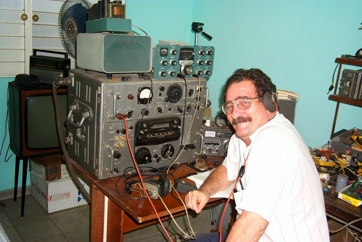
Who is this earnest young radio amateur?
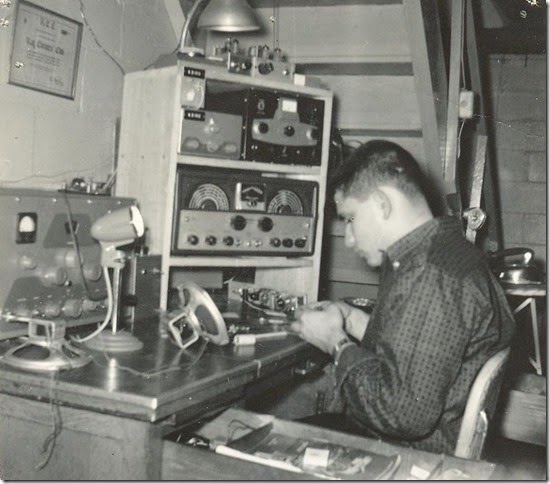
Name that ham! Here are his comments:
This is vintage early 1960’s and my call sign at that time was K3???. One of my favorite rigs was the Johnson Adventurer which I built and had a 6AG7 driving an 807 –50 watts input. On the top shelf near the lamp is the screen grid modulator for the Adventurer. I was in tall clover.
On the bottom opening is a 40M CW transceiver I built – it had a 6CX8 MOPA—about 5 watts. The RX was a two tube regen.
Our book: “SolderSmoke — Global Adventures in Wireless Electronics” http://soldersmoke.com/book.htm Our coffee mugs, T-Shirts, bumper stickers: http://www.cafepress.com/SolderSmoke Our Book Store: http://astore.amazon.com/contracross-20
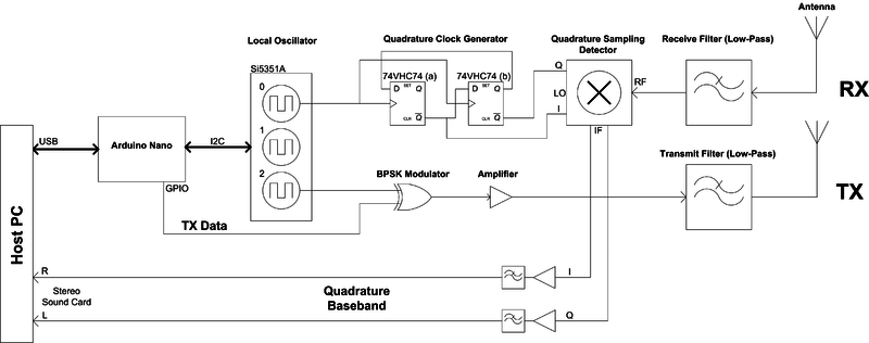
VK5FJ’s Open SDR Rig (Arduino and SI5351)
Morning OM’s,
I’ve amassed the parts for my 12v Regen Rx inspired by a projects from VK3YE and an audio amp, using a pair of 12AU7’s. I’ll publish more about that soon on my blog.
In the mean time, I’d like to thank you guys for inspiration on the si5351 VFO in use with various projects. After we found the first articles by NT7S, we discussed that there are a lot of possibilities.
I’ve just finished my build of an Arduino controlled SDR transceiver prototype using the Si5351A.
See attached images. Lots of collaboration with Mark VK5QI and David VK5DGR. More at; http://openradio.net.au/index.
This week I’m tinkering with the LPF for 20meters. Puts out a whopping 20mW.
Everything is on schedule for the presentation using this SDR at Linux.Conf.Au next year. Got some coding to do to add I&Q for the SDR side over the summer break.
72, Kim VK5FJ
Our book: “SolderSmoke — Global Adventures in Wireless Electronics” http://soldersmoke.com/book.htm Our coffee mugs, T-Shirts, bumper stickers: http://www.cafepress.com/SolderSmoke Our Book Store: http://astore.amazon.com/contracross-20
Radio China International Echo Mystery SOLVED!
For the past month or so I have been wondering about a strange echo that I’ve been hearing on the 31 meter transmissions of Radio China International. I first noticed it on my “Kings Speech” regen receiver. Then I heard it again on my “Off the Shelf” regen.
For a while I thought that what I was hearing was a propagation effect: Perhaps the very strong RCI relay station in Quivican,Cuba was sending north a signal so strong that it was travelling around the earth along the grey line and coming back to me about .133 seconds after the original reception.
This sounded plausible (and it does happen sometimes). But there were reasons for skepticism: Why wasn’t anyone else hearing this? Why wasn’t the effect showing up on signals from Radio Havana Cuba?
Pete Juliano had suggested that perhaps I was getting signals from TWO different RCI transmitters. I had quickly checked the RCI schedule and didn’t see them transmitting on the same frequency at the same time from multiple transmitters, so I kind of put that idea aside. Hey, the round-the-world idea was just more appealing!
But then I remembered something strange about the echo: It seemed to disappear when I tuned close to the center frequency of the RCI signal, but then appeared when I tuned off to one side. Hmm…. That was an important clue.
I’ve long been wary of regen receivers and for a while suspected that I was dealing with some weird regen effect. Regen and Echo seem to go together, right? Well, as it turns out, no. But I was right about this being an effect of the nature of my receiver…
Last night I was listening to RCI English service at around 0030 UTC on 9570 kHz. Nice clear signal. No echo.
At 0100 UTC the program changed, and the echo started. A very strong echo.
I went to the RCI schedule. Here I found the answer:
At 0030 they were transmitting from their relay station in Cerrik, Albania on 9570 kHz.
At 0010 they switched programs, frequencies and transmitters. At 0100 Cerrik shut down, but the Quivican, Cuba relay came on on 9580 kHz. At the same time the RCI transmitter in Kasi Sabagh in far-off exotic Western China, in Xinjiang, fired up on 9535 kHz. Both transmitters were carrying the RCI English service.
You see, my little regens are not very selective, and the RCI transmissions are quite strong. So if I have my receiver tuned to around 9560 kHz, I’ll be hearing BOTH the signal from Cuba AND the signal from Xinjiang. That would explain the echo.
To try to confirm this, last night I fired up my old Hammarlund HQ-100 receiver to see if I could discern the two different signals. I could. And the echo appeared when I tuned BETWEEN the two. You can hear this in the video above.
There is one remaining question here: Is the echo caused by the RADIO path difference between the two transmitters? Or are we just seeing the effect of the programming being transmitted at slightly different times, perhaps with this delay caused by INTERNET latency? Anyone know how RCI gets its signals from its Beijing studio to its distant transmitters? I calculate that the path difference is about 10,000 km. With c at 300,000 km/second, that would yield an echo of only about .03 seconds. The echo we are hearing sounds longer than that, so I suspect we are hearing a difference in studio-transmitter transmission time. What say the SWL RF gurus?
BTW: I think the same phenomenon may explain the echo on Brother Stair’s “Overcomer” signal. I see that starting at 2200 UTC he is on BOTH 7570 kHz and 7730 kHz from RMI transmitters in Florida. Perhaps they are not synched up.
I think this is all very cool. Think about it: Here I am, sitting in Virginia in 2014, listening to the Albanian, Cuban, and Xinjiang relay stations of Radio China International on a receiver first built by some guy in England during the 1930s. And I’m trying to figure out if the echo I hear is caused by the limits imposed by the speed of light and the size of the earth, or by the time it takes packets to move through sub-oceanic fiber optic cables.
Our book: “SolderSmoke — Global Adventures in Wireless Electronics” http://soldersmoke.com/book.htm Our coffee mugs, T-Shirts, bumper stickers: http://www.cafepress.com/SolderSmoke Our Book Store: http://astore.amazon.com/contracross-20
Regen Receivers in Cuba

Hola amigo Bill:
I was able to pick up the podcast with excellent audio quality.
It is quite true that regenerative receivers are very much in use
even today… for example many if not all of the automobile RF
keys opening and closing the cars doors rely on a superregenerative
receiver circuit !!!
The radio that you copied at the blog works very well indeed
but it would be good idea to include a 5 kilo ohms volume
control…. Very easy to do indeed.
But let me tell you that my favorite regenerative receivers are
the classic ones, using vacuum tubes, and operating them
at voltages not higher than 50 volts… As a matter of fact many
tubes work very well at the 24 volts DC voltage level.
Using the classic Hartley circuit , there is no need for a hard to
find throttle capacitor required by the Armstrong circuit, because
the regeneration control works very well by using a potentiometer
to change the screen grid voltage of the detector.
I agree that using an RF stage ahead of the detector is always
a very good idea…. In my tubes regenerative I use a triode connected
6AK5 clone…. as a grounded grid stage….another 6AK5 clone ( the
6ZHE1P Russian tube ) is the detector and I use another 6AK5 clone
as the first audio amplifier then feeding an audio output pentode
all provided from a very simple basic 70 volts DC power supply.
BTW, using regulated DC on the filaments of the detector stage,
although a luxury by my standards is very helpful to reduce
hum …. 7805 regulator recycled from a bad motherboard, with
one 1N4007 from broken Compact Fluorescent Lightbulb inserted
in series with the regulator ground pin, produces a nice 5.7 volts
regulated DC that with a brand new tube is more than enough… with old
6ZHE1P recycled from Russian TV sets, you add another 1N4007 to obtain
6.4 volts regulated DC….
As said in the podcast, it is very important to do a very good
mechanical engineering job, place the main and bandspread tuning capacitors
away from the front panel, use isolated shafts between the capacitors
and the dial mechanism and make the front panel of a a thick steel
plate if possible.
There is a Dutch Cascode Regenerative radio that several Cuban radio
amateurs have built… it was designed with the amateur bands in mind so
the information about the tuning coils and capacitors lets you
obtain a very excellent bandspread on the ham bands.
I can send you that circuit that uses very common 12AT7-ECC81
and Russian equivalent double triodes.
Keep up the good work amigo and always tell us when the next
podcast is available. BTW it lasted for almost an hour !!!
73 and DX
Your amigo en La Habana, Cuba
Arnie Coro
CO2KK
Host of Dxers Unlimited radio hobby program
Radio Havana Cuba
Our book: “SolderSmoke — Global Adventures in Wireless Electronics” http://soldersmoke.com/book.htm Our coffee mugs, T-Shirts, bumper stickers: http://www.cafepress.com/SolderSmoke Our Book Store: http://astore.amazon.com/contracross-20
“Off the Shelf” Regenerative Receiver
I call it the “Off the Shelf” Regen because the base on which it is built is scrap lumber from a recent shelf building project. Also, all the parts came out of the junk box.
6-10 MHz, AM, CW, SSB, Data. 4 transistors, no chips.
Our book: “SolderSmoke — Global Adventures in Wireless Electronics” http://soldersmoke.com/book.htm Our coffee mugs, T-Shirts, bumper stickers: http://www.cafepress.com/SolderSmoke Our Book Store: http://astore.amazon.com/contracross-20
Sometimes the Receivers Seem to Almost Self-Assemble

I’ve been building shelves for my wife. So I end up with all these nice pieces of pine, just the right size for the base of a breadboard receiver and a very sturdy cabinet to surround it. Then I find in the junk box two nice variable caps and this old pill bottle coil (with tickler!) that I wound in 1998; I figure they will resonate from around 5 – 15 MHz. Then Jeff Murray, K1NSS does that poster about Dave Richards, AA7EE (scroll down) in which he mentions the virtues of a National Velvet Vernier reduction drive — I have one of those too. And then there is the copper-clad board (from AL7RV/W8NSA) that would be perfect for the front panel. You see where this is going, right? My friends, I am once again on the road to shortwave regeneration. It will have an Armstrong detector with throttle cap.
Our book: “SolderSmoke — Global Adventures in Wireless Electronics” http://soldersmoke.com/book.htm Our coffee mugs, T-Shirts, bumper stickers: http://www.cafepress.com/SolderSmoke Our Book Store: http://astore.amazon.com/contracross-20
Youth, Short Waves, and the Invigorating Properties of Regen Receivers
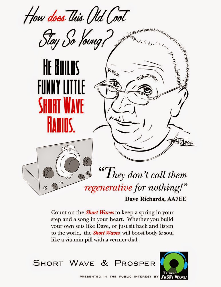
Oh man, when I saw this I just had to put it on the blog. The artist is Jeff Murray, K1NSS, the genius behind Dashtoons. Dave Richards AA7EE is, well, the OC!
So not only have we learned that regen receivers are NOT demonic, we now see that they have health enhancing properties! Like all that antioxidant stuff! This is great. I’m feeling younger already.
Regen on my friends!
Our book: “SolderSmoke — Global Adventures in Wireless Electronics” http://soldersmoke.com/book.htm Our coffee mugs, T-Shirts, bumper stickers: http://www.cafepress.com/SolderSmoke Our Book Store: http://astore.amazon.com/contracross-20
Cutting Edge Regens! No, really.
Bill –
Thanks so much for featuring The Sproutie on your blog. I heard through my friend Jason NT7S on Twitter that you had built a regen and we both did a double-take. Bill from Soldersmoke building a regen – and enjoying the experience? I was frantically pinching myself, as it just didn’t seem likely, given your past bad karma with them but there it was – a lovely old set with that great brushed aluminum finish with the swirls on the front panel – and being worked on by Bill N2CQR. Wonderful! I have been meaning to either e-mail you, or comment, perhaps below the post in which you featured the letter from Todd VE7BPO. I discovered recently that although we think of regens as being an established, and now stagnant technology, there are still people doing cutting edge research on them. Some of the discussion was in the Yahoo regenrx Group, and much of the research is being done by a fellow from NJ with the username vladn. Concerning the phenomenon that we notice with our regens that, as we get close to the threshold of oscillation, the bandwidth narrows, and then as we advance into oscillation (as we do to receive SSB and CW), the bandwidth broadens out somewhat, I am going to quote verbatim a comment that was left on my blog by user qrp.gaijin,
This phenomenon has been deeply analyzed and explained (by user “vladn”) here:http://theradioboard.com/rb/viewtopic.php?f=1&t=4680&start=0 . It is, in fact, possible to completely eliminate this phenomenon; bandwidth can be controlled independently of oscillation amplitude (to choose a desired amount of selectivity), and oscillation amplitude can be controlled independently of bandwidth (to control how easy it is for the regen to lock on to the incoming signal: we want a low oscillation amplitude and easy locking for synchronous AM reception, whereas we want a high oscillation amplitude and no locking behavior when listening to SSB). Eliminating this phenomenon, i.e., separating control of bandwidth and oscillation amplitude, can be done by using an explicit amplitude limiter (i.e. a separate transistor/tube stage as part of the oscillator’s explicit amplitude stabilization control loop) that exhibits scale-independent gain compression. In other words, regardless of the oscillation amplitude, if the oscillator’s gain compression (amplitude limiting) behavior is scale-independent, then the final result of the repeated selective amplification (that defines the final regenerated Q and bandwidth) will be the same, regardless of the oscillation amplitude. See this video (by vladn) for a demonstration of independent control of oscillation amplitude and bandwidth: http://www.youtube.com/watch?v=UyqD99WGlss .
The fellow in NJ whose username is vladn has built a regen to test the above theory, and it works! You can see it in the video that is linked in the above quote. vladn has done other equally cutting edge research into regens, but I wanted to let you know that these little receivers are still being developed and improved by a few intrepid experimenters. Howard Armstrong would be so proud!
Best of luck building your regen Steve. With Bill Meara now a regen fan, the radio Gods are on your side!
73,
Dave
AA7EE
Best of luck building your regen Steve. With Bill Meara now a regen fan, the radio Gods are on your side!
73,
Dave
AA7EE
****************
Hi Bill and Dave,
The Soldersmoke blog post about the Sproutie super-regen radio by Dave got my soldering iron warm without even turning it on! That National N Velvet Vernier dial really got my homebrew and radio nostalgia juices flowing with that beautiful nickel plating and the big shiny Bakelite knob. Plus the use of modern semiconductors along with an Octal socket for the plug-in coils was almost too much to bare.
I immediately bought the National dial and the two variable caps on eBay and from the link Dave suggested in his post for the dial. That custom chassis company, while in Nova Scotia, is quite close to me here in Maine, and I just might have to visit them to talk about the details of my proposed chassis.
The obvious next step is a real PCB, but Dave’s beautiful technique using the ME squares and pads is hard to argue with. Those solder-friendly squares and pads are local to me too from good ol’ Rex Harper.
Bill, many thanks for your post and link. Dave, thanks for the great design and implementation, as well as the amazing details and photos on your blog. I think I see a HB super regen project in my immediate future. The parts are piling up! Gary sold out of the N dials almost immediately.
73
Steve Silverman KB3SII … .. ..
**************
I’m really glad that Steve wrote in because his e-mail reminded me that I need to thank him again for the multiband dipole that he sent me a couple of years ago. For a number of reasons I couldn’t really use it in its original configuration, but the wire has been used in almost all my recent antenna projects, including the magnificent Moxon. The black insulation was just what I needed for that essential stealth effect. Thanks Steve.
Our book: “SolderSmoke — Global Adventures in Wireless Electronics” http://soldersmoke.com/book.htm Our coffee mugs, T-Shirts, bumper stickers: http://www.cafepress.com/SolderSmoke Our Book Store: http://astore.amazon.com/contracross-20
Some Inspiration on Receiver Building

As a result of all the recent toob talk with Pete Juliano I’ve been going to work with old copies of Electric Radio in my backpack. Yesterday, somewhere in the tunnel under the Potomac River, I read these inspiring words from master receiver builder Bob Dennison, W2HBE (SK):
“Part of the fun in the radio building hobby is tearing up a set after a short period of use so its parts can be used again in a bigger and better set. Another order is sent to Allied Radio for an audio transformer, an RF choke, a vernier dial and some of those exquisitely beautiful Hammarlund variable condensers. Oh what a joy it is! You just haven’t lived until you’ve built a whole series of progressively more exotic receivers. Give it a try!” (ER, March 1993)
Our book: “SolderSmoke — Global Adventures in Wireless Electronics” http://soldersmoke.com/book.htm Our coffee mugs, T-Shirts, bumper stickers: http://www.cafepress.com/SolderSmoke Our Book Store: http://astore.amazon.com/contracross-20
VE7BPO on the Trivialization of Regenerative Receivers

Todd Gale, VE7BPO, is a true HOMEBREW HERO. His QRP POPS website has been a source of inspiration and information for many years. Todd wrote in yesterday on the trivialization of regens and what we should do about it. Thanks Todd!
Dear Bill:
With due respect, I challenge the statement that many feel regenerative receivers are trivial. I submit that most of us know that regens offer good sensitivity + selectivity despite their few parts, however, we ourselves, may trivialize the regen by our lack of literature reviews, experiments, imagination and attempts to improve its downfalls.
Where are the bench experiments and inspired discussion that address issues like designing circuitry to reduce overload and blocking while still maintaining high sensitivity when needed, hum + noise reduction, AF filtration, or ways to reduce RF pollution into the RF lab environment?
Much work on regens and of course, its amazing sister, the super-regen dots the literature. People did make many experiments to explore topics like vario-couplers, litz wire coils with low applied power regen detectors, sensitivity analysis, noise analysis and frequency domain calculations.
We now tend to see or present über basic regenerative receivers complete with LM386. Yet, still we authors somehow feel people might not respect the regen? Really?
Another factor: as my regen grows in complexity, shouldn’t I just make a zero IF radio (now just as simple with a dongle or two I/Q mixers going into sound card), or perhaps make a simple superhet with some computer crystals for the IF filter?
Regenerative receivers remain cool. Perhaps putting both hands on the controls plus the antenna coupling are just part of the regen experience and like a standard versus automatic transmission, offers more visceral listener engagement?
No doubt, nostalgia and love for simplicity color the regen experience. Now is the time to make a regen — If you listen carefully — inside many big cities the crashing sound you hear is yet another SW tower coming down.
Hats off to you Bill and also to Dave, AA7EE for his stellar blog presentation.
Todd, VE7BPO
Our book: “SolderSmoke — Global Adventures in Wireless Electronics” http://soldersmoke.com/book.htm Our coffee mugs, T-Shirts, bumper stickers: http://www.cafepress.com/SolderSmoke Our Book Store: http://astore.amazon.com/contracross-20
Regen Madness
Dave, AA7EE, has a really nice blog article about his experiences with regen receivers. He writes about a regen kit he built as a kid (pictured above) and goes on to describe in beautiful detail a regen he built recently using a combination of old tech and new tech:
http://aa7ee.wordpress.com/2014/08/21/the-sproutie-a-general-coverage-regen-receiver-with-plug-in-coils/
I agree with Dave when he notes that regens are unfairly thought of as mere novelties. My old “King’s Speech” regen (below) is a very useful shortwave listening receiver and could easily be used for 40 meter CW contacts. It is even stable enough for SSB.
Our book: “SolderSmoke — Global Adventures in Wireless Electronics” http://soldersmoke.com/book.htm Our coffee mugs, T-Shirts, bumper stickers: http://www.cafepress.com/SolderSmoke Our Book Store: http://astore.amazon.com/contracross-20