AA1TJ — On the Air with a Tuning Fork Transmitter using the 2,212th Harmonic and Olive Oil Cooling

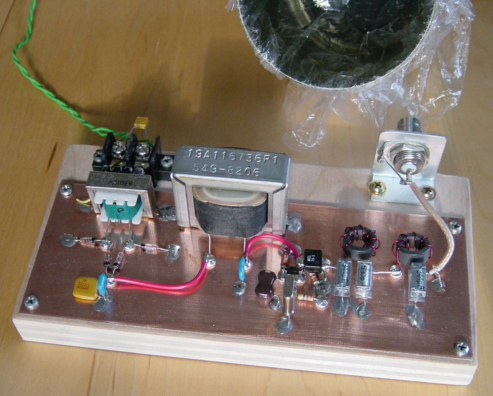
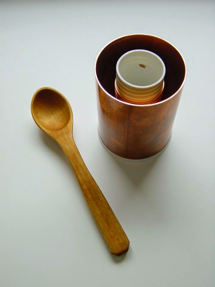
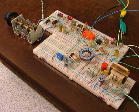
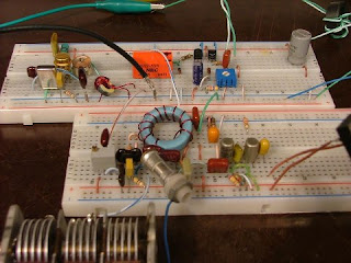
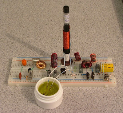
The saturable magnetic frequency septupler. The tiny computer memory core is submerged in olive oil (Italian…naturalmente).

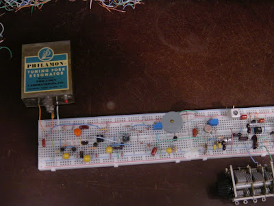
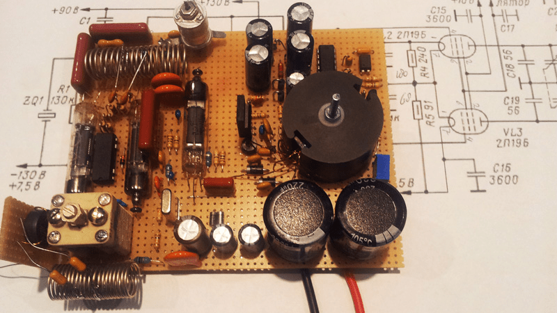
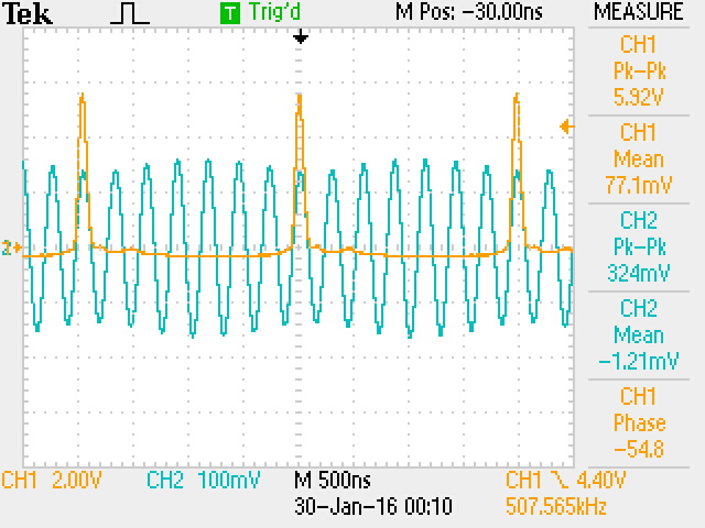
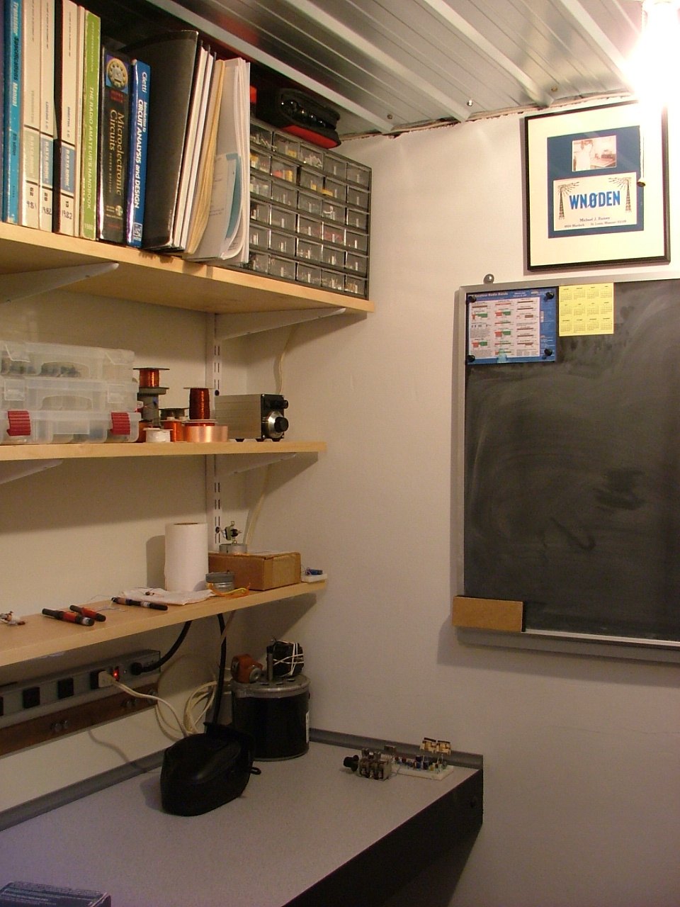
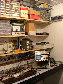
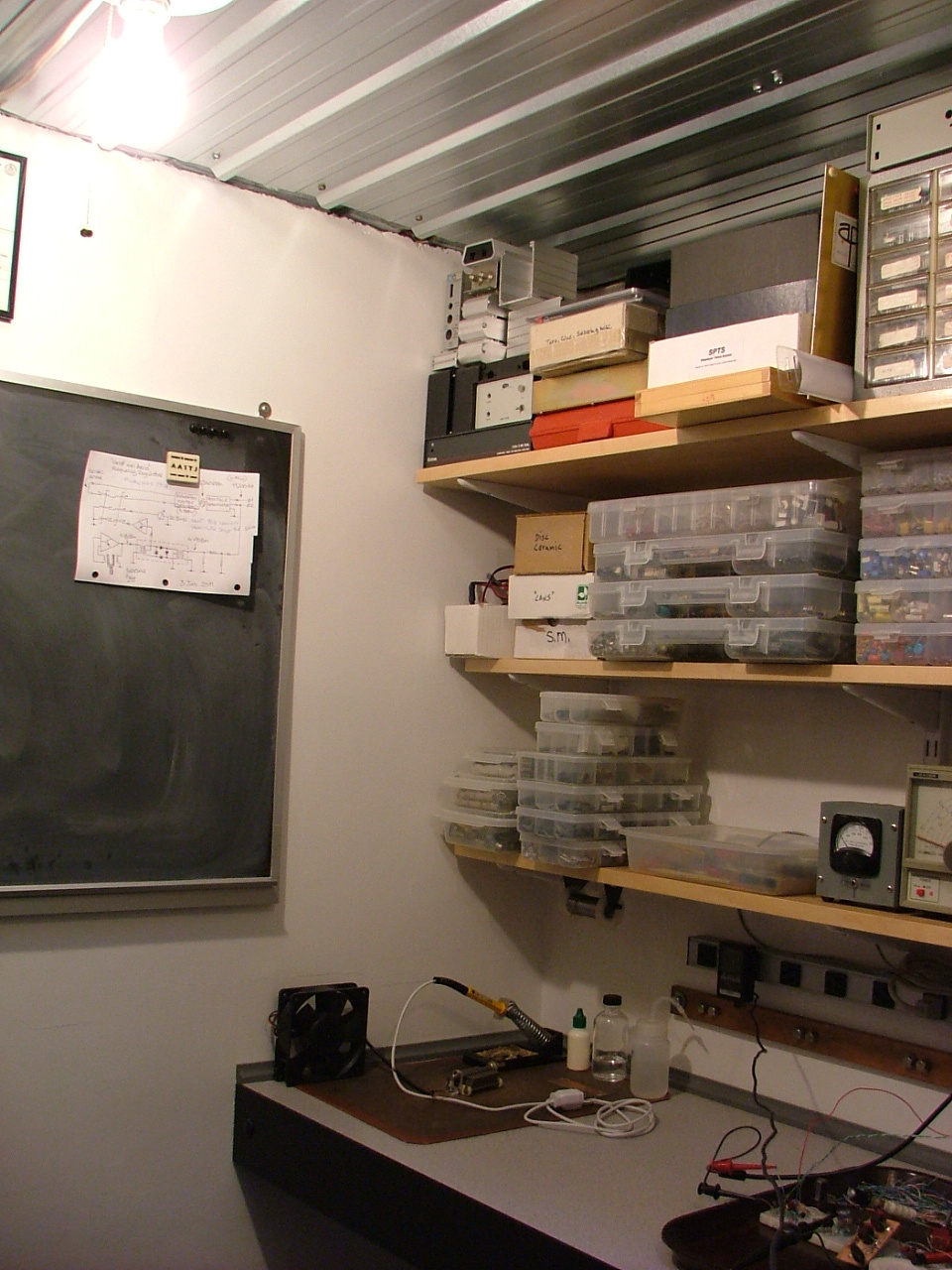
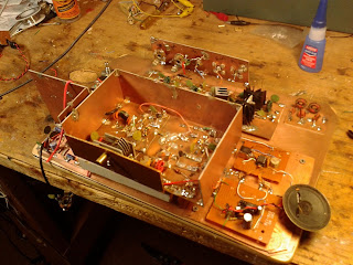
Not a very good picture, but here’s the 1600Hz tuning-fork, fork oscillator, SRD pulse generator, PLL S/H phase-detector (diode gate), differential amplifier D.C. amplifier, and part of the 500kHz VCO.


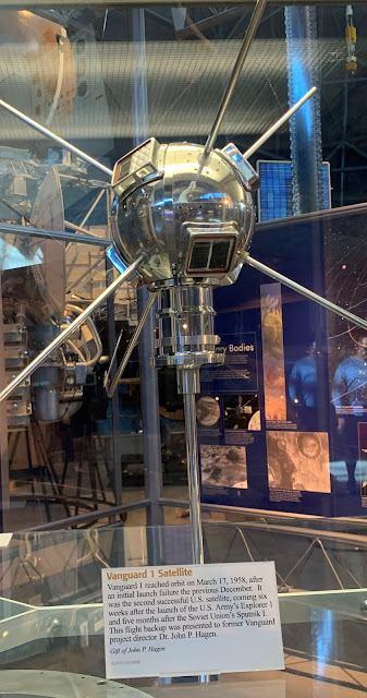
The Wizard (AA1TJ) reports from the Hobbit Hole:

I was pleased to have made the first contact with my tuning-fork transmitter this evening. My contact, N1QLL, runs a pretty B&B on the Maine seacoast, midway between Bar Harbor and Cutler. Jerry was operating a solar-powered QRP station. I found a follow-up email from him when I came up to the house for dinner. He’s asking for a better explanation of my set-up. I can’t wait to tell him about the passive frequency septupler made from an East German computer memory core, heat-sinked in a thimble of olive oil.

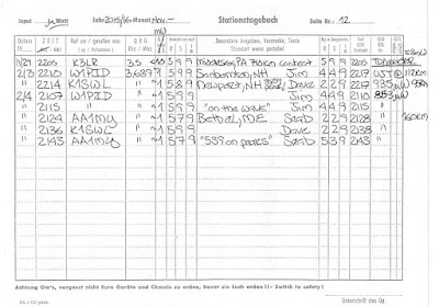
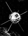
My signal was also logged by a number of automated “Reverse Beacon Network” receivers (image attached) located in Ohio, North and South Carolina, Virginia and Pennsylvania…not bad for 90mW on 80m. Please note that my operating frequencies, 3,528.0 and 3,539.2kHz, are the 2,205 and 2,212th harmonics, respectively, of my 1,600Hz tuning-fork frequency reference.
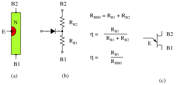
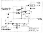
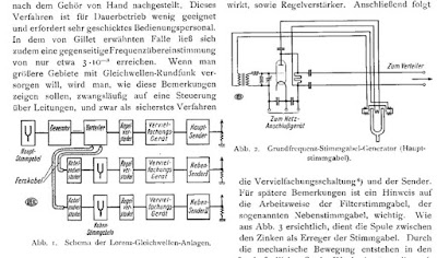
FYI: the third attached image illustrates the block-diagram and tuning-fork reference oscillator circuitry for three common-wavelength AM broadcast transmitters operating in Berlin, Stettin and Magdeburg, Germany from 1928 through the mid 30’s. A central 2,000Hz tuning-fork generated reference carrier was transmitted by landline to transmitters in the aforementioned cities whereupon the 529th harmonic was generated, amplified and broadcast at 1,058kHz. The equipment was designed by the Berlin-based firm, C. Lorenz A.G.. The fourth image details Lorenz’ technique of frequency multiplication via saturable magnetic iron-core inductors. My septupler operates in an identical fashion.
A very pleasant day…

Mike points out that this is a work in progress. He hopes to cross the pond (the Atlantic!) soon. Here is a update from Mike:

A nasty cold has delayed work on the 20 meter implementation, although some of the time I’ve spent crashed on the sofa was put to use redesigning the loop filter network. I think yesterday might have been my “hump” day so I’m looking forward to getting in some quality bench-time over the weekend.

By the way, my PLL-based transmitter frequency stabilizing circuit has much in common with a garden-variety frequency-synthesizer. Obviously, the tuning-fork frequency reference is the main point of departure. My sampling phase detector, for example, was old hat by the mid-1960’s. Nevertheless, this has been a fun project.

Sputnik Replica Transmitter, an “Error” in the Sputnik Schematic, and Why 20.005 MHz?

Mark K6HX pointed me to very interesting Hackaday article on Frank PA3CNO’s Sputnik transmitter replica. As blog readers will recall, we went through a period of Sputnik-mania a few years ago: http://soldersmoke.blogspot.com/search?q=sputnik Chief Designer Comrade Mikhail Rainey AA1TJ sent me some of the Russian tubes (like those pictured above).

The Hackaday article pointed to our post reporting that Oleg RV3GM had found the schematic:
http://soldersmoke.blogspot.com/2013/04/sputnik-schematic-found.html Stefan reports that PA3CNO found “an error” in the original Soviet schematic:
http://www.radio.cc/post/Franks-power-supply-for-sputnik A mistake you say? HAH, I say! Hah! This must have been part of a sinister commie plot to prevent the capitalist imperialists from ever being able to reproduce the glorious transmitter of the Soviet people. They almost succeeded.

Just kidding.

In the course of looking through our old Sputnik posts, I came across a question I posted:

I have a question: OK so the crafty Soviets picked 20.005 MHz for some good reasons: Being so close to the WWV freq, it would be easy for hams and SWLs to find it with precision. In the November/December 2007 issue of “Break In” (from NZ — thanks Jonathan-san!) ZL3DW notes that this frequency selection would allow a receiver set to exactly 20 MHz to “produce an audio tone plus or minus the Doppler shift without ever going through zero beat.” But zero beat with what? Most of the receivers out there would not have had BFOs, right? So the Soviets wouldn’t have been using ordinary CW, right? Were they using AM, with the beeps produced by an audio oscillator modulating the carrier?

Was their diabolical plan to use WWV as the BFO for those using ordinary AM SW receivers? If so, a 5 kHz separation from WWV seems to be too much right? Especially when the Doppler shift on approach would push the frequency up a bit. Maybe they just chose this freq to make it easy for listeners to find — just a bit above WWV. Comrade Rainey surmised that they were keying the PA stage — the oscillator “backwave” was at times audible on the ground.

What do you think Comrades?
DSW and 73.

“QSO Today” Podcast Interview with Michael Rainey AA1TJ

Picture

Eric 4Z1UG has a really great interview with Michael AA1TJ:

I listened to it as I aligned my HQ-100 receiver and worked on a digital frequency readout for the old receiver. The interview was the perfect accompaniment for such a project. Inspirational stuff. Lots of great info on QRPp and homebrewing. Mike talks about some of his more famous rigs including the voice-powered New England Code Talker (pictured above).

I loved the story of Michael carting his DX-100 home in a wagon. And I really sympathized when he described the harsh reaction of the phone operator to his early efforts at voice modulation.

Strongly recommended! You won’t be disappointed. Great interview. Thanks to Eric and Mike.


Michael’s Log: AA1TJ Has FIVE Contacts with the Unijunction Transistor at 1-2 milliwatts

Michael writes:

Dear Friends, The UJT transmitter circuit was improved considerably today. The power output has increased to 1.48mW and the start-up “whoosh” is now far less objectionable. It’s currently running in beacon-mode at 3687.8kHz. I’ll resume “CQing” as soon as I’ve returned from an hour’s walk in the woods. I hoping to work K1QO among others. 73, Mike

Added five QSOs today. Seabury/AA1MY is in Maine…exactly 100 miles from my doorstep. It’s wild to think that we made a one-hundred mile radio contact on a unijunction.

A Probable First: First Ever Radio Contact Using Unijunction Transistor as the Transmitter

AA1TJ writes:

I spent most of a week working to raise the RF output power from my unijunction transmitter to nearly 1mW. I was rewarded this evening with two contacts.

Jim/W1PID exchanged (599/449) signal reports with me from Sanbornton, NH (112km) at 2210z!

Dave/K1SWL did the same (589/229) from Newport, NH (95km) some four minutes later!

I should think these were the first-ever radio contacts made using a unijunction transistor as the transmitter.

FYI: my receiver was comprised of a single 1N34a germanium diode mixer followed by a single 2N35 germanium transistor audio amplifier. Great signals on this end.

Wikipedia on Unijunction Transistors: https://en.wikipedia.org/wiki/Unijunction_transistor

RESISTANCE IS FUTILE! Diode Tunnels in Germany and Vermont

Peter DL3PB’s Zinc Negative Resistance Transceiver

Michael Rainey AA1TJ’s work with tunnel diode rigs has provided much grist for the SolderSmoke mill over the years, as has the tunneling of Peter DL3PB:
http://soldersmoke.blogspot.com/search?q=tunnel+diodes

They are back at it!

Michael updates Peter (and us!) us on his efforts of this week:

Grüss Peter!

A broadband measurement of my output power (using an AD8307 log-amp power meter) indicates 139uW. Spurious frequency energy accounts for 2uW, leaving 137uW at 3.552MHz. I believe this is roughly the output power produced by your ZnO transmitter?
This morning I’ll attempt to increase the unijunction (UJT) 80m RF output power by inserting a pair of back-to-back standard-recovery power supply rectifiers (1N5401-ish) at the UJT base-2 to ground node. Thus far I have relied exclusively on internal UJT nonlinearity for the generation of harmonic energy. I’ve reason to believe the minority carrier charge-storage capability (normally a defect, but hopefully a virtue here!) of these rectifiers will efficiently produce a bipolar pulse-pair every 1/500kHz seconds resulting in an odd-order comb-spectrum. At least that’s the plan…we’ll see how it works out 😉
Peter, I never heard the results of your ZnO DXpedition? Any luck OM?

Okay, I’m off to the Hobbit-Hole. My heartfelt thanks to you all for your shared interest in this cock-eyed project.

73,
Mike, AA1TJ
Peter, DL3PB, in Germany respond with amazing news of his own. Peter is homebrewing his own tunnel diodes, using Zinc Negative Resistance Oscillators. No store-bought appliances for him!
At this point you really have to visit the pages of Nyle K7NS
and
Nyle tells of building a little microwatt transmitter, and, once the snow melted, climbing a hill 5 miles from town to see if he could hear it. This reminded me of young Marconi’s early efforts in Bologna.
Peter writes:
Hi Folks,

Mike, your plan on how to increase output-power sounds reasonable – yes, a few dB could really help, to make reception a bit steadier and thus allow a QSO.

Well, I thought we had already talked about the ZnO TRX attempt, but obviously we didn’t. The reason is dead simple – It didn’t work.

[ The ZnO TRX is a minimalist 80m band transceiver with a homemade tunnel-detector-diode as the only active device – based on Nyle’s K7NS experimentshttp://sparkbangbuzz.com/zinc-osc-2/zinc-osc3.htm – please find attached an early schematic ]

Three days in a row after Xmas I tried for several hours each, I had announced the activity on QRPSPOTS and the German QRP Forum. Thus several guys
within the right distance were really trying hard to copy. I used different temporary antennas, mostly verticals, but also a sloper dipole – nada, niente , nothing.
One or two OMs reported weak CW signals on the scheduled QRG, but too deep in the noise, to even make out, whether it was me or someone else.

Yes, power is more or less comparable, actually it’s 0.5mW +/-3dB depending on the day’s form of the homemade tunnel-detector, but I guess all my antennas are
some dB behind a full-size dipole, so at the end it’s pretty much the same.

Folks were very cooperative during the test itself, but after it was clear, that it had not worked, the usual trolls showed up to explain, why that never could have worked…
I plan another test within the coming week e.g. during the PA-contest next weekend ( I’m only 30km from the dutch border ) with a base loaded 15m vertical –
be assured, you’re the first to hear about any success in terms of QSO or just being heard anywhere.

What would we go for, if everything works as expected and/or right from the beginning – or as Jim said it : What fun…

73!

Peter/DL3PB


Finally, Alan Wolke provides a very illuminating (as always) explanation of tunnel diodes):


AA1TJ’s 150 Microwatts Heard at 112 Kilometers — “To Boldly Go Where no Unijunction Has Gone Before.”

AA1TJ reports:

Breaking news from W1PID… “Mike! I just copied the beacon. I got ‘VVV de AA1TJ 150 uw’ and it faded out. 2146Z on 3551.95MHz” That’s it! Jim copied a message produced by a lowly unijunction at a distance of 112km. How’s that for cool! In a nutshell… the unijunction runs as an R-C relaxation oscillator at ~500kHz. A quartz crystal at the emitter frequency-locks the sawtooth waveform to 507kHz. The 7th harmonic is admitted to the antenna via a bandpass filter. The RF output to DC input conversion efficiency is all of 0.1%. Heat-sink? Check! Mission statement:
“…to boldly go where no unijunction has gone before.”
Cheers,
Mike, AA1TJ


I think the really cool thing is that EM waves are once again flying out of the Vermont Hobbit Hole, propelled into space by the poet laureate of QRP.

Modulated Michigan Mighty Mite?


This suggestion from across the pond is a bit “out there.” In fact, for me it brought to mind the famous line from the Noel Coward song about who goes out in the mid-day sun… This does seem like an endeavor for our stoic British cousins. You’ll need a very stiff upper lip to AM modulate a Michigan Mighty Mite! Peter’s observation about the “SSB kilowatt nerds” resonated with me and reminded me of the reaction I got when I tried to put a DSB rig on the air in London. But hey, go for it Peter! Please let us know the results. For those who are rock-bound in the CW portion of the band (like 3579) this might be something fun to try using a dummy load — just to see if you can send an AM Mighty Mite signal across the shack.

Hi Bill,

Your recent Soldersmoke thoughts re. MMMites have been niggling my imagination; I think radio should be fun, educational, simple and cheap, to encourage young folks to get a license and “appliance users” to melt some solder.

Mike Rainey (AA1TJ) and Jim Kearman (KR1S) have done superb work in reducing RF circuits to a functional minimum… so egged on by a certain Mr. Bill Meara, I’m looking at modulating a MMMite Tx on 80m and building the simple Rx to go with it. I chose 3615kHz as it’s a frequency UK VMARS (Vintage Military Amat Rad Soc) use for A.M. – the SSB kilowatt nerds who think the sky will fall down if A.M. corrupts the ionosphere have accepted a few enthusiasts firing a watt or ten of A.M. skywards. I blame you want to say thanks for setting my mind in this direction.

See how this sounds: modulate a MMM by inserting an electret mic capsule (2 terminal type) between the transistor base and ground, not forgetting the RF choke from the electret capsule output to the base bias 10k resistor, to avoid the xtal feedback signal being absorbed in the electret…

Yep, that’s it: job done, the MMM now produces A.M. as the base current, fed by 10k from the +ve rail in the original MMM, is now partially shunted to ground by the electret capsule. I’ll adjust the base bias resistor to get 50% “no speech” carrier and good mod. depth. I’m trying to avoid a mic amp stage; keeps it simple & sweet. If I can get 500mW in total, that’s ~ 100mW in each sideband – on a good day with a following wind, on 80m that should go a mile or twenty.

Which leaves a drop dead simple Rx to design – somebody has done similar, HERE, You got it: an LM386 audio amp as a regen Rx. I had considered the ZN414 TRF Rx, or it’s modern equivalents, but they are nowhere near as common as an LM386, or as cheap. IF it works on 80m…! Or, I could try an xtal controlled regen Rx, as per Mike / Jim’s designs. Either which way, I’m sure I can find a cheap, simple and effective Rx – but if you know of any…..?

Cheers Bill, TTFN!

Peter Thornton G6NGR

Kids Homebrewing in Japan in the 1920s

Michael Rainey's photo.
Michael Rainey, AA1TJ, Poet Laureate of QRP and Wizard of the Vermont Hobbit Hole found this drawing and put it on his face book page. It is clearly supportive of the “International Brotherhood of Electronic Wizards” theme of this blog, so I have shamelessly expropriated it. All for the cause Michael! I hope this indicates that OM AA1TJ is emerging from a too-long spate of radio-inactivity.
Michael says the drawing is from the 1920’s children’s magazine, “Kodomo No Kuni” by Kiichi Okamoto. David Cowhig, WA1LBP, provides this translation:
Title “Ni-chan, I can hear it!”
The radio kid is saying something like:
— Wait, no I lost it.
— uhhhh
— I can hear it, I can hear it, I’ve got it!
David notes: Sometimes Japanese use the katakana syllabary to add emphasis like we might with italics or exclamation points.

Our book: “SolderSmoke — Global Adventures in Wireless Electronics” http://soldersmoke.com/book.htm Our coffee mugs, T-Shirts, bumper stickers: http://www.cafepress.com/SolderSmoke Our Book Store: http://astore.amazon.com/contracross-20

Mahalo! WH7TT’s Hawaiian Mighty Mite


This is our western-most MMM. Edward took one of the 3.579 rocks and, using a Radio Shack breadboard (much used by Michael Rainey AA1TJ) built his version of the Mighty Mite. When I saw the long clip leads to the coil I was apprehensive, but obviously it works. Great job Edward and thanks for sharing with us your island rig. Mahalo! (I like saying that!)

Our book: “SolderSmoke — Global Adventures in Wireless Electronics” http://soldersmoke.com/book.htm Our coffee mugs, T-Shirts, bumper stickers: http://www.cafepress.com/SolderSmoke Our Book Store: http://astore.amazon.com/contracross-20

Has AA1TJ Joined the FMLA?

I have learned that esteemed homebrewer Michael Rainey, AA1TJ, recently whipped up a 56 MHz, quarter-wave, helical coaxial resonator (BTW: the spoon is also homebrew). Hmm, 56 Mhz. Or perhaps we should say MegaCYCLES? Michael claims this device is for a low phase- noise VFO, but I find the frequency selection highly suspicious. The last time I heard of that frequency it had to do with an underground group set up by the late (or not so late) Frank Jones.
Here is all the info on Frank’s Five Meter Liberation Army.

http://www.sunflower.com/~brainbol/frank/

A man of the ’30s awakens one night in the ’90s (episode 13) with a new mission: recapture 56-60 mc. He forms a Five Meter Liberation Army from his mobile home in a Barrio trailer park run by Tom Joad of Steinback’s Grapes of Wrath (episode 9), and soon draws a decidedly uncolorful bodyguard (episode 7). A six foot tall half Mexican stockbroker named for Ayn Rand makes him rich and a demonic white ferret and a half-siamese cat become his familiars. (episodes 10 and 9). The leader of all this, called only “Frank,” settles down in the narrator’s basement to be joined by Maj. Armstrong (episode 8), Hiram Maxim (episode 23) and one-time pals Carl and Jerry from the 1950s Popular Electronics (episode 25). His huge 1940s sedan, with contemporary plates, is immune from police (episode 13 et seq) and his breadboarded electronic creations recall those distant days when a ham built his own rig and could “fix a radio.” Of course all this is crazy. No one builds anything anymore and the other things Frank stands for, like self- reliance, tolerance and a generally Boy Scout viewpoint are simply out of step. Frank knows that too (episode 20), but he does not care. If you’re standing in the middle of the road and see a big brown Frazer coming at you, you better jump – one way or the other.

VIVA EL FMLA! VIVA!

Our book: “SolderSmoke — Global Adventures in Wireless Electronics” http://soldersmoke.com/book.htm Our coffee mugs, T-Shirts, bumper stickers: http://www.cafepress.com/SolderSmoke Our Book Store: http://astore.amazon.com/contracross-20

AA1TJ Crosses the Pond with 10 milliwatts

From a Facebook Post by Mike, AA1TJ:

Made 7 contacts with this tiny transceiver on 20m CW today with an RF output power of 10milliWatts. Five were stations in Georgia (GA QSO Party). The 6th was a regular QSO with a guy in Mississippi.
I answered a DX station calling CQ at 2230Z. Hearing nothing in response, I sent my call sign a half-dozen times anyway. More silence. As I was reaching for the knob to QSY he suddenly returned my call! …Carlos, CT1BQH northeast of Lisbon, Portugal (that’s him in the second photo). I was only 329 on his end but we kept it going for three minutes!

FYI: the transmitter (top circuit board) begins with a 3.58MHz ceramic resonator VXO (a 2N706 from the early 60’s). That drives a push-push frequency doubler built around another 1960’s-vintage, 2N2644 (obsolete stock from atop Mt. Mansfield, kindly given to me by Rich at Vermont Public Television). On receive, the 7MHz energy is routed via a DPDT relay (the orange rectangle) to the sub-harmonic (Polyakov) mixer located on the lower board. One stage of AF amplification is provided by a 2N333 that came off the GE assembly line in November of 1958. The DPDT relay is keyed directly. On transmit the 7MHz energy feeds a second push-push frequency doubler to produce 10mW at 14MHz (all spurs -35dBc, or less, with only the output resonator). The relay also switches the antenna between the transmitter and receiver.
Gosh, that was fun!

CT1BQH

Our book: “SolderSmoke — Global Adventures in Wireless Electronics” http://soldersmoke.com/book.htm Our coffee mugs, T-Shirts, bumper stickers: http://www.cafepress.com/SolderSmoke Our Book Store: http://astore.amazon.com/contracross-20

Back to the W7ZOI/W7PUA Power Meter

Recent e-mails and Facebook postings from Jim (W8NSA) and Michael (AA1TJ) got me thinking about my old W7ZOI/W7PUA power meter. The 15 inches (38 centimeters) of snow that fell last night gave me the day off — and time to play with this very useful and interesting piece of gear.

The last time I used it I remember thinking that a digital readout would be nice. But I didn’t feel like going back into the world of Arduinos and LCD screens. So I came up with a real Kludge solution: I had cheap little DVM that I wasn’t using, so I just velcroed it to the side of the power meter. That little connector above the BNC is the output for a DVM. I might work on calibration later today.

Wes has some very interesting info follow-up info on the meter on his site: http://w7zoi.net/qststuff.html
I really like the part about how the meter is so sensitive that you can see the thermal noise in the input circuit and can actually measure the strength of signals from your antenna.

I think I might need a low pass filter at the input of the meter. There are strong FM broadcast transmitters in this area (some of you may have listened to them in the background of early episode of the SolderSmoke podcast!). I notice that just bringing my fingers close to the input causes the meter and the DVM readout to swing up. That’s not good.

Our book: “SolderSmoke — Global Adventures in Wireless Electronics” http://soldersmoke.com/book.htm Our coffee mugs, T-Shirts, bumper stickers: http://www.cafepress.com/SolderSmoke Our Book Store: http://astore.amazon.com/contracross-20

AA1TJ Crosses the Pond using an Electric Razor!

Take a look at Michael’s Razor Rig, made from parts salvaged from his electric razor. I was thinking that perhaps on the receive side a fox-hole receiver made with a rusty Gillette blade would fit in nicely with the shaving theme. Very glad to see the AA1TJ blog getting more active.

http://aa1tj.blogspot.com/2013/04/talking-to-france-via-my-electric-razor.html

Our book: “SolderSmoke — Global Adventures in Wireless Electronics” http://soldersmoke.com/book.htm Our coffee mugs, T-Shirts, bumper stickers: http://www.cafepress.com/SolderSmoke Our Book Store: http://astore.amazon.com/contracross-20

AA1TJ’s Latest QRPp Rig

From Mike, AA1TJ:

I called CQ on 20m CW for a couple of hours yesterday afternoon with no response. With the cadence of my own Morse tugging at my eyelids, I was suddenly shaken awake by a brisk signal returning my call and signing CU2BV. I snapped out a 579 report and turned it over. The dits and dahs in my headphones told me it was Fernando; operating from São Miguel island in the Azores. He reported a weak but solid copy (529) of my fifty milliwatt signal.

Here’s the radio that I used yesterday. The one-transistor transmitter is to the left of the red relay on the top board. The single transistor is a germanium surface-barrier device made by Philco in August of 1958. To the right of the relay is a two-transistor time-delay circuit used to switch the antenna between the transmitter and the receiver. My receiver on the lower proto-board is a reproduction of my first shortwave receiver: a $7 Japanese kit that I bought at Radio Shack when I was 13 years-old.

Fifty milliwatts is some twenty-four times less power than was used by an old double D-cell flashlight. I later learned that my signal was nearly simultaneously picked up by an automated receiver located just west of Dusseldorf, Germany.

Snowy Vermont to the lush Azores – some 1500miles off the coast of Portugal – with less power than is consumed by a beeswax candle…is it any wonder that I love radio? 😉

Our book: “SolderSmoke — Global Adventures in Wireless Electronics” http://soldersmoke.com/book.htm Our coffee mugs, T-Shirts, bumper stickers: http://www.cafepress.com/SolderSmoke Our Book Store: http://astore.amazon.com/contracross-20

Vanguard!

Wow, Vanguard even looks like a QRPp satellite.

I suspected that something was up: I noticed that Mike Rainey, AA1TJ has recently been crossing pond with a QRPp Germanium rig… Then Steve “Snort Rosin” Smith clued me in: The next period of Vanguard QRPp Activity Days begins tomorrow. “Club 72” has a nice write up, and a nice collection of pictures of the Vanguard rigs that have been built around the world:

http://www.club72.su/vanguard.html

Go Germanium! Go Vanguard!

Our book: “SolderSmoke — Global Adventures in Wireless Electronics” http://soldersmoke.com/book.htm Our coffee mugs, T-Shirts, bumper stickers: http://www.cafepress.com/SolderSmoke Our Book Store: http://astore.amazon.com/contracross-20

The Hobbit Hole of QRP

In SolderSmoke 147 I mentioned that I had found some old pictures of AA1TJ’s underground hamshack and workshop. People wrote in asking me to post them. Here they are. I still can’t find the shot of the door surrounded by snow.

Our book: “SolderSmoke — Global Adventures in Wireless Electronics” http://soldersmoke.com/book.htm Our coffee mugs, T-Shirts, bumper stickers: http://www.cafepress.com/SolderSmoke Our Book Store: http://astore.amazon.com/contracross-20

AA1TJ — As always, in the Vanguard

Here is a recent e-mail exchange between Michael, AA1TJ, and Dale, W4OP. (Dale happens to be the fellow who built the W1FB Barebones Superhet that I am currently using on 17 meters. Details on this caper appear in SolderSmoke — The Book).


—————————————————-
From AA1TJ:


Wahoo…Dale, you amazing!

You are my first QSO with the Vanguard 1 reproduction satellite beacon transmitter. My circuit is a fairly close copy of the one shown on the lower left-hand corner of the 1959 CQ Magazine article (notice the output signal pick-off shown in this schematic is incorrect, or at least incomplete). My circuit uses link-coupled output impedance matching, which is similar to the only other documentation that I was able to dig up. The attached image “Early_Microlock_Bcn.jpg” was snipped from an original NASA report on the transmitter used in early airborne and sub-orbital tests leading up to the Vanguard flights.

Yes, you heard correctly. I’m using a Philco 2N504 surface-barrier transistor, but please let me back up a bit.

Roger Easton (a native Vermonter…and still resides here!) was at the helm of the communications development for the Vanguard/Minitrack project. Of the Vanguard “grapefruit” satellite beacon transmitters, he wrote in the May 2008 issue of High Frontier magazine

“We tried subminiature tube transmitters first. They worked marginally. Finally, Bell Telephone/Western Electric developed a very nice transistor for the task, and the problem was solved.”

However, that leaves out a small detail. They first tried Philco surface-barrier transistors, which worked fine on the bench, however two problems were discovered. They were found to be too temperature sensitive; the RF output power from the one-stage transmitter dropped excessively at elevated temps. Secondly, there was some issue with the packaging that produced erratic operation when the transistor was rotated positionally. The Western Electric devices proved better on both counts.

The WE transistor appears to be “unobtainium” these days. That, plus the fact that my circuit won’t be flying up to space anytime soon, prompted me to settle on a Philco 2N504. Although my device was manufactured in September of 1959 (Vanguard TV-4 – re-Christened “Vanguard 1” – first orbited on March 17, 1958), the 2N504 was an off-the-shelf item on the launch-date.

The only other obvious difference is the Vanguard 1 beacon circuit operated on 108MHz, whereas mine is presently working on 14.0596MHz. I recently had it running as a beacon on 10m for 48 hours but I had no luck given present band conditions.

The receiver is a simple, 0-V-0 regenerative set using a single Raytheon QF721 (fabricated in February 1953). I heard little activity on 20m when I started up my auto-keyer this morning. I had it looping 3X1 CQs whilst I worked on another project. To make matters more difficult, the exhaust fan was running in my shop and it happened to be raining heavily when you called. Worse yet, the receiver had drifted off my calling frequency by the time you called. I barely discerned a high-pitched CW “1” or “J”…which prompted me to quickly switch off the fan and re-tune. You were subsequently a solid 579.

Of course my heart jumped when I heard you calling me…how I love that feeling! And it was a fabulous QSO so far as I’m concerned. Following our contact I opened my metal index card file box and pulled out the QSL that you sent to me following our “Code Talker” QSO. To think I now have another happy memory to add to that one! Thank you once again, Dale. It figures you’d be the one to pick-off my unannounced presence on the 20m QRP calling frequency with 25mW. Well done, OM.

Also, you might enjoy this video of the actual launch, including some interesting control room audio banter. It may be found here: http://www.nrl.navy.mil/vanguard50/index.php. The way at least one of them nervously repeats, “Keep going baby!” gives some indication of the pressure these guys were under…having failed so spectacularly on two previous occasions.

All the best,
Mike, AA1TJ

On Mon, Jun 25, 2012 at 11:51 AM, Dale Parfitt wrote:

Hi Michael,
That was fun!
I first heard you on my SG-2020 rig, but did not have a paddle handy, so I fired up the K3. I don’t ever recall having QRN on 20M, but it was bad. Without it, you were 579 and even with it, 569 towards the end of the QSO.
I just happened to be QRV on 060 listening when I heard your CQ’s. Not bad for a 25mW signal from (I think you said) a Philco transistor.
73,
Dale W4OP

Our book: “SolderSmoke — Global Adventures in Wireless Electronics” http://soldersmoke.com/book.htm Our coffee mugs, T-Shirts, bumper stickers: http://www.cafepress.com/SolderSmoke Our Book Store: http://astore.amazon.com/contracross-20

Kick Panel Progress; Podcast Delay

I’m kind of behind on podcast production, but once again I have a good excuse: I’ve been melting solder. I decided to finally finish the Kick Panel DSB rig that I started building back in London. It is built on a kitchen cutting board purchased in a Dyas store in Windsor. The cabinet is fashioned from an aluminum kick panel for a door (a pub door!).

I originally intended this to be just a transmitter (for use with my trusty Drake 2-B) but it is so easy to add a direct conversion receiver to a DSB rig that I just threw together a version of the NE-602 LM386 Neophyte receiver and hooked it up to the 75 meter VFO. It sounds great. I love DC receivers. They seem to connect you directly to the ether. And now I’ll have a complete 75 meter DSB station in one box.

This morning I tested the balanced modulator (singly balanced with two diodes). DSB is being generated. All I have to do now is put a little 6 db pad between the modulator and the amplifier chain, then work on the antenna a bit and I should be on 75. The amplifier chain dates back to the period when Mike, KL7R, and I were using LTSpice to design amps….

I was very pleased to include in this rig a part that Michael, AA1TJ, sent me: I have a little 10.7 MHz IF can in the front end of the RX. A cap allows it to tune in 75 meters. Thanks Mike!

I hope to get a podcast out this weekend (if the computers cooperate — the Sony Vaios “light bulb-repaired” laptop finally gave up the ghost last weekend.)

Our book: “SolderSmoke — Global Adventures in Wireless Electronics” http://soldersmoke.com/book.htm Our coffee mugs, T-Shirts, bumper stickers: http://www.cafepress.com/SolderSmoke Our Book Store: http://astore.amazon.com/contracross-20