Pete Juliano’s Presentation to the Cedar Valley, Iowa Amateur Radio Club (Slides)

Earlier this month Pete N6QW spoke via Zoom to the Cedar Valley, Iowa Amateur Radio Club. This was an especially appropriate venue for Pete, the creator of the KWM-4; Cedar Rapids was the long-time home of Collins Radio. Many of those in the club used to work for Collins.

Here is Pete’s PowerPoint presentation: http://soldersmoke.com/N6QWslides.pptx

Some notes on the event:


For the Zoom connection, Peter used his Linux Mint computer.
Pete mentioned that Gene Senti, while tinkering in his basement, developed the KWM-1. One of the guys in the audience confirmed Pete’s account, but added something: Collins employees could buy ham gear at a discount. Senti bought a brand new 75A4 receiver (commercial price in late 50s was about $900) and he modified it from being just a receiver into a transceiver. Imagine taking a new radio and doing that! But when he got it working, Art Collins came over to his home to see the invention. The rest is history.
Pete got grilled a bit on why he was still using “analog’ front ends on his several SDR builds — why not Direct Digital Conversion? Pete says he may now try to build a DDC rig.

There was also a lot of very nice feedback on the SS Podcasts – there were many regular listener’s in that group.

You can see Pete’s slides here:

http://soldersmoke.com/N6QWslides.pptx

“The Radio Collector” A TV Series from 1985

Here is a really nice five part series of PBS TV programs about the history of radio and about restoring old radios. I got a kick out of W6AM’s description of the “exam” that got him his first radio license — you will find that story at the end of the first episode (above).

Here are all five of the progams:

https://www.youtube.com/playlist?list=PLLTogcYJemH5Oc_W8Q4gsae4a0zHvi5L8&fbclid=IwAR1H1Eq1vqMb_-MntRvPId5f_UpU5h-KJVtz2Wj8ijbTmSusr1BmGvcAROk

And here is the background info (from the YouTube Channel):

The Radio Collector from the California Historical Radio Society

5 videos 156 views Last updated on May 25, 2020

The 5-part PBS series from 1985, “Radio Collector” was nominated for a Los Angeles Area Emmy for Best Informational Series. Radio Collector was shot in 1985 on 3/4″ video, a marginal format that boasted 240 lines of resolution. It was edited 3/4″ to 3/4″ using a control track/insert cuts-only editor, then that 2nd generation 3/4″ was transferred to 2″ at KOCE in Southern California where the credits were added. KOCE sent it to PBS and it was available to all member stations, and it has been aired on many stations. Mike Adams’ students in Radio-TV-Film at California State University, Fullerton, were the camera operators, musicians, etc. Twenty eight years later CHRS President Steve Kushman transferred a copy of a copy of a copy of the master which went from 2nd generation 3/4″ to 2″ to 1″ to Beta SP to his computer. The story has held up well, and of course many of those profiled here are silent keys/valves. Mike’s inspiration for this series was the original “This Old House,” thus “This Old Radio.” Enjoy

WB9IWT’s Quarantine Mighty Mite and N3FJZ’s “Hiram Percy Maxim Recognition Factor”

Leif WB9IWT has, during the emergency, been working on a Michigan Mighty Mite (See pictures above and below). FB Leif.

But also check out the very astute comment from Rick N3FJZ (below) . I am, of course, all in favor of the HPMR Factor. Almost all of my rigs would score quite high. Others, I know, would seek a low score. To each his own. This is all for fun.

Leif,

Great work. If a ham from the 1920’s were to see this rig, they
probably wouldn’t recognize the actual components right away (but
knowing hams, they would no doubt figure it out), but the breadboard
layout circuit flow would be immediately recognizable; e.g. the plug-in
crystal, the coil, binding post. The transistor and variable capacitor
may baffle them at first, but seeing there are three leads on the
transistor would start to give them clues.

That’s the cool part about analog discrete component radio, no matter
how many years go by, and the appearance and size of the actual
components change, the physics of what’s going on at the electron level
stays the same (SDR not withstanding).

I guess this could be a litmus test for us analog radio builders. It
could be called the “Hiram Percy Maxim Recognition Factor” or “HPMR
Factor” with a range of 0 to 1. After you build your rig, take a look
at it and pretend that you could present it to Mr. Maxim and the more he
could understand the circuits, components and circuit flow on his own,
the closer to a factor of 1 your radio would achieve. For example, an
SDR might only achieve a factor of .1 or even maybe 0, where as your rig
may achieve a factor of .8, and one of your crystal receivers would
definitely get a 1.

Someone could even workout a check list or formula where you would add
or subtract some fractional numeric values for each component you used;
e.g. you would subtract some value for every IC chip, microprocessor or
LCD display you use, and add some fractional value for each hand wound
coil, vacuum tube/valve or open air variable capacitor, et cetera.

Fun to think about.

Keep building.

Rick – N3FJZ


Radio History Question: Why 455 kHz as the IF frequency?

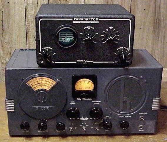
My work on the S-38Es, on the HRO-dial receiver, on the Mate for the Mighty Midget, and on various mechanical filters has caused me to think (once again) about why we ended up with 455 kHz as the IF frequency for so many radios. I’ve heard many explanations for this, but unfortunately I’ve forgotten the explanations and lost the sources. I started digging into this again today. I found the below e-mail from Al N3FRQ on the Boatanchors mailing list (2008).

I contacted Al to find out if he had learned anything else on this topic. He has not. So if anyone out there has answers to Al’s questions, or anyother info that would shed light on why they went with 455, please let us know.

——————————-

Every so often the question comes up: Why are all the IF’s 455 KHz? I’d like to get an article together that solves this riddle while the people who know are still with us. I know parts of the story, but I need help with a couple of issues. There are two major consideration is the choice of the intermediate frequency used in a superheterodyne receiver. The lower the frequency, the easier it is to attain high selectivity. Also, in the early days, before tetrode and pentode tubes, it was easier to achieve a high degree of amplification at lower frequencies. Conversely, a higher IF frequency results in better image rejection. Early superhets had the IF at 100KHz or lower in order to get adequate gain from the available triode tubes. They suffer severely from “two-spot tuning” (images). By the early 1930’s, broadcast set had settled in at 175KHz, and automobile receivers would later adopt 262KHz as a standard. The advent of the short-wave craze, and multi-band broadcast receivers dictated a higher IF frequency to achieve adequate image suppression on the short-wave bands. The broadcast band occupied 550-1500KHz at this time, and the designer encounters sever problems if his radio tunes across it’s own IF. Some shortwave sets used 1600-1700KHz for better image rejection, but one couldn’t go higher if the 160-meter ham band (1800-2000KHZ) was to be covered. Most multi-band receiver settled in near 450KHz, a comfortable distance from the first broadcast channel at 550KHz. Questions: Odd multiples of 5KHz, 455, 465, etc., were usually chosen so that the image of the carrier of a broadcast-band station could be zero-beat with the carrier of the station being tuned to achieve minimal interference. (This assumes 10KHz channel spacing. Did the Europeans (9KHz) do something else?) The Radiotron Designers Handbook, Third Edition, p. 159, states “A frequency of 455 Kc/s is receiving universal acceptance as a standard frequency, and efforts are being made to maintain this frequency free from radio interference.” (1) Do FCC and international frequency allocations reflect this? (2) I’ve heard the term “Clear-Channel IF.” Can anyone cite references? (3) At lease one news group posting claims that broadcast frequencies in a particular market are assigned to prevent strong inter-modulation products from falling near 455KHz. Is this factual? Need reference.” (4) Was this (3) at least part of the reason for “Radio Moving Day” in 1941? See: http://www.dcmemories.com/RadioMovingDay/032341WINXFreqChange.jpg (5) Many National Radio sets used a 456KHz IF’s and I think I remember a 437 somewhere. Why? Are there different considerations for short-wave CW operation? Further input, corrections, and elaborations are greatly appreciated. Scolarly reference will be looked upon with great favor. Regards, Al -- Al Klase - N3FRQ Flemington, NJ http://www.skywaves.ar88.net/ 


These Variable Capacitors Work — Ether or No Ether!

Amazing that the arguments about the presence or absence of a luminiferous ether made its way into parts advertisements in a radio magazine. This is from Radio for January 1923. (About 18 months before my dad was born.)

BTW that capacitor looks very nice, and would almost certainly still work. I have caps like that in my junk box. The shape of the blades helps address one of Pete Juliano’s complaints about analog oscillators — the inconsistent spacing of frequencies on the dial.

Thanks to the K9YA Telegram for posting this.

SolderSmoke Podcast #215 Regen Madness, KWM-4, Paesano, Mailbag

Latest N2CQR version of N0WVA’s Regen

SolderSmoke Podcast #215 is available.

25 November 2019

http://soldersmoke.com/soldersmoke215.mp3

Happy Thanksgiving!
Transit of Mercury
Book Reviews

Bill’s Minimalist Adventures:
— 15 Contacts with the ET-2
— Ethical issues: Is spotting yourself OK? OK to use TWO FETs?
— Using Reverse Beacon Network
— How to keep receiver on the right frequency
— N0WVA’s receiver sounded better, so I built a second N0WVA receiver
— Regens reach back to Edwin Howard Armstrong’s 1912-1923 breakthrough
— Regens are fun, but they are not good projects for new builders.

— Pull out those Michigan Mighty Mites and listen for yourself via on-line SDR receivers.

Pete’s Projects:
“WHEN YOU KNOW STUFF YOU CAN DO STUFF!”
— Left Coast SSB — “The Paesano” — To be featured in December 2019 SPRAT.
— Pete’s KWM-4 on The Collins Collectors Net
— Pete builds an N0WVA regen — just in time for Sweepstakes CW Saturday!
— Arduino IDE Library trouble
— uBITX 6.0? Fake News?

No more BITX40 Modules. Long Live BITX40 HOMEBREW!

BITX-101. Intriguing but on second thought, no.

MAILBAG

Steve Silverman: Lexicon: “Audible Modes.”
Felipe CU2BD Old buddy from the Azores
Michael Rainey AA1TJ: Come back Mike! The ionosphere needs you!
Jack Welch AI4SV is in 5G land (Cyprus, not the cell phone thing).
Walter AC4IM is at the San Vito Solar Observatory in Italy. DO SOMETHING WALTER!
Kostas SV3ORA has an amazing homebrew web site. Thanks Kostas!
Mike KC6SAX — How to deal with the frustration of HB projects that don’t work.
Paul KL7FLR — Pete is 7 Hz high.
Keith W3ISZ sent his photo of the Transit of Mercury.

PLEASE USE THE AMAZON SEARCH BOX ON THE SOLDERSMOKE BLOG PAGE WHEN DOING YOUR CHRISTMAS SHOPPING.

PLEASE SUBSCRIBE TO THE SOLDERSMOKE CHANNEL ON YOUTUBE.

N2CQR’s ET-2 with callsign Tattoos

The BGCD: A Regenerodyne Receiver built on Pencil, Candy, and Tea Tins. Circuit from 1937 QST

David Newkirk recently put up a nice website on ham radio. The page below provides details on the amazing creation pictured above: The BGCD: “The Byron Goodman — Clinton DeSoto Regenerodyne.” It is a beautiful piece of work, made more beautiful by the metal containers used in construction: pencil, candy and tea tins. The circuit is based on a 1937 QST article.

David’s site reminded me of the wonderful writing of his father, Rod Newkirk of “How’s DX” fame. More on him in due course.

More on the BGCD here:

http://dpnwritings.nfshost.com/ej/pictures/pictures1.htm?fbclid=IwAR2-lmJ8E1kEBT_jsB3Q8UnPaN0vc472dP783ifABK7eSxgpe5M1Pl0N77g

Building Spark-Gap Transmitters — And a Very Cool Coherer (video)

The creators of “Plasma” and “Blueprint” YouTube channels have collaborated on this very interesting video about spark-gap radio transmitters and receivers. Really nice work. Especially impressive was the coherer build by Blueprint. I detect the spirit of Nikola Tesla in his lab!

Ham Radio in Germany 1955 (video)

Don’t be deterred by the lack of English subtitles — radio amateurs around the world will be able to follow what is going on in this very interesting 1955 film. It is only about 14 minutes long.

This video takes us back to a time when hams were hams and rigs were RIGS!

Note the German OM who apparently slept fully dressed (with necktie) in order to be ready to spring into action on the ham bands in the middle of the night. That’s dedication my friends.

Also note the fellow sending out QSL cards that feature the schematic diagram of his rig. Lots of solder melted in 1955. Great stuff.

Thank God for the Heaviside Schicht!

FDIM Interview — NM0S on John Reinartz W1QP K6BJ — Scandal on an Arctic Expedition?

John Reinartz, 1QP, at the operating position of WNP aboard the Bowdoin

Bob Crane W8SX interviewed Dave Cripe NM0S about his FDIM presenation on radio pioneer John Reinartz 1QP and later K6BJ. Listen to the interview here:

http://soldersmoke.com/NM0S FDIM 2019.m4a

Here is Reinartz’s obit in the New York Times:

https://www.nytimes.com/1964/10/07/john-l-reinartz-pioneer-in-radio.html

Here is some background info on Reinartz:

http://k6bj.org/Club_History/WhoWasK6BJ.htm

Dave Cripe’s interview left me wondering what the north pole scandal was all about. I found this passage from a book that seems to partially explain what happened. Can anyone else shed more light on this unfortunate event?

DIY Waterfall — A Quick and Easy Panadaptor Using a Sig Gen and O’scope (video)

I’ve been getting waterfall envy. The panoramic frequency display is the one thing that could lure me to the dark side (SDR). Heck, they now have 3D waterfalls! What next? Holographic waterfalls? Virtual reality waterfalls? This is almost too much.

Anyway, in an effort to counteract all of this waterfall seduction and to show that us analog HDR guys can go panoramic too, I decided to try to create my own panoramic display without resort to SDR.

Of course, this is a very old technique. It was invented in the 1930s by Marcel Wallace, F3HM. He was the inventor of the Panadaptor which was the forerunner of today’s waterfall. Panoramic reception was used by the armed forces during WWII. In 1946 Hallicrafters marketed a Panadaptor for its ham radio receivers (see below).

In figuring out how to do this, I thought back to my use of my Feeltech signal generator to scan the response of a crystal filter. The Feeltech has a very handy sweep feature.

In this case I set up the Feeltech to sweep from 4.85 MHz to 4.75 MHz in one second. With the 12 MHz IF of the BITX40 module, this would result in a sweep from 7.150 to 7.250 MHz.

The sweeping Feeltech just replaced the VFO on my BITX. I hooked up the Rigol oscilloscope to the audio output of the BITX. I set the horizontal scan rate at 100 ms per cm. This would have the trace go across the whole screen in 1.2 seconds.

After a bit of fiddling, I could see signals on the 40 meter phone band. But my display would kind of drift along the screen making it hard to know the frequency of the signals I was seeing.

Alan Wolke W2AEW provided the solution. He advised me to put a big stable signal at 7.150 MHz near the input of the BITX, then use this strong signal to trigger the ‘scope scan. The HP8640B signal generator that Steve Silverman gave me (and that Dave W2DAB picked up for me in NYC) provided the triggering signal.

I put a piece of tape across the bottom of the scope display to calibrate the display. See video above.

It works! It is not as cool as the SDR waterfalls, and it does not convey nearly as much information, but it was a fun project.


Pete sent me his SBE-34

Pete is such a great guy, and such a great ham. Earlier this week I came home to find a box in the living room. In it was the SBE-34 that you see in the video. Pete had been talking about this rig about 18 months ago.

So many cool features: The main tuning dial is dual-speed. There is the “Geneva” band switching method. Hybrid, with sweep tubes in the final. All analog. A power supply that will take 110V AC or 12V DC (internal inverter). Collins mechanical filter at 455 kc. Bilateral amplifier stages. PNP Germanium transistors.

Pete suggested that I might want to use this rig for parts. No way! There is real radio history and amazing innovation in this rig. Plus, it has been worked on by Pete Juliano, N6QW.

Here is the write up from Pete’s YouTube page. Note the part about how they get the BFO signal.

Here is an example of what an IC7300 might look like some 50 years ago. It is a hybrid rig using Germanium (mostly PNP) transistors in the low level stages. So OK a couple of NPN (2N706) in several key locations such as the VFO. The driver uses a tube similar to a 12BY7 and the finals are a pair of sweep tubes, the 6GB5’s. The rig operated on four bands (mostly the then phone portions) 80, 40, 20 and 15 Meters. The power out on 80-20 was 60 Watts PEP and dropped down to 50 Watts on 15 Meters. That was a real stretch. The AGC sucked as you will see in the movie and the receiver gain was a compromise –too much on the low bands and weak on the higher. This was a bilateral design — which predates the Bitx series by some 40 years–but not the 1st.The first bilateral design was the Cosmophone – Google that one. The major selling point –a Collins mechanical filter. Also an innovation was how LSB / USB was achieved using a single crystal. It was pure magic and innovation. The basic BFO frequency of 456.38 was doubled and then doubled and tripled again. The first 2X gave you 912.76 KHz and the 2nd 2X gave you1825.52 KHz and a tripling gave you 2738.28 KHz. Mixing that back with 456.38KHz gave you 2281.9 KHz USB or LSB. The VFO operated in the 5.5 MHz range and there were heterodyne crystals to put you on the proper bands. Now that was some clever math! You can download the maintenance manual at BAMA manuals. There were some smart guys leading our ham radio efforts back in the day.

Book Review: “Man of High Fidelity: Edwin Howard Armstrong” (Free Download)

Dave W2DAB sent me this wonderful book. He picked up a copy at a recent Columbia University lecture on E. Howard Armstrong. Written by the notable science writer Lawrence Lessing, the book was first published in 1956. The paperback copy that Dave sent me came out in 1969; while 50 years old, my copy is in remarkably good shape.

I really liked the book. The author captures the technical achievements of Armstrong, while also describing vividly the world in which Armstrong lived. Being from the area, I especially liked Lessing’s description of New York City and the Hudson Valley in the early years of the 20th century. This was the world of my grandparents; Lessing’s book helped me understand it better.

For the radio amateur, I think the most gripping part of the book is the way Lessing describes the excitement of early radio. Armstrong was a true enthusiast for the new technology, and he was — even as a teenager — at the cutting edge. He was constantly striving to improve the technology, especially the receivers. Like us, he often became obsessed with his radio work, often forgoing sleep and missing family meals as he toiled away in his workshop. Lessing tells us of Armstrong’s astonishment and joy, when, upon inventing the regenerative receiver, he was suddenly able to clearly receive signals from distant stations that previously had been barely discernible. Realize that when he was doing that, he was the only person on the planet who was doing it. He was the inventor. He was the first.

Lessing gives us a lot of great information about Armstrong’s work as an officer in the U.S. Army Signal Corps in Paris during World War I. We learn more about how his desire to be able to detect noise from the electrical systems of enemy airplanes led him to the invention of our beloved superhet receivers. But my favorite Armstrong in WWI story involves his visit to the radio shack of the ship that was carrying him to the war. In the radio shack he found a conventional station. But he asked the operator if he happened to have one of the then new audion tubes. On the spot, Armstrong took the tube and rigged up a regenerative receiver. He and the ship’s radioman then delighted in hearing stations that had never before been audible. Amazing.

I was less interested in the sad tale of Armstrong’s legal patent battles, so I kind of skimmed through that. I’m also not much of an FM guy, so I’ll save those portions of the book for a later date.

I think this is an important book about a significant part of radio history. It is well written. It gets almost all of the technical details right (but sorry Mr. Lessing, radio waves are not composed of electrons). The book deserves a place on the shelf of all radio history libraries. If you can’t get a print copy, an online version can be downloaded here:

https://archive.org/details/in.ernet.dli.2015.189098

Thanks again to Dave W2DAB.

UK Wartime Radio — The Secret Listeners

We had this video on the blog before, but it was seven years ago, so it it time for a re-run.

http://www.eafa.org.uk/catalogue/5108

Thanks to Graham GW8RAK for reminding us of this.

Listening to it again, I was struck by the claim that the nationality of the operator could be discerned purely by his or her CW sending style. Is there really an Italian accent in Morse Code?


Old Station On-The-Air — A Transmitter Half as Old as Radio Itself

I’m biased, but I think it is “a thing of beauty.” With some unexpected free time available, today I followed up on my HT-37 work by cleaning and aligning the Drake 2B. I was assisted in this by one of the many great YouTube videos by Alan Wolke W2AEW.

The Drake 2B’s 50 kc and 405 kc oscillators were right were they were supposed to be — no adjustment required. And I don’t think they have been peaked since 1973. The 455 kc IF can was also very close to perfectly tuned.

Since most stations from the mid-1960s had some QSL cards on the wall behind the rig, I pulled out some old ones and put them up. Many of these contacts were made by the rigs in the picture.

If we say that 1897 marked the first use of radio, and if we assume that this HT-37 was manufactured in 1959, that means that my old transmitter has been in operation for almost HALF of the history of radio.