Phil W1PJE managed to hear and record some of the 2021 transmission (Thanks Phil). Listen here:
https://drive.google.com/file/
Phil also sent this spectrogram of the signal.
SolderSmoke Daily News — Ham Radio Blog
Serving the worldwide community of radio-electronic homebrewers. Providing blog support to the SolderSmoke podcast: http://soldersmoke.com
Phil W1PJE managed to hear and record some of the 2021 transmission (Thanks Phil). Listen here:
https://drive.google.com/file/
Phil also sent this spectrogram of the signal.
My chum, Peter/DL3PB, recently told me that Brian/WA1ZMS would broadcast a commemoration of Reginald Fessenden’s mythical (operative word) 1906 Christmas Eve AM transmission. Doesn’t that sound like fun?
“The gnawing discontent…” That is what Jean Shepherd had when he couldn’t get his Heising Modulator to work properly. We’ve all been there.
The last line in the quote from DeSoto’s book speaks to one of the major themes of this blog and of the SolderSmoke podcast: the way in which people all around the world got interested in radio in much the same way. So many of us, all around the world, often at age 13 or 14, suddenly got interested in radio. We all had (and have!) “The Knack.” This is really very nice — it is something that we have in common, something that pulls us together.
I usually try to listen in on the Old Military Radio Net on Saturday mornings (3885 kc). Lately I listen with my Mate for the Mighty Midget receiver.
This morning’s session was especially good. For me the highlight was when Masa AB9MQ called in from Normal, Illinois using his Central Electronics 20A (see below). That was one of the earliest SSB rigs. A phasing rig, it also ran AM (which was what Masa was using this morning). He had it paired up with a Central Electronics 458 VFO. You folks really need to check out Masa’s QRZ.com page:
Buzz W3EMD called in from Rhinebeck, NY. I could hear his dynamotor in the background. Buzz said hello to Masa in Japanese. FB.
Always great to hear Mike WU2D.
K9YA Telegraph ran (on Facebook) this ad from 1954. It provides an interesting view of where phone operations were in that year. Note that Dale was so intent on selling SSB gear that they were willing to make on-the-air schedules to demonstrate SSB superiority.
Dale claims that with SSB you could have TWO roundtable QSOs on the same frequency, with one group on USB and the other on LSB. I think this assumes really great opposite sideband rejection in the transmitters, and excellent selectivity in the receivers. That might have been a bit of a stretch. But the assumption here was that hams could use USB or LSB — no rigid adherence to the USB/LSB convention. And the ad seems to focus on the 75 meter band which was seen as the most important phone band at that time.
Dale was selling Collins mechanical filters for 55 dollars. That is the 1954 equivalent of $566 dollars today. No wonder the phasing method was so popular. Note that they were selling Central Electronics phasing rigs right next to the ad for the Collins filters.
I like the graph showing opposite sideband rejection with the Sideband Slicer. Note that the selected sideband was referred to as the “exalted” sideband. All Hail the Single Sideband!
Selenium rectifiers. The name kind of sounds like Dilithium crystals, possibly related to flux capacitors.
Anyway, there were two of them in the Globe Electronics V-10 VFO Deluxe that I recently bought. Obviously they had to go, so I took them out yesterday, replacing them with a 1N5408 silicon rectifier.
The new diode had a significantly lower voltage drop than the selenium rectifiers — this pushed the output voltage from the power supply up to around 200V. It is supposed to be around 185 V. So I put a 470 ohm, 5 watt resistor (found in the junkbox) in series. This brought the output voltage to 167 V. Close enough. VFO seems to be working fine.
I’m glad I did the extraction before these aging components released their nasty toxic smoke.
W3HWJ has a good article on replacing these nasty old parts, with some interesting info on their history: http://www.w3hwj.com/index_files/RBSelenium2.pdf
Backgound on the element Selenium: https://en.wikipedia.org/wiki/Selenium
Rod Newkirk, W9BRD wrote the “How’s DX?” column of QST magazine from 1947 to 1978. He had a wonderful writing style. His column was an inspiration for many of us — I write about the impact it had on me in my book SolderSmoke — Global Adventures in Wireless Electronics and here on the SolderSmoke blog.
Rod’s son David Newkirk is radio wizard himself and has produced many great articles for QST and other publications. His dad is a Silent Key and David has taken his call.
This morning I was looking at an article on David’s web site in which he looks at some of his dad’s old QSL cards. Most of the affiliations on the cards (ARRL etc.) are easily recognizable, but there was one that was unclear: WFSRA.
David figured out what it was:
————————————–
A W9BRD Affiliation Mystery Solved
My father’s pre-World-War-Two QSL cards include the usual list of affiliations: ORS (Official Relay Station), RCC (Rag Chewer’s Club), WAC (Worked All Continents), A-1 Op (A-1 Operator’s Club). One affiliation, WFSRA, remained mysterious. A clue in the correspondence column in March 1938 QST pointed me to an “I. A. R. U. News” item on page 74 of July 1935 QST, and I had my answer:
W.F.S.R.A.:
The World Friendship Society of Radio Amateurs has requested publication of the following pledge, which is the sole obligation for membership in the Society:
“I hereby promise that I will, to the best of my ability, make such use of my amateur radio station as will be conducive to international friendships; that I will never voluntarily permit by station to be used as the tool of selfish nationalistic interests; and that I will do what I can, as a radio amateur and as an individual, to promote world peace and understanding. (To be followed by the signature, address and station call.)”
Membership in the Society is open to all amateurs in all countries. All that is necessary to become a member is to copy and sign the pledge, and send it to the secretary, Duane Magill, W9DQD, 730 N. 6th St, Grand Junction, Colorado, U.S.A. Copies are preferably to be made in English or French, but may be made in the language of the member.”
———————————–
The WFSRA was apparently one of the many, many peace organizations that were born in the interwar period in response to the carnage of WWI. In addition to the QST correspondence mentioned by David, Google shows WFSRA in many articles in UK ham and SWL publications, and there is one mention of it in the May 1954 edition of Boy’s Life magazine.
Much as the CBLA seems to have been presaged by the FMLA, the IBEW seems to have much in common with the WFSRA.
— Bottom line: I still don’t know why ham radio adopted as a convention LSB below 10 MHz and USB above 10 MHz. There are several theories. but so far there is no convincing explanation in favor of any one of them. And almost all of the people involved are probably Silent Keys by now; this makes it more difficult to gather first-hand information.
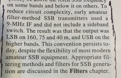
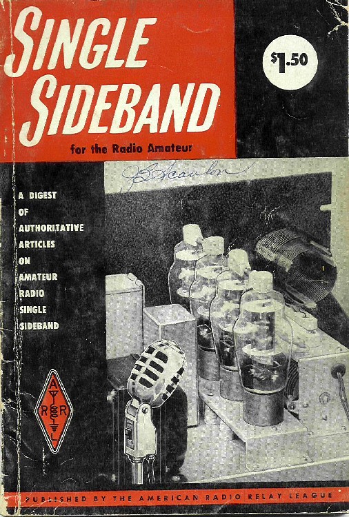
— I’m not even sure when the convention began to be observed in ham radio. Many of the early SSB books and articles make no mention of it. We don’t see it in early ARRL Handbooks. The first mention of it that I found was in the 1965 issue of the ARRL’s “Single Sideband for the Radio Amateur” page 8. This article claims that adding a provision for selectable sidebands would “add appreciably to the cost of the equipment. ” It went on to say that, “For this and other reasons there has been a species of standardization on the particular sideband used in the various amateur bands. Nearly all operations in the 3.5 and 7 Mc. phone sub-allocation is on lower sideband, while the upper sideband is used on 14, 21, and 28 Mc.”
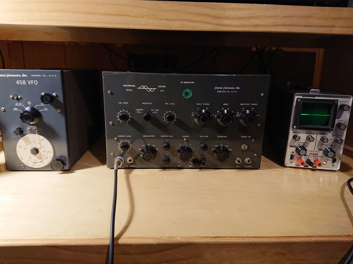
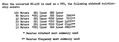
— We know that the informal convention was being followed as early as 1958. Jim N2EY reports that in 1958, the manual for the Central Electronics 20A shows that LSB was the “sideband most commonly used” on 75, with USB preferred on 20:
— There is a widely held belief that this practice originated in the design of a rig that had a 5.2 MHz VFO and a 9 MHz filter. According to this theory such a rig — due to sideband inversion — would produce LSB on 75 meters and USB on 20. But, as we have demonstrated, this doesn’t work, so this theory has to be discounted.
— Early SSB activity seems to have been concentrated on 75 meters, and there was a competition for space with AM stations. SSB operators appear to have used the very upper band edge as their gathering spot. Using LSB allowed them to operate very close to the upper band edge — a lot closer than AM stations could go. This may explain why LSB became the preferred SSB mode on 75. But how do we explain USB on 20 and above? That remains a mystery.
— It is important to remember that in the early days of SSB, for most hams there were only two important phone bands: 75 meters and 20 meters. 40 meters was CW only until 1952, and even after that was crowded with shortwave broadcast stations. So a design that allowed for both 75 and 20 was twice as good as a monoband design.
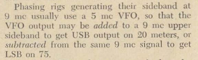
— Early on there were designs and parts for phasing rigs. You could take that ARC-5 VFO at 5 MHz, build a phasing generator around it, and then mix it with a 9 MHz to get on either band. But with just a simple switch, this kind of rig could operate on USB or LSB on either band. So the early popularity of this kid of rig does not explain the convention.
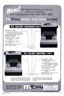
— There were a lot of surplus 5 MHz ARC-5 VFOs available. There were also FT-243 and FT-241 surplus crystals at both 5 MHz and 9 MHz that could be made into filters. Later in the 1950s, 9 MHz commercial crystal filters became available. If you used a 9 MHz filter with a 5 MHz VFO, there would be no sideband inversion in your rig. If the SSB generator was putting out LSB on 9 MHz, you’d be on LSB on both bands. So if there was a desire to have LSB on 75, why not just also have LSB on 20?
— But if you built a 5.2 MHz filter and a 9 MHz VFO, you could have LSB on 75 and USB on 20 without having to shift the carrier oscillator frequency. This would save you the trouble and expense of moving the carrier oscillator/BFO to the other side of the passband. This desire to economize and simplify may explain why we ended up with LSB on 75 and USB on 20. But this still begs the question: Why the desire for USB on 20?
— Both the manufacturers and the hams wanted there to be sideband standardization. With monoband rigs, the manufacturers would be able to cut costs by building for only one sideband. Hams also wanted to cut costs, and they did not want to have to figure out which sideband a station was on when trying to tune him in.
— By 1962-1963 Swan and Heathkit were selling mono-band SSB transceivers that used the “conventional” sidebands: The rigs for 75 and 40 meters were on LSB while the 20 meter rigs were on USB. There were no provisions for switching to the other sideband. This seems to have reinforced the practice of observing the convention. (Heath later added sideband switching to the HW monobanders — in view of the growing observation of the convention, they may have been better off sticking with their original design. Does anyone know why they did this?) But again, why USB on 20 and above?
— In 1963, Swan, by then in Oceanside California, came out with the Swan 240. Swan used a filter centered at 5174.5 kc. The VFO ran from 8953 kc to 9193 kc on 75 and 20. The VFO ran from 12222 to 12493 on 40. This gave the buyer 75 and 40 on LSB, and 20 USB with only one carrier oscillator frequency. (Swan offered a mod that allowed hams to install an additional, switchable carrier oscillator frequency. I luckily acquired one such modified rig.) But again, there is an explanation for LSB on 75, but why USB on 20 and above?
This is an important part of ham radio history. There should be a clear answer. We need to find it. If anyone has any good info on this, please let me know.
We were in Boston and the Cape Cod area this week. We stopped off at the Marconi Wireless site at Wellfleet, Mass.
This is from the National Park Service web site:
Spanning the Ocean

January 18, 1903 the first public two-way wireless communication between Europe and America occurred. With elation, communiques from President Theodore Roosevelt and King Edward VII were translated into international Morse code at the South Wellfleet and English stations, respectively, and were broadcast.
Ocean-going vessels quickly adopted Marconi apparatus to receive news broadcasts, and soon ship-to-shore transmittals were a major operation. Business and social messages could be sent for fifty cents a word. The South Wellfleet station became the lead North American facility for this function. The station’s effectiveness was limited however, so broadcasts were made between 10 pm and 2 am when atmospheric conditions were best.
This brought little enthusiasm from local residents, who endured the sounds of the crashing spark from the great three-foot rotor supplied with 30,000 watts. The sound of the spark could be heard four miles downwind from the station. Eventually, the novelty of wireless telegraphy waned. However, the need for communication at sea remained high. Effective communication resulted in numerous sea rescues, culminating in the Carpathia’s wireless-aided rescue of over 700 people from the Titanic in 1912.
For fifteen years the South Wellfleet sparkgap transmitter continued in commercial use. Skilled telegraphers sent out messages at the rate of 17 words a minute, and station CC (Cape Cod) served in effect as the first “Voice of America.”
On December 11, 2021 the American Radio Relay League, The Radio Club of America and the Antique Wireless Association will recreate these historic transmissions on 160 meters near the same location that was used in 1921, using a replica transmitter constructed by volunteers at the Antique Wireless Association. This special event is your opportunity to relive a historic moment in amateur radio history.
The operating schedule and frequency for the 1BCG Transatlantic Tests Special Event has not been established.
Additional details will be posted here when they are available.
Here is another important bit of SSB history. In May 1960, Joe Galeski W4IMP published an article in QST describing his super-simple SSB transmitter. While Tony Vitale’s “Cheap and Easy” rig was a phasing design, Joe came up with a filter rig. He built USB filter at 5775 kc. With it, he ran a VXO at around 8525 kc. This put him on 20 meter USB.
Here is the QST article: http://marc.retronik.fr/AmateurRadio/SSB/A_3_tubes_filter_rig_%28SSB%29_%5BQST_1960_5p%5D.pdf
In discussing how to put this rig on other bands, Joe got the sideband inversion question exactly right:
It kind of pains me to do this. These articles are from a long time ago, and the author is an esteemed Silent Key, but the myth about the origins of the USB/LSB convention is still out there, and as a homebrewer of SSB gear I feel obligated to point out these examples of the error that that myth is based on.
Last Friday, Pete WB9FLW and I were talking about homebrewing SSB rigs. I recommended a series of QST articles by Doug DeMaw. “Beginner’s Bench: The Principles and Building of SSB Gear” started in QST in September 1985. There were at least five parts — it continued until January 1986. (Links to the series appear below.) I hadn’t looked at these articles in years, but when I did, a big mistake jumped right out at me: In the first installment, on page 19, Doug makes the same mistake that he made in his Design Notebook:
“Now comes the conversion section of our SSB generator. We must move (heterodyne) the 9-MHz SSB signal to 3.75-4.0 MHz. Our balanced mixer works just as it does in a receiver. That is, we inject the mixer with two frequencies (9 MHz and 5 MHz) to produce a sum or a difference output frequency (9 – 5 = 4 MHz, or 9 +5 = 14 MHz) If we are to generate 75 meter SSB energy, we must chose the difference frequency. We could build an 20-meter SSB transmitter by selecting the sum of the mixer frequencies. The RF amplifiers and filter (FL2) that follow would then have to be designed for 14-MHz operation. In fact, many early two-band homemade SSB transmitters were built for for 75 and 20 meters in order to use this convenient frequency arrangement. The use of upper sideband on 20 meters and lower sideband on 75 meters may be the result of this frequency arrangement (the sidebands become inverted when switching from the difference to the sum frequency.) ”
Those last two sentences are incorrect. They repeat the “Myth,” or the “Urban Legend” about the origins of the LSB/USB convention. Contrary to what many hams now believe, with 9 MHz filter and a 5.2 MHz BFO it takes more than just switching from sum frequency to difference frequency to invert one of the sidebands.
There are two conditions needed for sideband inversion to take place:
1) You have to be taking the difference product (DeMaw got that right)
2) The unmodulated (VFO or LO) signal must be larger than the modulated signal. (DeMaw and the ARRL obviously missed that part. Repeatedly.)
This is another way of stating the simple, accurate and useful Hallas Rule: Sideband inversion only occurs when you are subtracting the signal with modulation FROM the signal without modulation.
For DeMaw’s claim to be correct, one of the SSB signals going into the balanced mixer would have to invert, and the other would have to not invert. Let’s see if that happens: He has the sideband signal being generated at 9 MHz and the VFO running around 5 MHz.
9 – 5 = 4 But we are not subtracting the modulated signal FROM the unmodulated signal. SO NO INVERSION
9 + 5 = 14 We are not subtracting at all. SO NO INVERSION.
I read these stories when they were first coming out and I really liked them. Here are all the FMLA episodes. Don’t try to read them all in one sitting. Spread them out. Savor them. Think about the message that Frank was sending us.
All of the FMLA episodes: https://tomfhome.files.wordpress.com/2019/12/frank_and_the_fmla.pdf
————————————–
Related articles, books and links:
Frank’s obit: https://www.pressdemocrat.com/article/news/frank-jones/
Frank’s book “5 Meter Telephony”: https://w5jgv.com/downloads/5-Meter%20Radiotelephony%20by%20Frank%20Jones.pdf
Frank’s 1937 Antenna Handbook: http://rfcec.com/RFCEC/Section-3%20-%20Fundamentals%20of%20RF%20Communication-Electronics/23%20-%20RADIO%20ENGINEERING%20DATA/1937%20-%20Jones%20Antenna%20Handbook%20(By%20Frank%20C.%20Jones).pdf
About the author, Michael Hopkins AB5L: https://www.rantechnology.com/index.cfm?key=view_resource&TransKey=615604E8-9DAA-40A3-9E48-4160806D893D&CategoryID=8E884CE4-9CED-4957-872B-5EBDB058D540&Small=1
Thanks to Dave Wilcox K8WPE for reminding us of all this, and for sending us the link to the FMLA archive.
It has been repeated so often and for so long that many of us have come to believe it. I myself believed it for a while. Like many myths, it has a ring of truth to it. And it is a simple, convenient explanation for a complex question:
Why do ham single sideband operators use LSB below 10 MHz, but USB above 10 MHz?
Here is the standard (but WRONG) answer:
In the early days of SSB, hams discovered that with a 9 MHz SSB generator and a VFO running around 5.2 MHz, they could easily reach both 75 meters and 20 meters (True). And because of sideband inversion, a 9 MHz LSB signal would emerge from the mixer as an LSB signal (True), while the 20 meter signal would emerge — because of sideband inversion — as a USB signal (FALSE!) That sideband inversion for the 20 meter signal explains, they claim, the LSB/USB convention we use to this day.
Why this explanation is wrong:
There is a very simple rule to determine if sideband inversion is taking place: If you are subtracting the signal with the modulation FROM the signal without the modulation (the LO or VFO) you will have sideband inversion. If not, you will NOT have sideband inversion.
So, you just have to ask yourself: For either 20 or 75 are we SUBTRACTNG the Modulated signal (9 MHz) from the unmodulated signal (5.2 MHz)?
For 75 meters we have: 9 MHz – 5.2 MHz = 3.8 MHz NO. We are not subtracting the modulated signal from the unmodulated signal. There will NOT be sideband inversion.
For 20 meters we have 9 MHz + 5.2 MHz = 14.2 MHz. NO. No subtraction here. No sideband inversion.
So it is just arithmetically impossible for there to be the kind of happy, easy, and convenient USB/LSB situation described so persistently by the myth.
———————————
We discussed this several times on the podcast and in the blog:
https://soldersmoke.blogspot.com/2015/05/sideband-inversion.html
https://soldersmoke.blogspot.com/2012/05/usblsb-urban-legend-debunked.html
This myth shows up all over the place:
We see the myth here:
http://n4trb.com/AmateurRadio/Why%20The%20Sideband%20Convention%20-%20formatted.pdf
Here the web site owner warns that this is “highly controversial.” Really? Arithmetic?
The myth is very old. Here is a clip from a 1966 issue of “73” magazine:
https://worldradiohistory.com/
Finally, to my disappointment, I found the myth being circulated by the ARRL, in the 2002 ARRL Handbook page 12.3: