
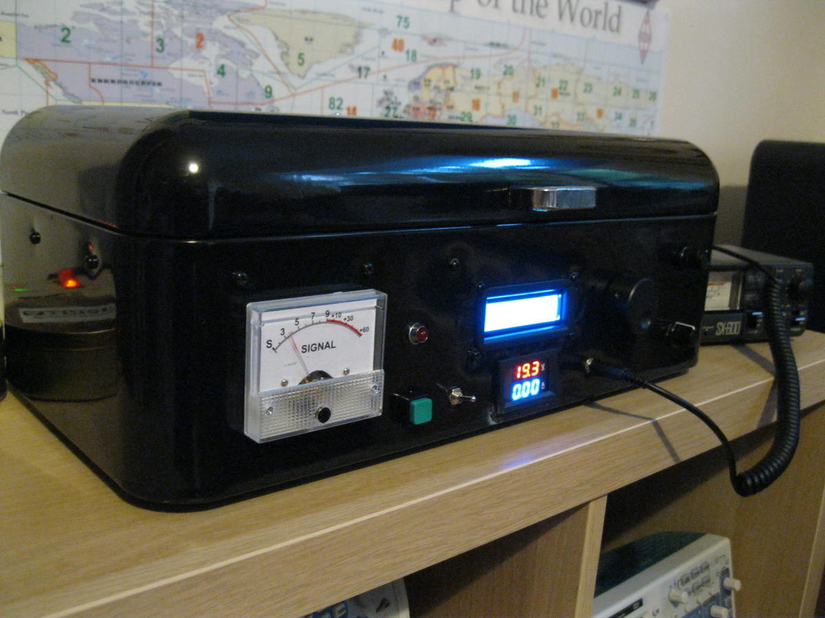
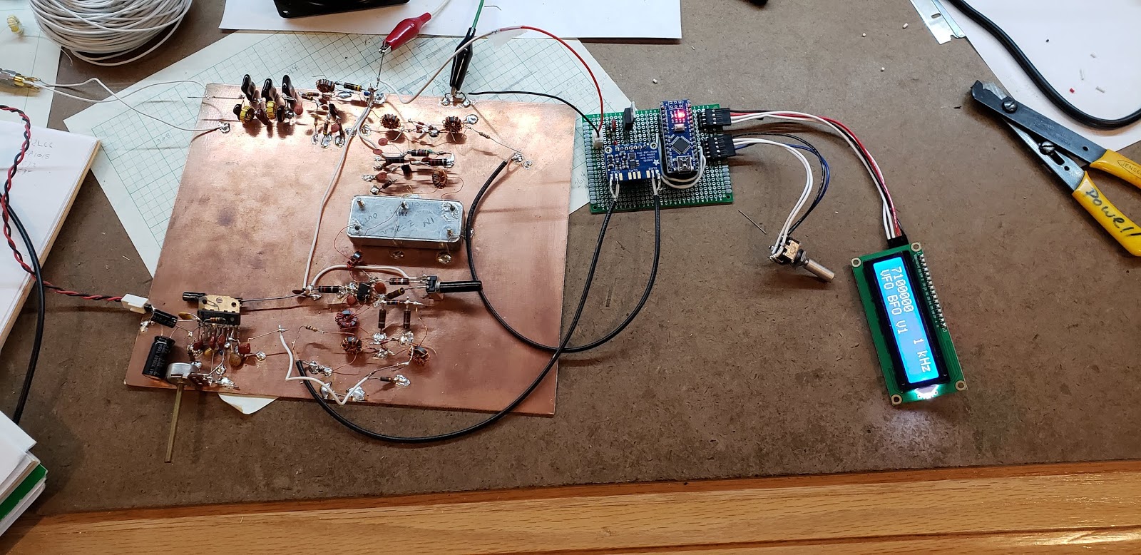
Check out that fancy frequency readout. No glowing numerals here. But it does the job.
Category: Quarantine
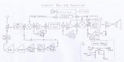
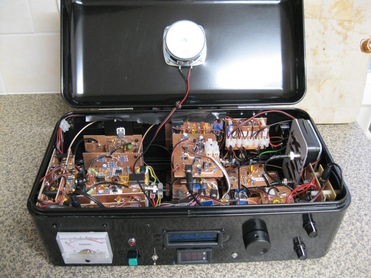
Nick M0NTV’s Quarantine Rig: The Bread Bin 80
Hi Bill,
Hope you are keeping well and staying safe.
Just thought I’d let you know about a homebrew project I’ve just completed. I call it the Bread Bin 80 – you’ll see why!
It is a single band (80m) SSB transceiver that puts out 25-30W of clean RF. It uses the familiar pairing of Arduino Uno + Si5351 (with 16×2 LCD screen and rotary encoder for tuning). Other than this though it is largely an analogue beast – which I thought you might like!
I made my own double balanced mixers which work really well. But the Si5351 can’t generate the 7 dBm of local oscillator signal to drive them so I then had to build a simple one transistor RF amp for each clock of the Si5351. I even went above and beyond the call of duty and home-brewed my own IF crystal ladder filter (although this was actually a kit).
The rig has a three stage IF cascade amplifier with 2 back to back JFETs in each stage + AGC and analogue S meter. There is something very satisfying about seeing the needle bob about as you are listening. I also put in a switchable analogue audio filter in front of the audio pre-amp which cuts out some of the higher frequency noise on the band.
Overall I’m really pleased with the rig. I’ve been working stations all over the UK and into continental Europe and getting some great reports. Except the one guy (who shall remain nameless) who wasn’t the least impressed that I was working him on a homebrew rig: he was only keen to point out that my antenna must be far too low to give me such an attenuated signal!!! I guess you can’t please everyone.
Anyway, I’ve done a bit of a write up and included some photos (outside and in) on my QRZ page if you are interested:
Thanks for sharing your home brewing story about your short wave receiver on YouTube. I’ve enjoyed following that and seeing it progress. Those little ‘Altoid’ tins are great aren’t they.
Thanks again for all your encouragement through the Soldersmoke podcast. I really enjoy it.
Stay In The Shack!

N5GTF’s FULLY INDOOR Quarantine Receiver and Antenna

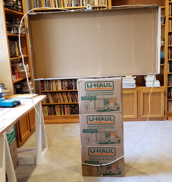
Mike N5GTF deserves special recognition for his truly remarkable SITS (Stay In The Shack) quarantine project. It is not hard to build receivers and transmitters that stay in the shack; Mike went the extra mile by keeping even his antenna inside during lockdown. Well done Mike! But that cardboard frame for the antenna seems to be crying out for some sort of inspirational slogan. Can we get a big “SITS!” in there? 73 Bill
Hi Bill,
Thought I would share a few photos of what happens when one randomly selects things from the junk box after being inspired by Pete’s recent posts about phasing SSB. It starts with a 10.7MHz crystal filter because it was large and shiny. This will prove to be somewhat inauspicious, but I’d had a pair of them for longer than I can remember… Then there were several ferrite toroids and a handful of swap meet diodes. Instant mixers, (just add enameled wire). A few 2N3904s and an MC1350P, plus a few more toroids (and wire). I’d picked up some TDA1015s awhile back. They have both a power amp and a preamp, so one of those as well. Also, an Arduino and Si5351, because Charlie Morris, ZL2CTM, has been so generous in sharing his knowledge on how to use them. Finally, about 12 feet of 14/2 w/G and a 365pF variable cap for an indoor mag loop.
Not the best reception though not bad considering the antenna’s in the basement with house wiring and metal duct work in the ceiling. The biggest issue is the IF and my choice of LO frequency. I’ve got the LO below the IF and the LO second harmonic falls inside the 40 meter band. Definitely need to fix that and move on to the transmit side.
Visits to both SolderSmoke and Pete’s blog are on my daily agenda. Thanks to you both for the frequent updates of interesting content and for providing a way to get out without going out.
Mike, N5GTF
www.mikesflightdeck.com
QSO Today — Episode 300 — Panel Discussion
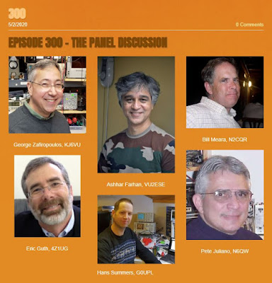
Congratulations to Eric Guth, 4Z1UG for reaching episode #300 on his QSO Today podcast. To commemorate the event, Eric organized a panel discussion. It was a real pleasure and honor to participate.
Listen to it here: https://www.qsotoday.com/podcasts/300
Thanks again Eric!
SolderSmoke Podcast #221 is available — Quarantine Rigs, Phasing, SWL, Parts Suppliers, Mailbag

 |
| Q-31. “Roll-bar” on cap. Note RGS316 coax between stages. Country markings on tuning dial |
SolderSmoke Podcast #221 is available:
25 April 2020
http://soldersmoke.com/soldersmoke221.mp3
Obviously no travelogue. QUARANTINE. SITS.
Good news: Lawyers at Dewey Cheatham and Howe report that SolderSmoke will NOT be taken off the net for brazen promotion of the S-38E receiver.
Also some good news on the FT8 vs. FT-FAKE issue. That report itself was fake.
PETE’S PROJECTS:
Phasing SSB
And what’s this about a tube CW rig?
Dean KK4DAS builds Pete’s Simple SSB rig. Quarantine Rig: The Furlough 40. See:
SHAMELESS COMMERCE DIVISION: NEW AMAZON LINK IN THE UPPER RIGHT SIDE OF SOLDERSMOKE BLOG. .
BILL’S BENCH:
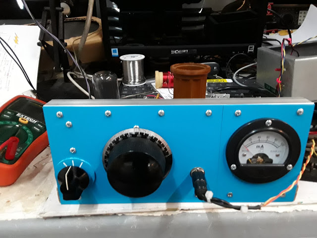
QUARANTINE PROJECT: Q-31 AM SW Receiver. April 4 through April 19. 15 days of fun. Learned a lot.
Need to pay attention to total gain. Need to measure. Not always easy. My resistor-based technique.
AM detection can be more difficult than SSB/CW detection. Germanium diodes make a big difference.
But…I don’t have to build a BFO, because these signals bring their own beat frequency.
455 CAN BE PROBLEMATIC AS AN IF – image response, making impedance matching transformers tough at those low frequencies. But WIDE filters available.
LM386 AF chip make a LOT of audio. Hard to reproduce these great results.
Great stuff you can listen to on 31 meters (9.4 –10 MHz):
n DX WaveScan
n WRMI Rock and roll
n VORW music show
n Radio Nacional De Espana (Madrid)
n China Radio International soap operas and Confucius philosophy lessons.
n China Radio International Chinese Lessons.
n Radio Greece
n Radio Republica (France)
n Radio Havana Cuba
n Radio Saudi Arabia
n WBCQ – They advised listeners to fix up an S-38 during quarantine! !!!!!!!
n WWV
SHOPPING BAG — THINGS TO GET:
— Great source for hardware (screws, nuts, bolts and more): McMaster-Carr https://www.mcmaster.com/
— Thermax RGS316 coax. Great stuff. Thanks Jim In some ways better than Belden 1671A https://soldersmoke.blogspot.com/2012/03/murphys-whiskers-shaved-with-belden.html
— Copper Clad board: Pete’s boards use CEM 1. CEM 1 is low-cost, flame-retardant, cellulose-paper-based laminate with only one layer of woven glass fabric.
NEED/WANT:
— Thermaleze magnet wire. First encountered in QRP GUYS EFHW tuner kit. Very FB
Resistor kits
NP0 cap kit
Replacement Iron for XTRonic 4000 Iron.
RIGOL PROBES Why do we burn through so many of these?
MAILBAG:
— Eric 4Z1UG Episode 300 Special
— Farhan working on ventilators. Special thanks to Dr. Gordon Gibby KX4Z.
— Jonathan-San working out of new shed in Seattle
— Grayson reminds us of the Fran Lab: https://www.youtube.com/channel/UCMLgHbpJ8qYqj3CkdbvC0Ww
— WRMI likes SolderSmoke
— Peter VK2EMU continues to build his amplifier. But it is NOT for 50 MHz. It does have 6 different meters on the front panel. But it is not a 6 meter rig!
— Rich K7SZ – “now look what you’ve done” Fixing up an S-38
— Rich WD3C Provided some great SWL links:
https://www.short-wave.info/ if you move the green dot to your location it will predict what the signal strength would be at your location and will also allow you to search by station, language, frequency, etc.
Thomas Whitherspoon, https://swling.com/blog/ Another, https://shortwaveschedule.com/ and of coarse https://www.hfunderground.com/board/index.php all the pirate broadcasters show up here.
— Paul KL7FLR amazing S-38E diagnosis from afar. Paul’s toroid tool (more to follow on this).
 |
| Pete’s Quarantine 6V6 Rig |
DX WaveScan
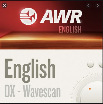
I heard this program this morning on my Q-31 receiver. It was on WRMI 9955 kHz at around 1330 UTC.
It reminded me a lot of the DX listening program of HCJB. Good stuff.
You can listen to the programs on-line at: https://awr.org/program/engmi_wav/
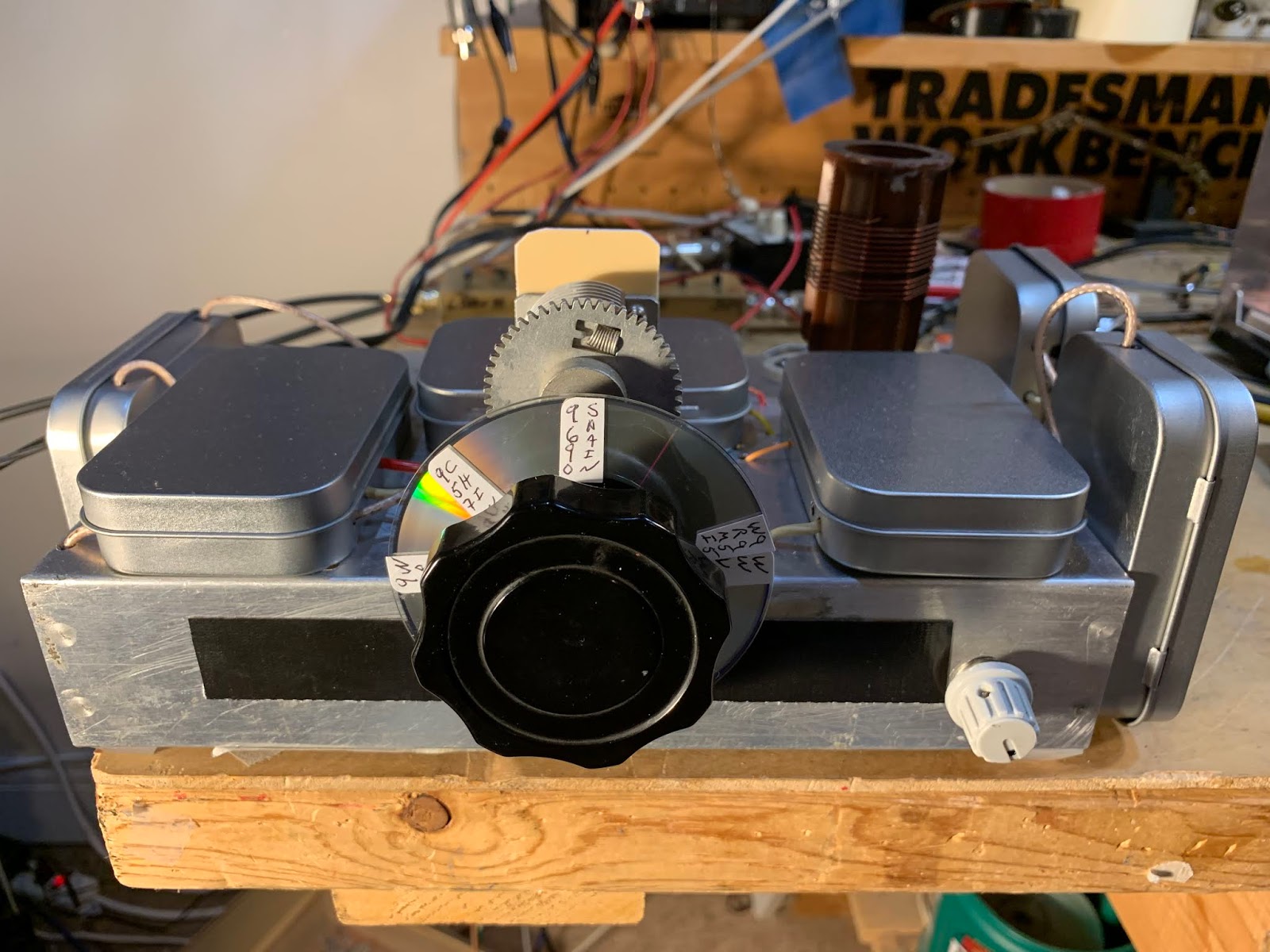
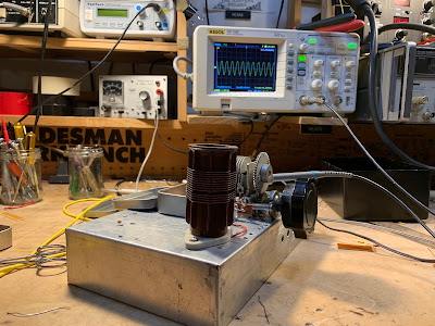
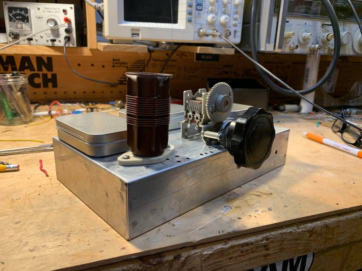
Q-31 Quarantine Receiver — All Boxed Up, Almost Done
Almost done. A few odds and ends remain, but now I have all the circuitry in their boxes.
As I was taking my walk the other day I was thinking of how I didn’t have to build a BFO for this superhet. That’s because the signals coming in on this rig bring with them their own BFO signal (the carrier).
Q-31 Quarantine Receiver — +30 db and a Germanium Diode Help a Lot (video)
Today I added two additional stages of IF amplification. This added 30 db to the receiver’s total gain. That helped a lot. I also discovered that Germanium (1N34A) diodes work a LOT better as AM detectors than do silicon diodes. This receiver is starting to sound decent. Currently listening to the VORW program on WRMI Miami.
Q-31 Quarantine Receiver — First Signals (Video)
It still needs a lot of work, but today it pulled in its first shortwave signals. See video.
Videos on the Q-31 Quarantine AM SW Receiver Project (and some pictures)
I’ve been making some short, stage-by-stage videos of my Q-31 receiver project. So far I have seven videos. They are here:
https://www.youtube.com/user/M0HBR/videos
Please subscribe to my YouTube Channel. And give me some “thumbs up” if you like the videos.
Thanks. SITS! FlattenTheCurve! 73
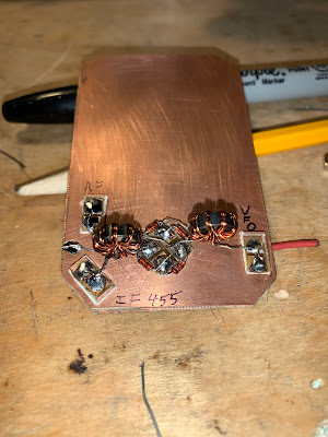 |
| Pads from Pete, toroids from Farhan |
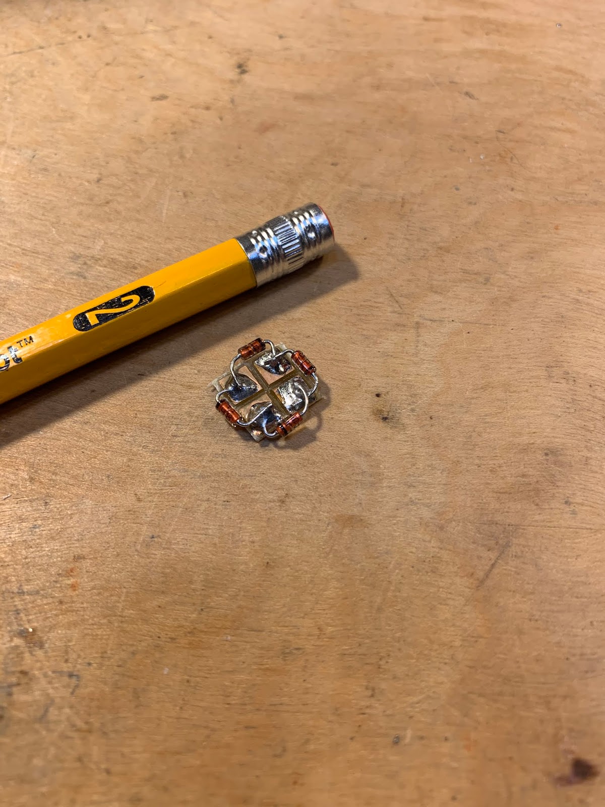 |
| The diode ring |
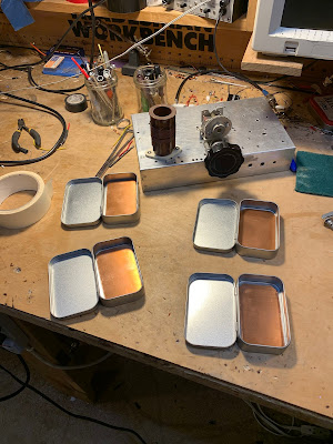 |
| Altoids-sized tins will hold the circuit boards |
 |
| Stay In The Shack — Or in the front yard. |
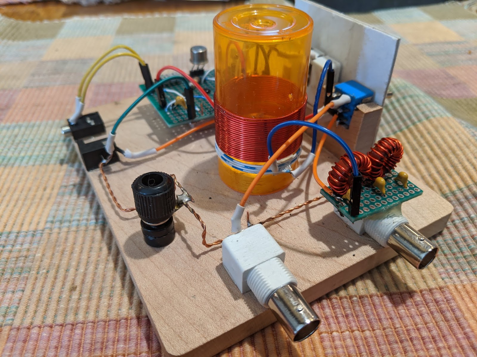
WB9IWT’s Quarantine Mighty Mite and N3FJZ’s “Hiram Percy Maxim Recognition Factor”
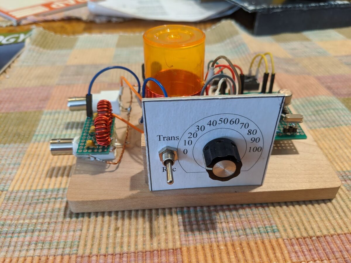

Leif WB9IWT has, during the emergency, been working on a Michigan Mighty Mite (See pictures above and below). FB Leif.
But also check out the very astute comment from Rick N3FJZ (below) . I am, of course, all in favor of the HPMR Factor. Almost all of my rigs would score quite high. Others, I know, would seek a low score. To each his own. This is all for fun.
Leif,
Great work. If a ham from the 1920’s were to see this rig, they
probably wouldn’t recognize the actual components right away (but
knowing hams, they would no doubt figure it out), but the breadboard
layout circuit flow would be immediately recognizable; e.g. the plug-in
crystal, the coil, binding post. The transistor and variable capacitor
may baffle them at first, but seeing there are three leads on the
transistor would start to give them clues.
That’s the cool part about analog discrete component radio, no matter
how many years go by, and the appearance and size of the actual
components change, the physics of what’s going on at the electron level
stays the same (SDR not withstanding).
I guess this could be a litmus test for us analog radio builders. It
could be called the “Hiram Percy Maxim Recognition Factor” or “HPMR
Factor” with a range of 0 to 1. After you build your rig, take a look
at it and pretend that you could present it to Mr. Maxim and the more he
could understand the circuits, components and circuit flow on his own,
the closer to a factor of 1 your radio would achieve. For example, an
SDR might only achieve a factor of .1 or even maybe 0, where as your rig
may achieve a factor of .8, and one of your crystal receivers would
definitely get a 1.
Someone could even workout a check list or formula where you would add
or subtract some fractional numeric values for each component you used;
e.g. you would subtract some value for every IC chip, microprocessor or
LCD display you use, and add some fractional value for each hand wound
coil, vacuum tube/valve or open air variable capacitor, et cetera.
Fun to think about.
Keep building.
Rick – N3FJZ
The Low-Cost, Open Source COVID-19 Ventilator that Farhan is Helping to Build (Video)
While many of us are just trying to pass the time by building Quarantine ham radio rigs, our good friend Farhan VU2ESE has been hard at work on a really serious project: He has been working out how to use an Arduino microcontroller as the electronic core of a simple ventilator that could save thousands of lives in the current crisis. See video above.
Here is background info on the project (from ARRL):
03/23/2020
Amateur radio volunteers from around the world have volunteered to assist University of Florida Professor Sam Lampotang and his engineering team in their quest to rapidly develop an open-source, low-cost patient ventilator that can be built anywhere from such commonly available components as PVC pipe and lawn-sprinkler valves. The amateur radio volunteers are developing Arduino-based control software that will set the respiratory rate and other key parameters in treating critically ill coronavirus victims.
Multiple volunteers responding to a call for help from Gordon Gibby, MD, KX4Z, included noted software developer Jack Purdum, W8TEE, and uBITX transceiver maker Ashhar Farhan, VU2ESE. University of Florida physicians are working to address the critical legal aspects as the design moves closer to fruition.
The ventilator’s valves would precisely time compressed oxygen flow into patient breathing circuits under Arduino control, allowing exhausted patients with “stiff” lungs impacted by viral pneumonia to survive until their body can clear the infection. The software design team is also adding simple features such as an LCD display, encoders to choose parameters, and watchdog safety features. — Thanks to Gordon Gibby, KX4Z
It is important realize that in countries around the world, many victims of COVID-19 will have no hope of getting anywhere near the kind of $50,000 ventilators found in U.S. or European hospitals. That is one of the things that makes this low cost, open-source project so important.
More details on the project here:
https://github.com/afarhan/osventproto
Please pass the word on this project. Please forward on Facebook, Re-tweet, etc.
Quarantine Project: An AM Receiver for the 31 Meter Band. The Q-31.

During this StayInTheShack (SITS) emergency, it is good to have something to work on. I decided it would be best to try to build something using only items currently in my parts collection. I’ve been getting into shortwave listening again, and I’ve discovered that the 31 meter band (9.4 – 9.9 MHz) is my favorite. Thus the “Quarantine On-Hand 31 Meter AM Receiver.” A big part of the inspiration for this project comes from the AM receiver of Paul VK3HN.
I propose that we all designate rigs built during quarantine as “Q” rigs. This will be the Q-31.
I had an old chassis on the shelf. It held my WSPR DSB rig in Rome, and various other projects over the years. It has so many holes in it that it looks like it has been used for target practice.
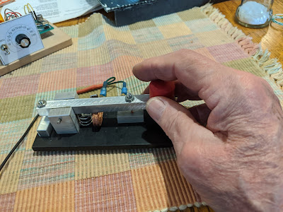
A while back Pete N6QW sent me this really magnificent variable capacitor with at least two reduction dries and an anti-backlash gear. I’ve been looking for a project that will allow me to use AND display this beautiful part. It will be the main tuning cap for the Q-39. It will stay — like the tubes in the rigs of days-gone-by — above the chassis.
While in London many years ago I picked up an old regen receiver at the Kempton Park rally. The parts are still in my junk box. A very nice 1.7 uH plug in coil (with socket) was there. That will be the main coil in the Hartley Oscillator that will be the VFO. I will add a few turns for the feedback coil (see circuit diagram below). I wonder of that Eddystone coil was around for the Blitz?
On the recommendation of our old friend Rogier (originally PA1ZZ), a few years ago Elisa got me a set of grey Altoids-sized metal boxes. I will have three of these atop the target-practice chassis (they will provide shielding and will cover up the holes):
— One will hold the bandpass filter (designed with the Elsie program) and the mixer (probably diode ring, with transformers from Farhan).
— One will hold two IF amps with a 10 kHz 455 kHz IF filter between them (thanks to Bruce KK0S for the filters).
— One will hold the AM detector and the AF amplifiers.
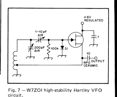
— A fourth box will be under the chassis and will hold all the powered parts of the VFO circuitry. I base my VFOs on this simple circuit from page 34 of Solid State Design for the Radio Amateur:
This quarantine looks like it is going to last a long time, so it is best to take your time on projects like this. I might work on the VFO today. No need to rush…
I am shooting videos as I go along and will at some point start putting them up on my YouTube channel.
So, I suggest that any of you who are feeling bored and confined (that would be almost all of us) fight back by launching a Quarantine “Q-Rig” project. Send reports to me — I will try to put them on the SolderSmoke blog.
Remember: StayInThe Shack! #SITS! #flattenthecurve.
73 Bill